

Page 1
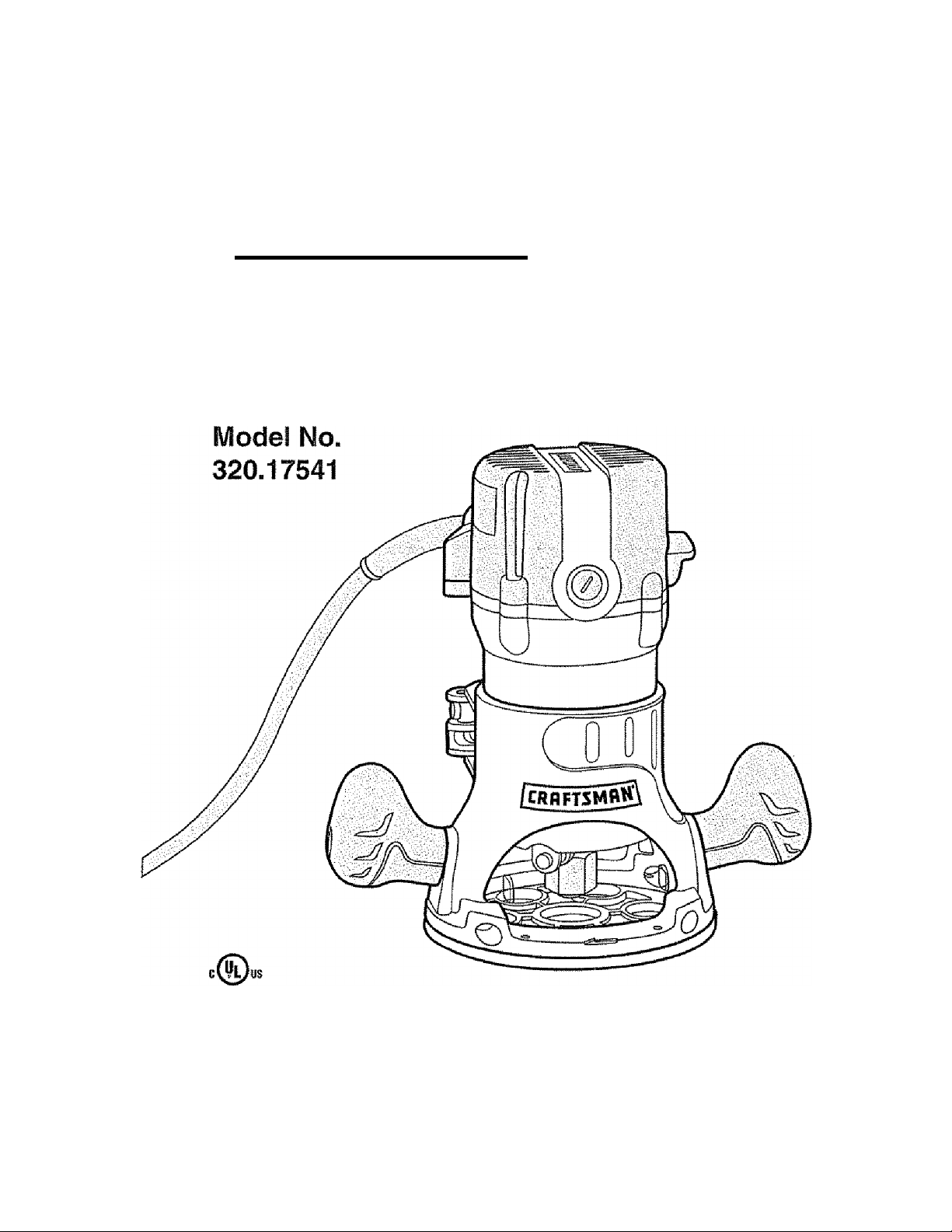
Operator's Manual
CRHFTSMHN
9.5 Amp 13/4 Peak HP
Fixed Base Router
DOUBLE INSULATID
A CAUTION Read, understand and foliow
all Safety Rules and Operating Instructions
in this Manual before using this product.
Sears, Roebuck and Co.,
Hoffman Estates, IL 60179 U.S.A.
Visit our Craftsman website: www.craftsman.com
•WARRANTY
» SAFETY
• UNPACKING
• DESCRIPTION
• ASSFiUfBUY
• OPERATION
• ADJUSTMENTS
• MAINTENANCE
Page 2

Warranty..
Safety Symbols.......................
Safety Instructions...,..,...,—........
Unpacking
Description
Assembly........................
Operation ..................................
Maintenance
Accessories
Repair Parts.
Sears Repair Parts Phone Numbers,
...................................
.........................................
....................................
.........
.......
................................
.....
.................................
.
..........
.
.
.
.
...Page 2
...Page 3
...Pages 4-10
...Pages 10-11
.. Pages 11 -14
Pages 14 -17
...Pages 18-29
...Pages 30-31
...Pages 32-33
...Pages 34-37
... Back Cover
ONE YEAR FULL WARRANTY ON CRAFTSMAN® PRODUCT
Ilf this Craftsman product fails due to a defect in material or workmanship within one year
from the date of purchase, RETURN IT TO THE NEAREST SEARS STORE OR PARTS
AMD repair CENTER OR OTHER CRAFTSMAN OUTLET IN THE UNITED STATES
FOR FREE REPLACEMENT.
This warranty does not include expendable parts such as tamps, batteries, bits or blades.
If this Craftsman product is used for commerciaf or rental purposes, this warranty applies
for only 90 days from the date of purchase.
This warranty gives you specific legal rights, and you may also have other rights, which vary
from state to state.
Sears, Roebuck and Co., Hoffman Estates, IL 60179
SAVE THESE INSTRUCTIONS! READ ALL INSTRUCTIONS!
Page 3

SAFETY SYMBOLS
The purpose of safety symbols is to attract your attention to possible dangers.
The safety symbols, and the explanations with them, deserve your careful
attention and understanding. The symbol warnings DO NOT by themselves
eliminate any danger. The instructions and warnings they give are no substitutes
for proper accident prevention measures.
/t\ WARNING: BE SURE to read and understand all safety instructions in
this manual, including all safety alert symbols such as “DANGER”, “WARNING”
and “CAUTION”, BEFORE using this router. Failure to follow all instructions
fisted below may result in electric shock, fire and/or serious personal injury.
SYMBOL MEANING
SAFETY ALERT SYMBOL: Indicates DANGER, WARNING, OR
CAUTION. May be used in conjunction with other symbols or pictographs.
Failure to obey this safety warning WILL result in death or
serious injury to yourself or to others. Always follow the
safety precautions to reduce the risk of fire, electric shock
and personal injury.
Failure to obey this safety warning CAN result In death or
Awarning
A CAUTION
DAMAGE PREVENTION AND INFORMATION MESSAGES
These inform user of important Information and/or instructions that could lead to
equipment or other property damage if not followed. Each message is preceded by the
word “NOTE:" as in the example below:
NOTE: Equipment and/or property damage may result if these instructions
are not followed.
serious injury to yourself or to others. Always follow the
safety precautions to reduce the risk of fire, electric shock
and personal injury.
Failure to obey this safety warning MAY result in personal
injury to yourself or others or property damage. Always
follow the safety precautions to reduce the risk of fire,
electric shock and personal injury.
AWARNING: The operation of any router can result in
foreign objects being thrown into your eyes, which can
result in severe eye damage. Before beginning power
tool operation, ALWAYS wear safety goggles or safety
glasses with side shield and a full-face shield when
needed. We recommend a Wide Vision Safety Mask for
use over eyeglasses or standard safety glasses with
side shield, available at Sears Stores or other Craftsman
Outlets.
w -m Jr Jr
Page 4

SAFETY INSTRUCTIONS
A WARNING: BE sure to read and understand all Instructions in this
manual before using this router. Failure to follow all instructions may result
electric shock, fire and/or serious personal injury.
WORK AREA SAFETY
1 Keep your work area clean and well lit. Cluttered workbenches and dark areas
invite accidents.
2. DO NOT operate power tools in explosive atmospheres, such as in the presence
of flammable liquids, gases, or dust Power tools create sparks which may ignite
the dust or fumes.
3 Keep bystanders, children and visitors away while operating a power tool.
Distractions can cause you to iose control.
4. Make your workshop childproof with padlocks and master switches. Lock tools
away when not in use.
5 MAKE SURE the work area has ample lighting so you can see the work and that
there are no obstructions that will interfere with safe operation BEFORE using
your router.
PERSONAL SAFETY
1: KNOW your power tool. Read this operator's manual carefully, Learn the router's
applications and limitations, as well as the specific potential hazards related to this
tooi,
2. STAY ALERT, watch what you are doing and use common sense when operating
a power tool
3. DO NOT use tool while tired or under the influence of drugs, alcohol or medication.
A moment of inattention while operating power tools may result in serious persona!
injury.
4. DRESS properly. DO NOT wear loose clothing or jewelry. Puil back long hair. Keep
your hair, clothing, and gloves away from moving parts. Loose clothing, or long hair
can be caught in moving parts. Air vents often cover moving parts and should also
be avoided.
5. AVOID accidental starting. Be sure switch is in “OFF” position before plugging in.
DO NOT carry tools with your finger on the switch. Carrying tools with your finger
on the switch or plugging in tools that have the switch in the “ON" position invites
accidents-
6. REMOVE adjusting keys or blade wrenches before turning the tool “ON". A wrench
that is left attached to a rotating part of the tool may result in personal injury.
7. Do not overreach. Keep proper footing and balance at all times. Proper footing
and balance enables better control of the tool in unexpected situations,
ALWAYS SECURE YOUR WORK. Use clamps or a vise to hold workpiece securely.
8.
It is safer than using your hand and frees both hands to operate tool.
USE SAFETY EQUIPMENT. Always wear eye protection. Dust mask, non-skid safety
shoes, hard hat, or hearing protection must be used for appropriate conditions.
DO NOT USE ON A LADDER or unstable support Stable footing on a solid surface
10.
enables better control of the tool in unexpected situations.
Page 5

SAFETY INSTRUCTIONS coni.
TOOL USE AND CARE SAFETY
A WARNING: BE SURE to read and understand all instructions before
operating this router. Failure to follow all instructions listed below may result
in electric shock, fire and/or serious personal injury.
1. ALWAYS use clamps or other practical ways to secure and support the workpiece
to a stable platform. Holding the work by hand or against your body is unstable and
may lead to loss of control.
DO NOT force the tool. Use the correct tool and bit for your application. The correct
2.
too! and bit will do the job better and safer at the rate for which it is designed.
DO NOT use the tool if switch does not turn it “On” or “Off”. Any tool that cannot be
controlled with the switch is dangerous and must be repaired.
DISCONNECT the plug from the power source before making any adjustments,
changing accessories or storing the tool. Such preventive safety measures reduce
the risk of starting the tool accidentally-
NEVER leave the tool running. ALWAYS turn it off. DO NOT leave the tool until it
comes to a complete stop,
STORE Idle tools out of the reach of children and other untrained persons. Tools
are dangerous in the hands of untrained users.
MAINTAIN tools with care. Keep cutting tools sharp and clean. Properly maintained
tools with sharp cutting edges are less likely to bind and are easier to control.
CHECK for misalignment or binding of moving parts, breakage of parts, and any
other condition that may affect the tool's operation. If damaged, have the tool serviced
before using. Many accidents are caused by poorly maintained tools.
USE ONLY accessories that are recommended for this tool. Accessories that may be
suitable for one tool may become hazardous when used on another tool.
ELECTRICAL SAFETY
A WARNING: Do not permit fingers to touch the terminals of plug when
instaliing or removing the plug from the outlet.
1 Doubie insulated tools are equipped with a polarized plug (one blade is wider
than the other).This plug will fit in a polarized outlet only one way. If the plug
does not fit fully in the outlet, reverse the plug. If it still does not fit, contact a qualified
electrician to install a polarized outlet Do not change the plug in any way.
2. Doubie insulation B eliminates the need for the three-wire grounded power
cord and grounded power supply system. Applicable only to Class !l (double-insulated)
tools. This router motor is double insulated.
^ WARNING: Double insulation DOES NOT take the place of normal safety
precautions when operating this tool.
Page 6

SAFETY INSTRUCTIONS cont.
ELECTRICAL SAFETY cont.
3. BEFORE plugging in the tool, BE SURE that the outlet voltage supplied is within the
voltage marked on the tool's data plate, DO NOT use “AC only" rated tools with a DC
power supply.
4. AVOID body contact with grounded surfaces, such as pipes, radiators, ranges and
refrigerators. There is an increased risk of electric shock if your body is grounded.
5. DO NOT expose power tools to rain or wet conditions or use power tools in wet
or damp locations. Water entering a power tool will increase the risk of eiectric shock.
6 inspect tool cords for damage. Have damaged tool cords repaired at a Sear
Service Center. BE SURE to slay constantiy aware of the cord location and keep
it we!i away from the moving router.
7. DO NOT abuse the cord. NEVER use the cord to carry the tool by or to pull the
plug from the outlet Keep cord away from heat, oil, sharp edges or moving parts.
Replace damaged cords immediately. Damaged cords increase the risk of electric shock,
EXTENSION CORDS
Use a proper extension cord. ONLY use cords listed by Undenvriters Laboratories (UL).
Other extension cords can cause a drop in line voltage, resulting in a loss of power and
overheating of tool. For this tool an AWG (American Wire Gauge) size of at least 14-gauge
is recommended for an extension cord of 25-ft. or less in length. Use 12-gauge for an
extension cord of 50-ft,
Remember, a smaller wire gauge size has greater capacity than a larger number
(14-gauge wire has more capacity than 16-gauge wire; 12-gauge wire has more capacity
than 14-gauge), When in doubt use the smaller number. When operating a power tool
outdoors, use an outdoor extension cord marked “W-A” or “W”. These cords are rated
for outdoor use and reduce the risk of electric shock.
Extension cords 100-tt. or longer are not recommended.
AcAUTION: Keep the extension cord clear of the working area. Position the
cord so that it will not get caught on lumber, tools or other obstructions while you
are working with a power tool.
AwARNING: Check extension cords before each use. If damaged replace
Immediately. Never use tool with a damaged cord since touching the damaged area
could cause electrical shock, resulting in serious injury.
SAFETY SYMBOLS FOR YOUR TOOL
The label on your tool may include the following symbols.
V. .....
........................................................Volts
A....
..........................................................
Hz..
..................................-.......................
W. .
..........................................................
min..„
.......................................
.................................................
................................................„„....Direct current
no
...........................................................
B
.......................................................
.../min
........................................Revolutions or Strokes per minute
/fy......
....................................................
...............
Amps
Hertz
Watts
.Minutes
.„.„..Alternating current
.No-load speed
.....Class li construction, Double insulated
Indicates danger, warning or caution.
It means attention! Your safety is involved.
Page 7

SAFETY INSTRUCTIONS cont.
iSIEFliN^I Cwf IEf
1. tf any part of this router is missing or should break, bend, or fail In any way;
or should any electrical component fall to perform properly: SHUT OFF
the power switch and remove the router plug from the power source and have the
missing, damaged or faiied parts repiaced BEFORE resuming operation,
2. Tool service must be performed only at a Sears Parts and Repair Center.
Service or maintenance performed by unqualified personnel could resuit in a
risk of injury,
3. When servicing a tool, use only identical replacement parts. Follow instructions
in the maintenance section of this manual. Use of unauthorized parts or failure to
follow maintenance instructions may create a risk of electric shock or Injury.
SAFETY RULES FOR ROUTERS
A CAUTION: Cutter bits coast after router is switched off.
1. HOLD TOOL by insulated gripping surfaces (handles) when performing an
operation where the cutting tool may contact hidden wiring or its own cord.
Contact with a "live” wire wili make the exposed metal parts of the tool “live" and
shock the operator,
2. Maintain a firm grip on the router with both hands to resist starting torque.
3. NEVER attempt to use the router motor without first installing It in an approved
fixed base. Failure to heed this warning could result in personal injury and
damage to the motor.
4,
MAKE SURE the motor housing does not move up or down when damped in the
fixed base. If motor is not securely clamped in base, adfustments will
not be accurate.
DO NOT HAND-HOLD THE ROUTER IN AN UPSIDE DOWN OR HORIZONTAL
5.
POSITION. The motor can separate from the base if not properly attached according
to the instructions,
6. TIGHTEN COLLET / NUT securely to prevent the cutter bit from slipping. If the
collet/nut is not securely tightened, the cutter bit may detach during use, causing serious
personal injury.
7. NEVER tighten coliet/nut without a cutter bit installed in the collet/nut.
8. USE CLAMPS or other practicai ways to secure and support the workpiece to
a stable platform and hold the workpiece rigidly in position. Holding the work by
hand or against your body is unstable and may lead to loss of control,
9. NEVER hold the piece being cut in your hands or across your legs. It is important
to support and clamp the workpiece properly in order to minimize body exposure,
bit binding, or loss of control.
10. ALWAYS keep chip shield clean and in place.
11. STAY ALERT and clear the Router cutter bit path of any obstructions BEFORE
starting the motor. Keep cutting area clear of all foreign objects while motor is
running.
12. CHECK TO SEE that the cord will not “hang up” during routing operation.
Page 8

SAFETY INSTRUCTIONS cont.
SAFETY RULES FOR ROUTERS cont
MAKE SURE the cutter bit is not in contact with the workpiece before the switch
13
is turned on. The fait must ALWAYS be running at full speed before contacting
the workpiece.
14. KEEP HANDS CLEAR OF CUTTER BIT when motor is running to prevent
personal Injury.
15. provide CLEARANCE under workpiece for router cutter bit when through-cutting.
16. KEEP CUTTING PRESSURE CONSTANT. Do not overbad the motor,
17. USE ONLY sharp cutter bits that are not chipped or cracked. Blunt cutter bits
will cause stalling and burn the workpiece.
NEVER use this router motor with a cutter bit larger than 3V2-inch in diameter.
18
ALWAYS USE cutter bits that are designed for this router. Never use cutter bits
19
which are larger in diameter than the opening in the router sub-base . Cutter bits
that have cutter diameters larger than the opening could cause possible loss of control
or create other hazardous condition that could cause serious personal injury.
The subbase on this fixed base router has an opening of 1 V4-lnch. To use cutter
20
bits with a larger diameter, install and use a subbase with a larger diameter opening
(sold separately) at Sears stores or other Craftsman outlets.
DO NOT use large router cutter bits for freehand routing. Use of large cutter bits
21.
when freehand routing could cause loss of control or create hazardous conditions that
couid result in serious personal injury. If using a router table, large bits
should be used for edging only.
BE SURE CUTTER BIT is centered In template guide (sold separately) prior to
22.
template guide applications to avoid personal injury or damage to finished work.
DO NOT REMOVE more than Vs-inch in a single pass. Excessive depth of cut can
23
result in loss of control that could result in personal injury.
24. After completing a cut, turn motor OFF and let it come to a complete stop
BEFORE REMOVING router from workpiece.
Let the motor come to a COMPLETE STOP before putting the router down. Cutter
25.
bits coast after power is turned off.
ONLY use router tables that conform to safe woodworking practices and offer
26
proper guarding for the cutter bit. Use router tables that are UL classified and identified
suitable for use with this specific router model. Failure to comply could result in
serious personal injury.
Only use router tables with on-board switch controlled receptacles. Failure to use
27
router tables with all the appropriate safety features could result in serious personal injury.
DISCONNECTTHETOOL FROM POWER SOURCE before making any adjustments
28
or changing cutter bits.
29. If you are changing a bit immediately after use, BE CAREFUL NOT TO TOUCH
the collet/nut or cutter bit with your hands or fingers.The heat buildup from
cutting could cause severe burns. ALWAYS use the wrench provided.
AVOID ‘‘CLIMB CUTTING”. See “OPERATION” (pages 26 and 27) section
30.
in this manual. “Climb-cutting” increases the chance for loss of control resulting in
possible serious injury.
Page 9

SAFETY INSTRUCTIONS cont
A. WARNING: Use of this tool ean generate dust containing chemicals
known to cause cancer, birth defects or other reproductive harm.
Some examples of these chemicals are:
• Lead from lead-based paints.
• Crystalline silica from bricks and cement and other masonry products..
• Arsenic and chromium, from chemically treated lumber.
Your risk from these exposures varies, depending upon how often you
do this type of work.To reduce your exposure to these chemicals:
• Work In a well-ventilated area.
»Work with approved safety equipment, such as those dust masks
that are specially designed to filter out microscopic particles.
Avoid prolonged contact with dust from power sanding, sawing, grinding,
drilling and other construction activities. Wear protective clothing and wash
exposed areas with soap and water. Allowing dust to get into your mouth,
eyes, or lay on the skin may promote absorption of harmful chemicals.
WARNING: Use of this tool can generate and/or disburse dust, which
may cause serious and permanent respiratory or other injury. Always use
NIOSH/OSHA approved respiratory protection appropriate for the dust exposure.
Direct particles away from face and body.
ADDITIONAL RULES FOR SAFE OPERATION
¿ii WARNING: BE SURE to read and understand ail instructions. Failure to
follow all instructions listed below may result in electric shock, fire and/or
serious personal injury.
Know your power tool. Read this operator’s manual carefully. Learn the applications
and limitations, as well as the specific potential hazards related to this tool. Following
this rule will reduce the risk of electric shock, fire or serious injury.
ALWAYS wear safety glasses or eye shields when using this router. Everyday
eyeglasses have only impact-resistant lenses; they are NOT safety glasses.
PROTECT your lungs. Wear a face mask or dust mask if the operation is dusty.
3.
4.
PROTECT your hearing. Wear appropriate personal hearing protection during use.
Under some conditions noise from this product may contribute to hearing loss.
all VISTORS AND gySTANDERS MUST wear the same safety equipment that the
operator of the router wears.
INSPECT the tool cords periodically and if damaged have them repaired at your
nearest Sears Service Center. BE AWARE of the cord location.
Page 10

SAFETY INSTRUCTIONS cont.
ADDITIONAL RULES FOR SAFE OPERATION coni
7, ALWAYS check the tool for damaged parts. Before further use of the tool, a guard or
other part that is damaged should be carefully checked to determine if it will operate
properly and perform its intended function. Check for misalignment or binding of
moving parts, breakage of parts, and any other condition that may affect the tool's
operation. A guard or other part that is damaged should be properly repaired or replaced
at a Sears Service Center.
8 remove all nails from lumber before routing.
9. SAVE THESE INSTRUCTIONS. Refer to them frequently and use them to Instruct
others who may use this tool. If someone borrows this tool, make sure they have
these instructions also.
UNPACKING
/K WARNING: Your router should NEVER be connected to the power source
when you are assembling parts, making adjustments, installing or removing
collets / nuts, cutter bits, cleaning or when it is not In use. Disconnecting the
router will prevent accidental starting, which could cause serious personal
injury.
_____________________ ___
When unpacking the box don’t discard any packing materiais until all of the contents are
accounted for:
1. Carefully lift the Router Motor and Fixed Base with the 1/2-in. collet/nut already
installed, out of the carton and place on a stable flat surface.
2. Open the parts bag to locate the following:
«Sawdust Extraction Hood and 2 Screws used to attach hood to base
• 1/4-in. Collet/Nut
• Collet/Nut wrench
3. Inspect the items carefully to make sure that no breakage or damage has occurred
during shipping. If any of the items mentioned are missing, (refer to “PARTS LIST’
illustration on page 11), return the router to your nearest Sears store or Craftsman
outlet to have the router replaced.
/K WARNING: If any parts are broken or missing, DO NOT attempt to plug
in the power cord or operate router until the broken or missing parts are
replaced. Failure to do so could result in possible serious injury.
10
Page 11
UNPACKING cont.
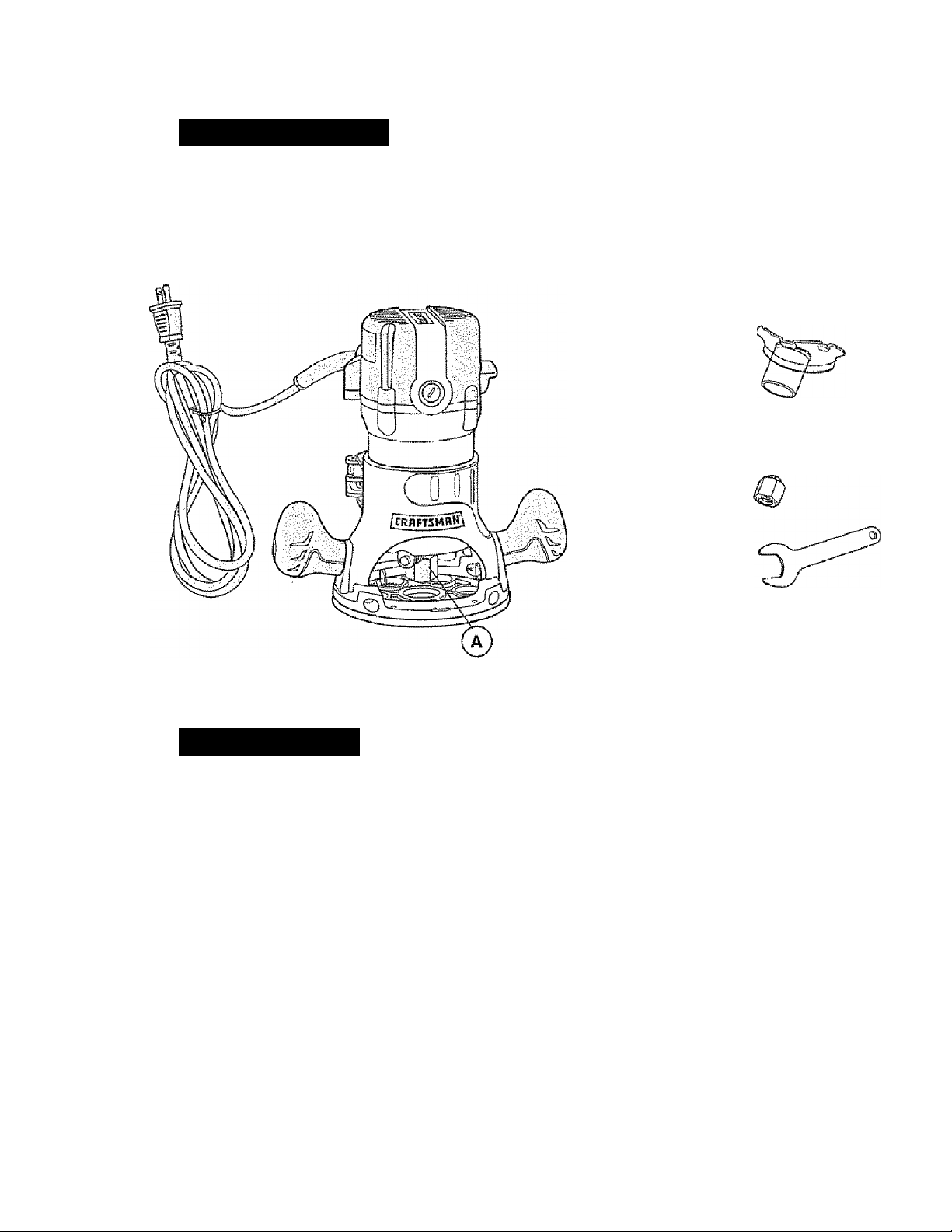
PARTS LIST (Fig.1)
1. Fixed Base and Motor wish Va-in Coiies/Nut ®
2. Sawdust
Extraction Hood
3. 2 Screws
{for attaching Hood)
4. 1/4-in. Collet/Nut
5. Coliet/Nut Wrench
DESCRIPTION
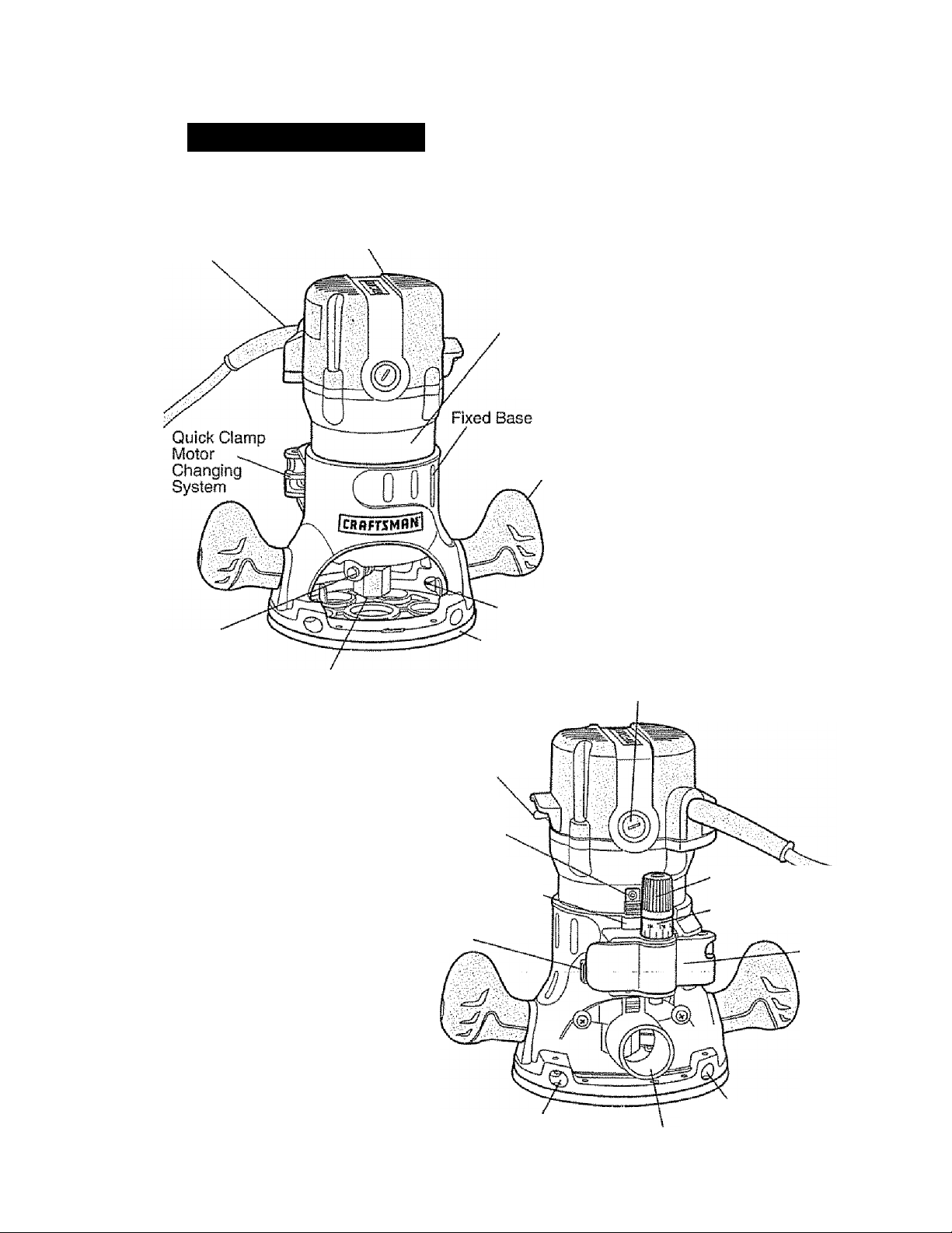
KNOW YOUR FIXED BASE ROUTER (Fig. 2)
NOTE: Before attempting to use your router, famiiiarize yourself with all of the operating features and safety requirements.
Your fixed base router has a precision-buiit electric motor and it should only be connected
to a 120-volt, 60-Hz AC ONLY power supply (normal household current). DO NOT operate
on direct current (DC). This large voltage drop will cause a loss of power and the motor
will overheat, if the router does notiiperate when piugged inio a correct 120-volt,
60-Hz AC ONLY outlet, check the power supply. This router has an 8-ft., 2-wire power
cord (no adapter needed).
11
Page 12

DESCRIPTION coni.
KNOW YOUR FIXED BASE ROUTER cont. (Fig. 2)
This Fixed Base Router has the following features:
1. Powerful, 9.5 Amp Soft Start Motor develops 1 % Peak HP to handle most
routing |obs
2. Single speed 25,000 RPM {no-load speed) helps provide a quality finish
in most materials
3. Fixed Base features Coarse and Fine Depth Adjustments for accurate set-ups.
Ideal for use with router table, sold separately.
4. Spindle Lock for easy 1-wrench bit changes, includes 1/4-in. and 1/2-in.
Self-Releasing Collets/Nuts for use with a wide variety of 1/4-in. and 1/2-in, router
bits, sold separately.
5. 100% Ball Bearings for smooth, efficient operation and long life.
6. Base features Ergonomically Designed Handles for comfort,
maximum control.
7. Base features Large Base Opening and Large Chip Shield, combined with 3 LED
Worklights on Motor to provide the highest visibility of bit and workpiece.
8. Durable Non-marring Sub-base glides smoothly over workpiece. Sub-base has
cutter-bit opening of 1 V4-inches. Do Not Use a bit with a cutter diameter larger than
1 V4-in, as it wiil not pass through the sub-base openingl
9 gagg constructed of Die-Cast Aluminum to provide durability and stability.
10. Motor Housing constructed of High Density Nylon and Precision Milled Cast
Aluminum for strength and exact fit into base.
11. High-impact resistant Motor Housing Top Cap and Handles on Base help
protect tool from damage.
12. Conveniently located On/OffToggle Switch, side mounted for added visibility,
©aSy elUCBoo^
13. Sawdust Extraction Hood allows base to hook up to 1 V4-inch vac hose attachment,
sold separately.
14. “LIVE TOOL INDICATOR” Light is green when saw is plugged into a power
source. Light is located on motor housing top cap next to power cord inlet.
15. Replaceable Brushes (sold separately) for dependable service.
12
Page 13
DESCRIPTION coni
KNOW YOUR FIXED BASE ROUTER cont. (Fig. 2)
“Live Tool
indicator’' Light
Spindfe Lock
Self-Releasing Coilets/Nuts
System 1/4 and 1/2-inch
Collets/Nuts
(1/2-in. installed at factory)
Motor Housing
Top Cap
Motor Housing
Precision
Milled Cast
Aiuminum
for Exact Fit
Handles
Clear Plastic
Chip Shield
Non-Marring
Sub-Base
On/Olf
Toggle
Switch
Replaceable Brushes
{sold separately)
Motor
Housing
Keystrip
Base Keystrip-Siot
(Engages Motor
Housing Keystrip)
Coarse
Adjustment
Knob
Edge Guide
Mounting Slot
13
Sawdust
Extraction
Hood
Micro
Adjustment Dial
■with Depth Indicator Ring
Quick
CJanip,, Motor
Changing
System
Edge Guide
Mounting Slot
Page 14

DESCRIPTION cont.
PRODUCT SPECIFICATIONS "
Rating
No-load Speed
Peak HP
Input
Collets/Nuts and Cutter Sit Shank Diameters
Fixed Base Diameter
Sub Base Opening (Diameter for cutter bit use)
Sub Base Thickness
Fixed Base Depth of Cut
9,5 Amps
25,000 RPM
13/4
120-volts, 60Hz AC
1/4-in. 1/2-in.
6-inches
1 V4-inches
0.23-inches (6mm)
13/4-inches (45mm)
ASSEMBLY
NOTE: This tool is shipped completely assembled.To install or remove bits
or add accessories such as sawdust ejection hoods for hook-up to vacs, see
the following instructions.
SELECTING THE CUTTER BIT
This router comes with 1/4-in, and 1/2-in. coiiets/nuts that accept 1/4 and 1/2-inch
diameter shanked cutter bits.
A WARNING: Do not use router cutter bits that have a cutler bit diameter
larger than 1 V4-inches as they will not fit through the sub-base opening, and
wlli cause damage to the sub-base, the motor, and could cause serious personal
injury to the operator.
NOTE: The sub-base installed on this router has an opening of lV4-inches.
To use cutting bits with a larger diameter, use a sub-base with a larger opening,
sold separately at Sears stores or other Craftsman outlets.
A WARNING: ALWAYS turn motor off and unplug router before making any
adjustments or installing accessories. Failure to unplug the router could result
in accidental starting which can cause serious persona! injury.
14
Page 15
ASSEMBLY cont.
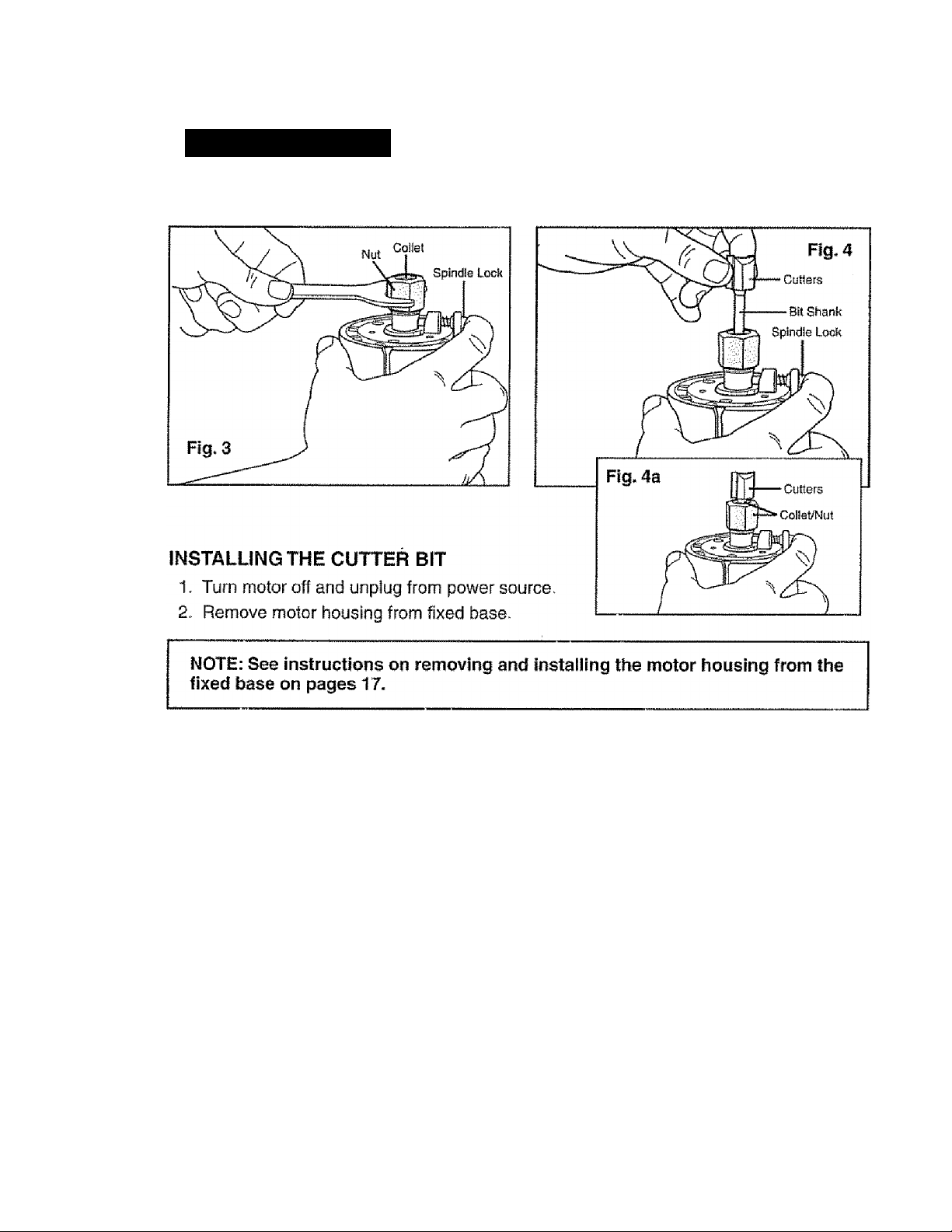
installing and removing the cutting bit (Figs. 3,4 and 4a)
3. Set the motor upside down on its top cap, with collet/nut pointing up.
4. Press spindie lock button to engage and lock the spindle shaft and collet/nut, (Fig. 3),
5. Place the wrench on the collet/nut and turn counter-clockwise and loosen coflei/nut
slightly to accept cutter bit shank,
6. Insert cutter bit shank into collet/nut assembly as far as it will go, then back the shank
out until the cutters are approximately 1/8 to 1/4-inch away from the face of the
collet/nut (Fig. 4, 4a)
7. With cutter bit inserted and spindle lock button pressed in engaging shaft, place wrench
on collet/nut and turn clockwise until router cutter bit and collet/nut are firmly tightened.
WARNING: TIGHTEN collet/nut securely to prevent the cutter bit
A
from slipping. If the collet/nut Is not securely tightened, the cutter bit may detach
during use, causing serious personal injury
NOTE: To ensure proper gripping of cutter bit shank and minimize run-out, the
shank of the cutter bit must be inserted into the collet/nut at least 5/8-inch.
A CAUTION : To prevent damage to tool, do not tighten collet/nut without
a cutter bit installed.
15
Page 16

ASSEMBLY cont.
REMOVING THE GUTTER BIT (Figs. 3 and 4 see page 15)
1. Turn motor off and unplug from power source.
2. Remove motor from fixed base.
3. Set the motor upside down on its top cap, with cotlet/nut pointing up.
4. Press spindle lock button to engage and lock the spindle shaft and coliet/nut, {Fig, 3),
5. Place the wrench on the coliet/nut and turn counter- clockwise and loosen collet/nut
slightly and remove cutter bit shank.
COLLET/NUT CARE
From time to time, inspect the coliet/nut to make sure it is clean and is gripping the cutter
bit properly.
With the router cutter bit removed, turn the collet/nut counterclockwise (with spindle lock
engaged) until it is free from motor's spindle shaft.
Blow the coilet out with compressed air, and clean the tapered Inside of the cotiet/nut with
a tissue or fine brush.
Always make sure the cutter bit shank, coHet/nut and motor spindle are clean and free of
woodchips, dust, residue, grease and rust before instailing.
Apply a slight amount of machine oil to spindie shaft If it looks dry.
Replace worn or damaged coiiets/nuts immediately.
NOTE: The collet/nut Is self-releasing; it is NOT necessary to strike the
collet/nut to free the router cutter bit. If cutter bit seems stuck after use, loosen
collet/nut a little more until it releases.
CUTTER BITS
Get faster, more accurate cutting results by keeping cutter bits clean and sharp. Remove
all accumulated pitch and gum from cutter bits after each use.
When sharpening cutter bits, sharpen only the inside of the cutting edge. Never grind the
outside diameter. Be sure, when sharpening the end of a cutter bit, to grind the clearance
angle the same as originally ground.
INSTALLING ROUTER MOTOR IN BASE
A, WARNING: NEVER use the router motor without installing it into
either a fixed or plunge approved base. Failure to do so could result in serious
personal injury and damage to motor.
NOTE: Before installing motor housing in fixed base, have the collet/nut and
router cutter bit you are going to use already installed in motor housing.
See page 15 “INSTALLING AND REMOVING THE CUTTER BIT’.
A WARNING: ALWAYS turn motor off and unplug router from power source
___________
before making any adjustments or installing accessories. Failure to turn rnotor off
and unplug router could result in accidental starting which can cause serious
personal injury.
___________
_
16
Page 17
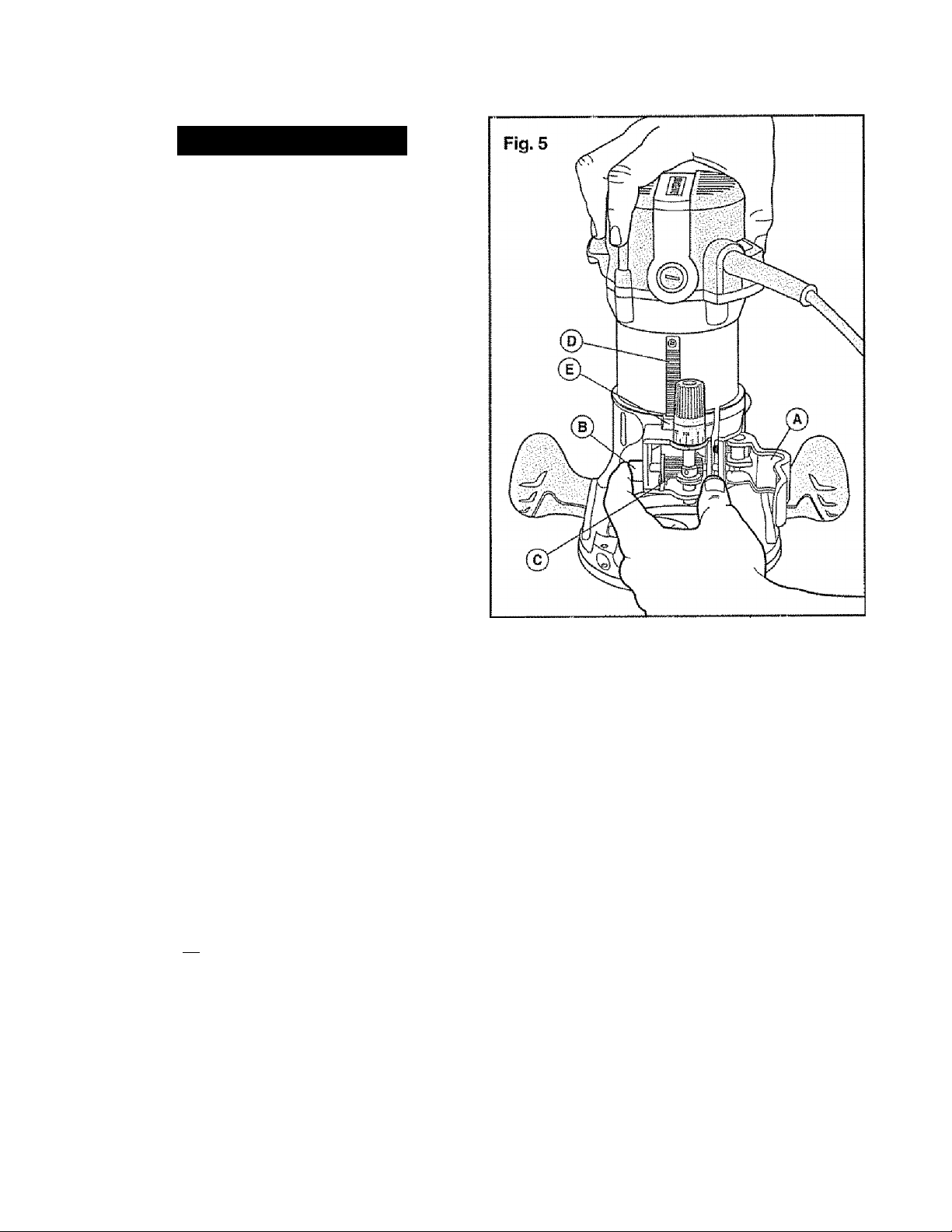
ASSEIVIBLY coni
INSTALLING ROUTER MOTOR
IN BASE (Fig. 5}
1. Turn motor off and unplug
from power source.
2. Place fixed base on flat surface.
3. With back of fixed base facing you,
open motor clamp (A)
4. Press in Coarse Adjustment
Knob (B) to depart the gears (C)
while you align the motor housing's
keystrip (D) with the keystrip-slot
(E) in the fixed base.
5. When the motor's keystrip is
aligned and engaged into the
base's keystrip slot, slide the
motor down into the fixed base.
6. The motor will now slide up or
down to set coarse adjustments
when the coarse adjustment knob
is pressed in.
7. After ail adjustments are made,
close the motor clamp securely.
REMOVING MOTOR FROM BASE (see Fig. 5)
1. Turn motor off and unplug from power source.
2. Place router (fixed base/motor housing) on flat surface.
3. With back of router facing you, open the motor damp (A)
4. Push in coarse adjustment knob (B) to release motor housing “keystrip” (C) from
gear in base, while you lift motor free of base.
5. Set motor upside down on its top cap with collet pointing up and remove cutter bit
Store motor and base in case when not being used.
/K WARNING: always remove cutter bits from collst/nut when the router
is not being used. Leaving bits installed could result in an accident causing
serious personal injury.
17
Page 18

OPERATION
adjusting depth of cut
A\ WARNING' Your router should NEVER BE TURNED ON or be connected
to the power source when you are assembling parts, making adjustments,
installing or removing collets / nuts, cutter bits, cleaning or when it is not
in use. Disconnecting the router will prevent accidental starting, which could
cause serious personal injury.
NOTE: All depth adjustments on the Fixed Base must be made with the
motor clamp open.
NOTE: For all Fixed Base Routers, the cutter bit depth equals the amount of the
cutter that is exposed below the surface of the subbase.
The fixed base is designed with a micrometer fine adjustment worm gear system.
When the bit is lowered to the approximate position desired (coarse setting), the system
then can be micro adjusted to the precise depth.
Coarse Adjustment:
Depressing the Coarse Adjustment Knob (B) ailows you to quickly lower or raise the
cutler bit to a larger or approximate depth setting.
Micro Adjustments:
NOTE: Be sure the worm gear system Is engaged before making fine
adjustments. Test it by turning the Fine Adjustment Dial (C) clockwise and
counter-clockwise to see if the bit lowers and raises. If it does not, press in
the Coarse Adjustment Knob and turn the Fine Adjustment Dial until the gears
engage, then reset zero “0” on Depth Indicator Ring (D).
The Depth Indicator Ring (D) located on the Fine Adjustment Diai is marked incremenfally
in 64's. Turning the fine adjustment dial clockwise 180° (1/2 turn), lowers the cutter bit
1/16-inch. One full turn clockwise (360°) zero ”0" to zero “0” lowers the bit 1/8-in„
The incremental lines between the 64th marks are 1/128's for super fine micro adjustments.
The system allows a maximum of 7 full 360° revolutions, clockwise, to lower the cutter
bit 7/8-in.
The Depth Indicator Ring may be reset to zero “0” without moving the fine adjustment dial.
This allows the user to begin adjustments from any reference point desired.
18
Page 19
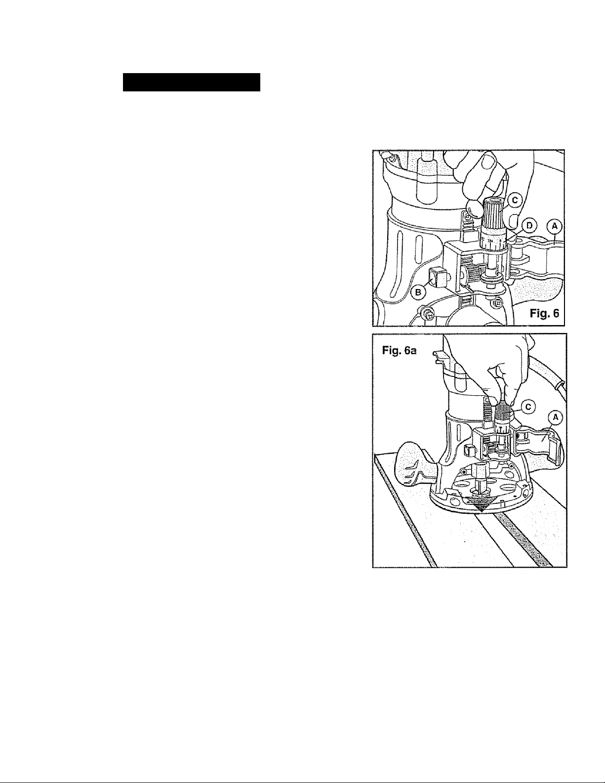
OPERATION cont.
To Adfust Depth (Figs, 6 and 6a)
1, Turn motor off and unplug from
power source,
2. Place router on a flat, level surface
with back of fixed base facing you.
Open Motor Clamp (A).
3, With the cutter bit already installed,
Press in Coarse Adjustment Knob (B),
and lower motor into base until the
cutter bit very close to the flat surface
the base is sitting on,turn
Adjustment Dial (C) until cutter bit
“jusf touches the flat surface the base
is sitting on Then lock Motor Clamp (A).
4. While continuing to press the Coarse
Adjustment Knob (B), turn the
Fine Adjustment Dial (C) until
ZERO “0” mark on Depth Indicator
Ring{D) is lined up with the 1” mark
on base.
Fine
6. Release the Coarse Adjustment Knob,
making sure the “0” stays lined
up with the mark-
6. Place the router on two level scrap
workpieces, positioned so the cutter bit
can be lowered below the subbase
(see Fig. 8).
7. Turn the Fine Adjustment Dial (C)
clockwise to lower the bit to the
desired depth of cut. Turn the dial
counterclockwise to raise the cutter bit.
8. Once your depth of cut is set, close
the motor clamp (A) securely
NOTE: Making a single deep cut is never advisable. Smaller diameter cutter bits
are easily broken by too much side thrust and torque. Larger cutter bits will
cause a rough cut and be difficult to guide and control. For these reasons,
DO NOT EXCEED 1/8-lN. DEPTH OF CUT in a single pass.
19
Page 20
OPERATION coni.
The proper cutting depth, (for each pass), is always determined by the material,
the cutter bit size and type, and the power of the motor.
Always make several progressively deeper cuts by starting at one depth and then make
several passes, each time increasing the cutting depth until your desired depth is reached.
Making a cut that is too deep will stress the motor and the cutter bit, and it may burn the
workpiece and dull the cutter bit. It could also “grab" too much of the workpiece and
cause you to lose control of the router, causing a serious accident.
To be certain that your depth settings are as desired, always make test cuts in scrap
material similar to your workpiece before beginning your final cutting.
Remember, knowing the right depth for each cut comes with routing experience.
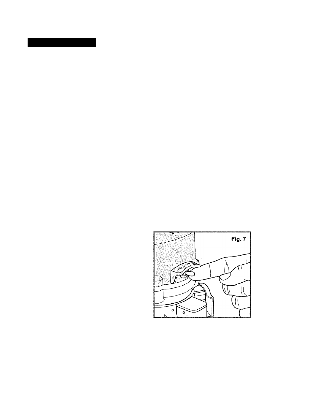
TOGGLE “ON/OFF” SWITCH (Fig. 7)
Your router motor is turned “ON” and "OFF” by the toggle switch located
on the top cap of the motor housing.
The left side of the toggle switch hood (as you face it) is marked‘T’ for “On" and
the right side (as you face it) Is marked “O” for “Off.
TO TURN THE MOTOR “ON”, Push the toggle switch to the left side marked “I”, or “On”
TO TURN THE MOTOR "OFF” Push the toggle switch to the right side marked “0”, or “Off.
Always hold the router and cutter bit away from
the workpiece when turning the toggle switch
"On”. Only contact the workpiece with the
router and cutter bit after the router has reached
full speed. ONLY remove the router and cutter
bit from the workpiece AFTER turning the router
motor “OFF”, and the cutter bit comes to a
complete stop.
Operating in this manner will increase toggle
switch and motor life, and will increase
the quality of your work.
The soft start feature minimizes torque twist, customary in larger router motors,
by limiting the speed at which the motor starts. This increases the motor's life.
20
Page 21
OPERATION coni.
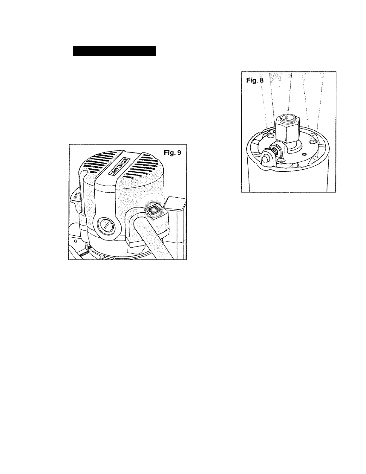
LED WORKLIQHTS (Fig. 8)
Your router motor has 3 built-in worklights located
around the coi!et/nut to provide high visibility of
workpiece when cutting. These lights are always
“On" when the toggle switch is in the “On “ position.
“LIVE TOOL INDICATOR” LIGHT (Fig. 9)
Your router also has a “LIVE TOOL INDICATOR”
green light, located on the motor housing
top cap where the power cord enters the motor
housing. This green light is always on when
router motor is plugged into power source.
PI prii ITPP r^MTri THP WnPICPIPf^P QTikPTINfi TMP f^llT
1 jlw«jlr^<w/11 I i H im SftiwrlwiF I tewi* Vnri« 1 Vmit I I I Im W 1 1 11«\«/Iwiiiit %tf i JTm t I i IIV\iin I f I iwiM i
A WARNING: Before operating your router follow all safety instructions
in this manual. Failure to do so could result in serious personal Injury.
NOTE: Making test cuts is essential with most routing applications. Even with
careful set-ups you won't know exactly how the cut will go until you try it out
A test cut will give you a feet for the set-up, the router's speed, the depth of
cut and how the cutter bit reacts to the workpiece.
Much of routing is a trial-and-error process of making various adjustments,
followed by test cuts as you become familiar with ali of your router's
operational abilities. To avoid ruining good material, make your test cuts on
scrap materials.
Placing your router onto a workpiece (starting the cut) with a fixed base depends on the
type of routing you are going to produce: Edge Routing or Internal Routing
21
Page 22
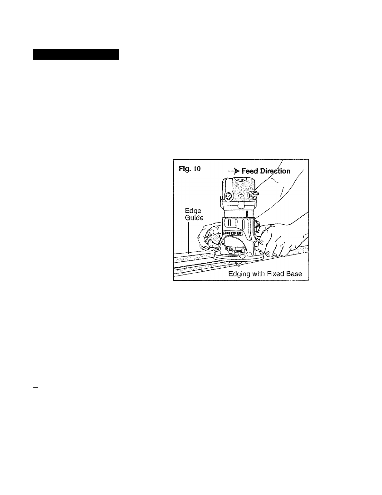
OPERATION cont.
EDGE riOUTING OR INTERNAL ROUTING
For ease of operation and to maintain proper control, your router has two handles,
one on each side of the router base. When operating the router, always hold it firmiy
with both hands (see Fig, 10).
Turn the router “On”, let the motor build to its full speed, then gradually feed the
cutter bit into the workpiece. ALWAYS be alert and watch what you are doing.
NEVER operate the router when you are fatigued.
EDGE ROUTING (Fig. 10)
1. With depth-of-cut set, place router
on edge of workpiece, making sure
the cutter does not contact
the workpiece.
2, Have an edge guide (board or meta!
straightedge) clamped in place to help
guide router's base when making
your edge cut.
3 router “On”, and let the
motor build to its full speed.
4. To begin your cut, gradually feed the
cutter bit into the edge of the workpiece.
5. When cut is completed, turn motor “Off and let cutter bit come to a complete stop
before removing it from the workpiece.
6. Unplug router from power source, place router upside down on worktable, and inspect
finished cut in workpiece.
A WARNING; Always securely clamp your workpiece and keep a firm grip
on the router base with BOTH HANDS at ail times. Failure to do so could result
in loss of control causing possible serious personal injury.
A WARNING: Removing cutter bit from workpiece while it is still rotating
could damage workpiece and result in loss of control, causing serious persbhal
Injury.
NOTE: Making test cuts in scrap material that is similar to your workpiece is
essential. Learning how the router’s speed, depth-of-cut and cutter bit will react
in the workpiece will help you produce quality cuts.
22
Page 23
OPERATION coni.
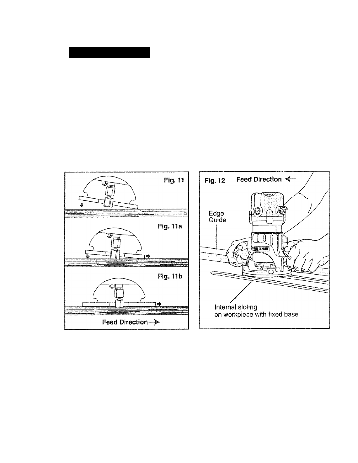
INTERNAL ROUTING (Figs. 11,11a, 11b and 12)
1 „ With depth-of-cut set, tilt router and place on workpiece with leading edge of sub-base
contacting workpiece first (Fig, 11),
2- Turn motor “On” and let motor build up to its full speed, being careful not to let cutter bit
contact workpiece.
3. To begin your cut, gradually feed the cutter bit into the workpiece until the subbase
is level with the workpiece (see Fig 11a, 11b).
4. When cut is completed, turn motor “Off and let cutter bit come to a complete stop
before removing it from the workpiece.
5. Unplug router from power source, place router upside down on worktable, and inspect
finished cut in workpiece.
A WARNING: Always securely clamp your workpiece and keep a firm grip
on the router base with BOTH HANDS at all times. Failure to do so could result in
loss of control causing possible serious personal injury. if using a router table,
large cutter bits should be used for edging only.
A WARNING: Removing cutter bit from workpiece while It is still rotating
could damage workpiece and result In loss of control, causing serious personal
injury.
23
Page 24
OPERATION cont.
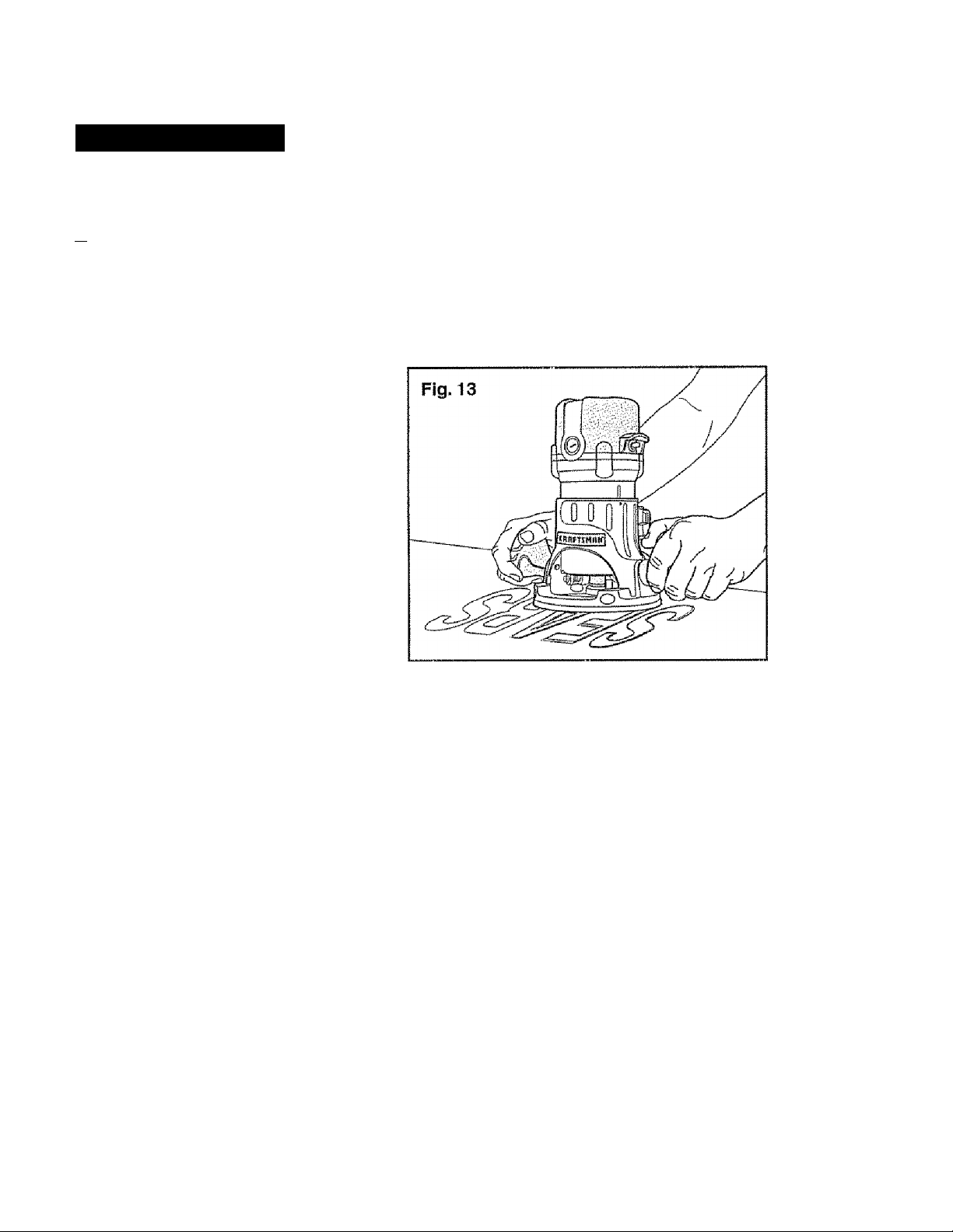
FREEHAND ROUTING WITH THE FIXED BASE (Fig. 13)
A WARNING: Do not use large cutter bits for freehand routing. Use of large
cutter bits when freehand routing could cause loss of control or create other
hazardous conditions that could result in personal injury. If using a router table,
large bits should be used for edging only.
When used freehand, the router becomes
a flexible and versatile tool This flexibility
makes it possible to easily rout signs,
relief sculptures, etc.
When freehand routing;
1. Draw or layout the pattern on
the workpiece.
2. Choose the appropriate bit.
3. Rout the pattern in two or more
passes. Do not exceed 1/8-in depth
of cut in a single pass. This will
help provide better control as well as
serve as a guide on the next passes.
NOTE; A core box or V-groove bit is often used for routing letters and engraving
objects. Straight bits and ball mills are often used to make relief carvings. Veining
bits are used to carve small, intricate details.
NOTE: Making a single deep cut Is never advisable. Smaller diameter bits
are easily broken by too much side thrust and torque. Larger bits will cause
a rough cut and be difficult to guide and control. For these reasons,
00 NOT EXCEED 1/8-IN. DEPTH OF CUT in a single pass.
A WARNING: Always securely clamp your workpiece and keep a firm grip
on the router base with BOTH HANDS at all times. Failure to do so could result
in loss of control causing possible serious personal injury.
24
Page 25
OPERATION com.
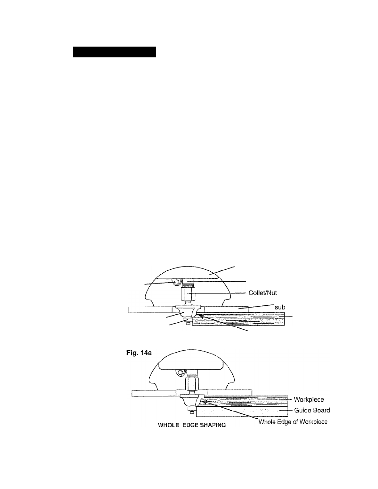
EDGING WITH A PILOT BIT (Figs. 14 and 14a)
The arbor-type bits with pilots are excelieni for edge shaping of any workpiece edge that
is either straight, or curved at a curvature as great or greater than the radius of the bit to
be used. The pilot prevents the bit from making too deep a cut; and holding the pilot firmly
in contact with the workpiece edge throughout prevents the cut from becoming too shallow.
Whenever the workpiece thickness, together with the desired depth of cut (as adjusted by
router depth setting) are such that only the top part of the edge is to be shaped (leaving at
least a 1/16-in. thick uncut portion at the bottom), the pilot can ride against the uncut
portion, which serves to guide it (see Ftg. 14).
If the workpiece is too thin or the bit set too low so that there will be no uncut edge to ride
the pilot against, an extra board to act as a guide must be placed under the workpiece
(see Fig, 14a). This “guide” board must have exactly the same contour - straight or curved as the workpiece edge. If it is positioned so that its edge is flush with the workpiece edge,
the bit wiil make a full cut (in as far as the bit radius). On the other hand, if the guide is
positioned as shown in Fig. 14a (out from the workpiece edge), the bit will make less than
a full cut - which will alter the shape of the finished edge.
NOTE: The size (diameter) of the pilot that is used determines the maximum cut
width that can be made with the pilot against the workpiece edge (the small pilot
exposes all of the bit; the large one reduces this amount by 1/16-In.). Any of the
piloted cutter bits can be used without a pilot for edge shaping with guides.
Fig. 14
Spindle Lock
Cutter-bit
Pilot
TOP EDGE SHAPING
Motor Housing
Spindle
Fixed Base
base
Workpiece
Top Edge of Workpiece
A WARNING: Always securely clamp your workpiece and keep a firm grip
on the router base with BOTH HANDS at all times. Failure to do so could result
in loss of control causing possible serious personal injury.
25
Page 26
OPÉRATION cont.
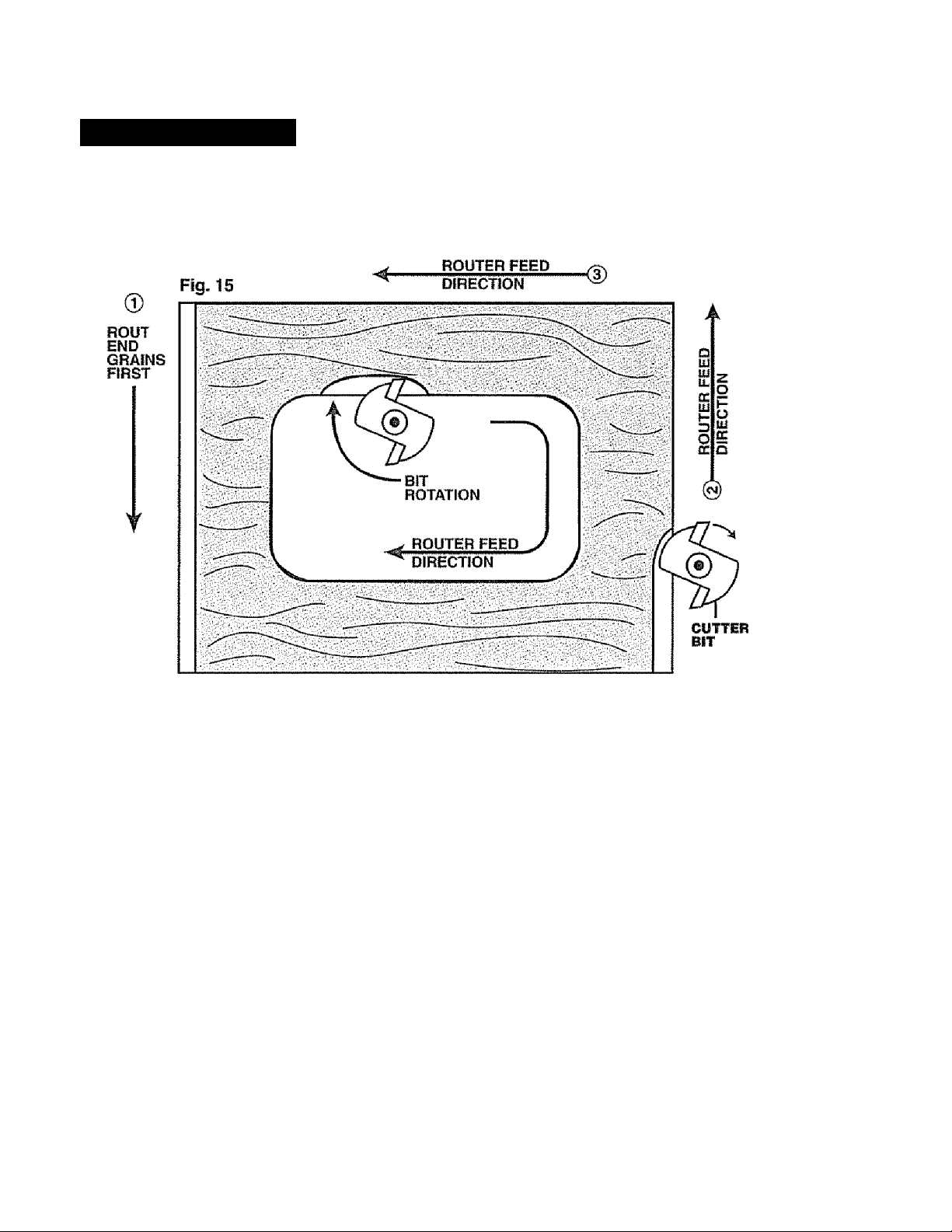
feeding THE ROUTER (Fig. 15)
The secret to professional routing is in making a careful set-up for the cut, selecting the
proper depth of cut, knowing how the cutter bit reacts in your workpiece, and the rate and
direction of feed of the router.
ROUTER FEED
0-
DIRECTION
DIRECTION OF FEED - EXTERNAL CUTS (Fig. 15)
The router motor and cutter bit rotate clockwise. This requires the feed of the cutter bit to
be from left to right (see Fig. 15). Feeding the bit from left to right will cause the bit to pull
the router towards (up against} the workpiece.
If you feed the router in the opposite direction (right to left), the rotating force of the
cutter bit will tend to throw the bit away from the workpiece, making it hard to control;
this is called “Climb-Cutting”; cutting in the opposite direction of the proper feed direction.
“Climb Cutting” increases the chance for loss of control, resulting in possible personal
iniury. When “Climb Cutting” is required (backing around a corner for example), exercise
extreme caution to maintain control of the router.
Because of the high speed of the cutter bit during a proper feeding operation (left to right),
there is very little kickback under normal conditions. However, if the cutter bit strikes a knot,
an area of hard grain in the wood workpiece, or a foreign object, the normal cutting action
couid be affected and cause “Kickback”,
This Kickback may cause damage to your workpiece, and could cause you to lose control
of the router, causing possible persona! injury. Kickback is aiways in the opposite direction
of the clockwise cutter bit rotation, or counterciockwise.
To guard against and help prevent Kickback, plan your set-up and direction of feed so
you're always thrusting the router, keeping the sharp edges of the cutter bit continuously
biting straight into new (uncut) wood (workpiece). Also, always inspect your workpiece for
knots, hard grain, and foreign objects that couid cause a kickback problem.
26
Page 27
OPERATION cont.
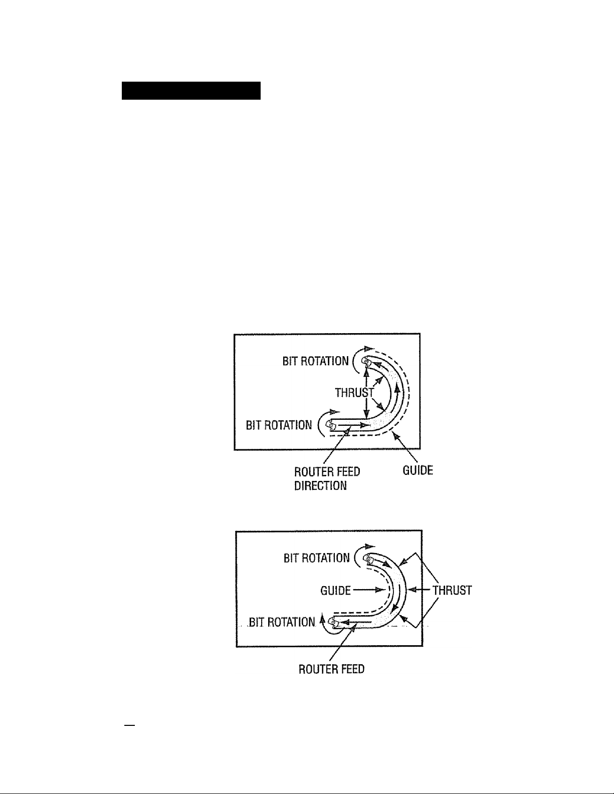
direction of feed ” INTERNAL CUTS {Figs. 16 and 16a)
When making an internai cut, such as a groove, dado or slot, always have the guide you
are using with the router (edge guide, straight edge, board guide), on the right-hand side
of the router as you make your cut, see Fig. 16),
When the guide Is positioned on the right hand side of the router, the router travel should
be from left to right and "counterclockwise” around curves (see Fig. 16). This counterclockwise
action around the curve could cause “Climb cutting”. Always be alert and exercise extreme
caution to maintain control of the router when making this type of cut around curves.
When thé guide is positioned as shown in Fig 16a, the router travel should be from left to
right and clockwise around curves
If there is a choice, the set-up in Fig. 16 is easier to use, but there is the possibiiity of
“Climb Cutting” around curves. In either case, Fig. 16 or Fig. 16a, the sideways thrust of
the router cutting is always against the guide, as is proper.
Fig. 16 GUIDE OUTSIDE
Fig. 16a GUIDE INSIDE
DIRECTION
A WARNING: Always securely clamp your workpiece and keep a firm grip
on the router base with BOTH HANDS at all times. Failure to do so could result
in loss of control causing possible serious personal iri|ury.
27
Page 28
OPERATION cbrit.
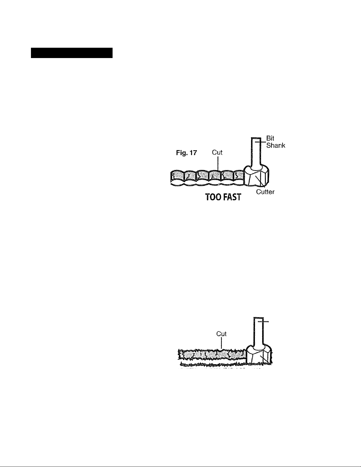
RATE OF FEED (Figs. 17 and 17a)
The proper rate of feed depends on several factors: the hardness and moisture content
of the workpiece, the depth of cut, and the cutting diameter of the bit. When you are
cutting shallow grooves in soft woods such as pine, you may use a faster rate of feed.
When making deep cuts in hardwoods such as oak, you should use a slower rate of feed.
FEEDING TOO FAST (Fig. 17)
Clean and smooth finished cuts can only
be achieved when the cutter bit is rotating
at a relatively high speed, taking very small
bites, producing tiny, dean cut chips.
Forcing the feed of the cutter bit forward too
fast slows the RPM of the cutter bit, and the bit
takes bigger bites as it rotates. Bigger bites
mean bigger chips and a rough finish.
This forcing action can also cause the
router motor to overheat.
Under extreme force-feeding conditions, the RPMs can become so slow and the bites
become so large that chips become partially cut off, causing splintering and gouging
of the workpiece.
The router will make clean, smooth cuts if allowed to run freely without the overload of
forced feeding. You can detect forced feeding by the sound of the motor. Its usual
high-pitched whine will sound lower and stronger as it loses speed. Holding the router
against the workpiece will also be strained and harder to do.
FEEDING TOO SLOW (Fig. 17a)
When you feed the cutter bit too slowly,
the rotating cutter bit does not cut into
new wood fast enough to take a bite,
instead, it scrapes away sawdust-like
particles. This scraping produces heat,
which can glaze, burn and mar the cut
in the workpiece and, in extreme cases,
overheat the cutter bit.
When the cutter bit is scraping instead
of cutting, the router is more difficult to
control as you feed it.
With almost no load on the motor, the cutter bit has a tendency to bounce off the sides of
the cut in the workpiece, producing a cut with a rippled finish instead of clean straight sides.
Fig. 17a
TOO SL OW
Bit
Shank
Cutter
28
Page 29
OPERATION coni
valili will EÌmÌmÌLf wI**I l«wiCw I Vrini I nitl« iOl
ri r^trci crr^^mo /CiM -I Ci\
\ /
A WARNING; ALWAYS wear eye protection.
The chip shield deflector is not intended as a safety guard.
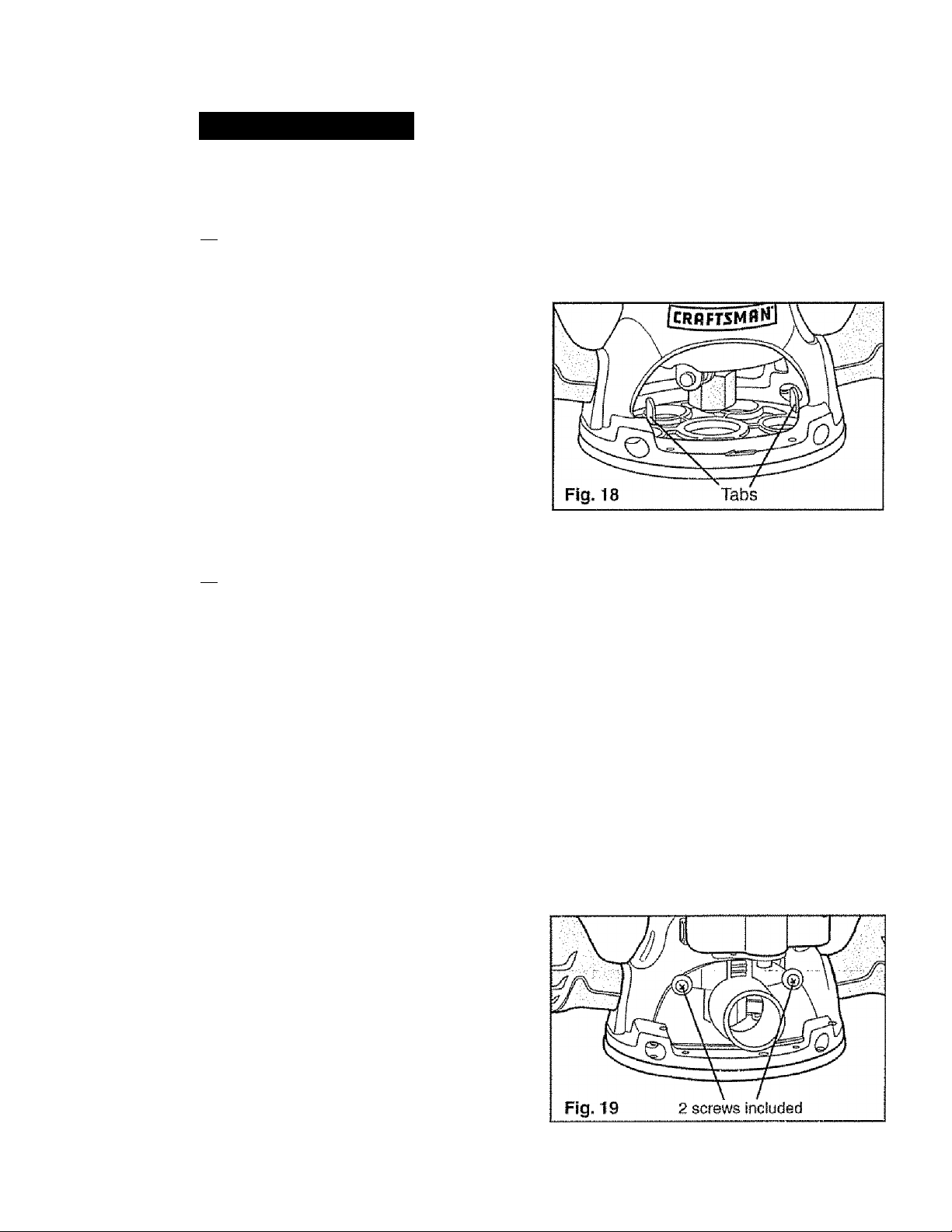
To remove chip shield from fixed base, press
inward on tabs until chip shield releases from
base and remove it To attach, place chip shield
back in position and flex sides while pushing it
in until it snaps back into place (See Fig. 18).
A WARNING: The chip shield deflector helps keep dust and chips away from
the operator; it will not stop objects larger than woodchips thrown from the bit.
CAUTION: ALWAYS have the chip shield deflector in place on the base when
operating the router.
_______________
A WARNING: ALWAYS turn motor off and unplug router from power source
before making any adjustments or installing accessories. Failure to turn motor off
and unplug router could result in accidental starting which can cause serious
personal injury.
DUST COLLECTION WITH DUST EXTRACTION HOOD (Fig. 19)
There Is a dust extraction hood included
with this router. The hood Is sized to
accept a lV4-in. vac hose adapter,
sold separately.
To attach the hood onto the fixed base,
position and secure it to the back of the base
with the two screws (included) as shown
in Fig. 19.
29
Page 30

MAINTENANCE
A WARNING: To ensure safety and reliability, all repairs should be performed
by a qualified service technician at a Sears Service Center.
GENERAL
Only the parts shown on the parts iist are intended for repair or replacement by the
customer. All other parts represent an important part of the double insulation system
and should be serviced only be a qualified Sears® service technician.
A WARNING: For your safety, ALWAYS turn off switch and unplug router
motor from the power source before performing any maintenance or cleaning.
It has been found that electric tools are subject to accelerated wear and possible
premature failure when they are used to work on fiber glass boats and sports cars,
wallboard, speckling compounds or plaster.. The chips and grindings from these materials
are highly abrasive to electrical tool parts, such as bearings, brushes, commutators, etc.
Consequently, it is not recommended that this too! be used for extended work on any
fiberglass material, wallboard, spackling compound or piaster. During any use on these
materials, it is extremely important that the tool is cleaned frequently by blowing with
an air jet
A WARNING: Always wear safety goggles or safety glasses with side shields
during power tool operations, or when blowing dust. If operation is dusty, also
wear a dust mask.
ROUTINE MAINTENANCE
A WARNING: DO NOT at any time let brake fluids, gasoline, petroleum-based
products, penetrating oils, etc. come in contact with plastic parts. Chemicals can
damage, weaken or destroy plastic, which may result in serious personal injury.
1. When work has been completed, clean the tool to allow smooth functioning of the
tool over time.
2. Use dean damp cloths to wipe the tool.
3. Check the state of all electrical cables.
4. Keep the motor air openings free from oil, grease and sawdust or woodchips, and
store tool in a dry place.
5. Be certain that all moving parts are well lubricated, particularly after lengthy exposure
to damp and/or dirty conditions.
A WARNING: For your safety, ALWAYS turn off switch and unplug router
motor from the power source before performing any maintenance or cleaning.
Refer to Collet/Nut Care and Cutter Bits on page 16 for cleaning care.
30
Page 31
MAINTENANCE cont.
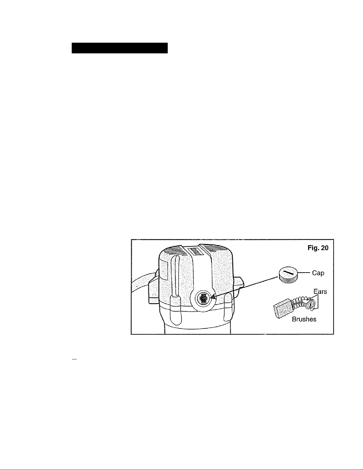
REPLACEWIENT OF CARBON BRUSHES {Fio. 20)
Replacement brush sets are available through Sears Parts and Repair Centers.
1. Unplug the router motor before inspecting or replacing brushes,
2. Replace both carbon brushes when either has less than 1/4-in. length of carbon
remaining, or if the spring or wire is damaged or burned.
3, Using a slotted screwdriver, remove the black plastic cap on each side of the router
motor (Fig. 20) and carefully withdraw the spring-loaded brush assemblies. Keep
brushes clean and sliding freely in their guide channels.
fjlQ-fE; reinstall the same brushes, make sure the brushes go back in the
same way they came out. This will avoid a break-in period.
4, Insert new brush assemblies into guide channels, with the carbon part going in first,
being certain to fit the two metal “ears” into their siots in the channel (Fig. 20).
5 Remember to replace both end caps after inspecting or servicing brushes. Tighten the
caps snugly, but do not over-iighten. The router should be allowed to “RUN IN” (run at
no load without a cutter bit) for 5 minutes before use, to seat the new brushes property.
A WARNING: For your safety, ALWAYS turn off switch and unplug router
motor from the power source before performing any maintenance or cleaning.
LUBRICATION
All of the bearings in this tool are lubricated with a sufficient amount of high-grade
lubricant for the life of the tool under normal operating conditions. Therefore, no further
lubrication is required.
31
Page 32
ACCESSORIES
A WARNING: The use of attachments or accessories that are not
recommended for this tool might be dangerous and could result in serious injury.
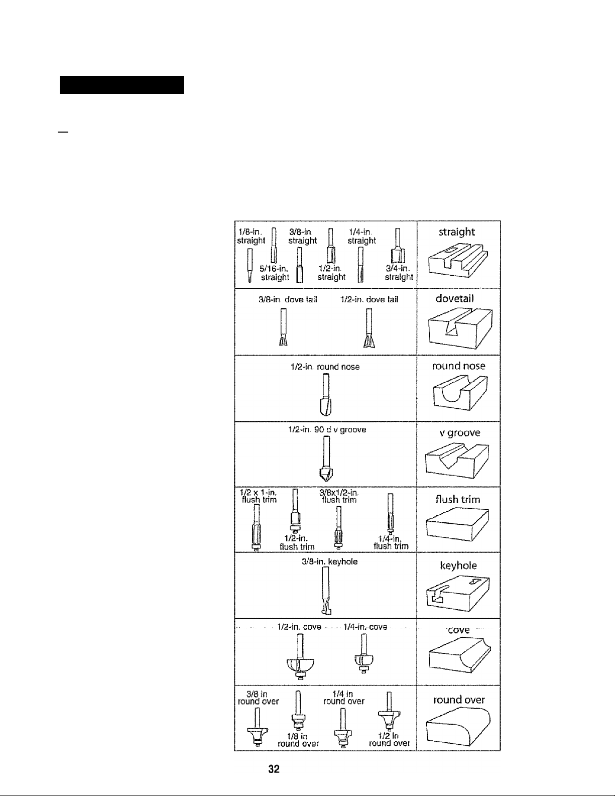
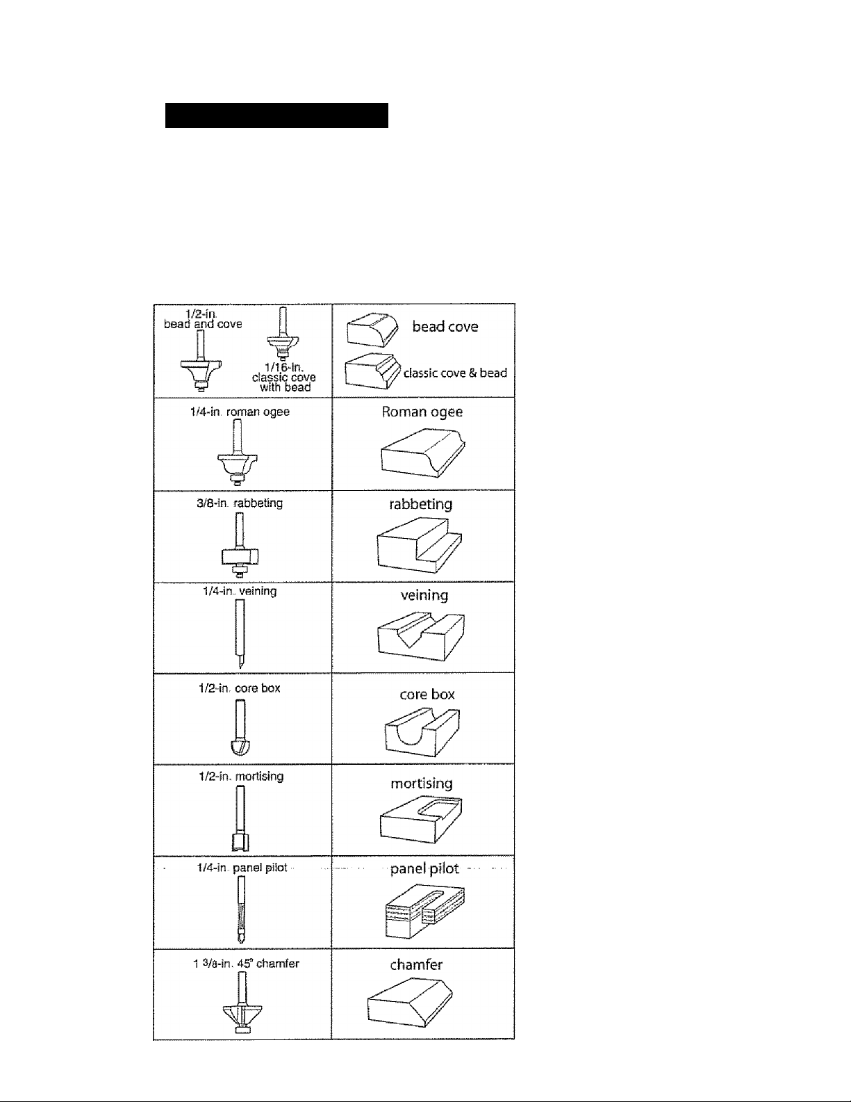
Sears and other Craftsman® outlets offer a large selection of Craftsman router
accessories designed for specific routing applications.
There is a large selection of
Craftsman Router Cutter Bits
available in High-Speed Steel
or Carbide Tipped High-Speed
Steel for all your routing needs,
shown to the right is an example
of bits available.
Page 33
ACCESSORiES cont.
In addition to a wide variety of router bits, Sears also offers accessories such as:
Router tables, various template sets, universal router fence with lock knobs (64181),
11 pc. bushing set (64180) and clear sub-base sets; 6pc. fixed base (64182)
6 pc. plunge base (64183).
33
WARNING: Only use
router tables with proper
guarding for the cutter bit
and with “on-board” switch
controlled receptacles.
Failure to use router tables
with appropriate safety
features could result in
serious personal injury.
Page 34
PARTS LIST
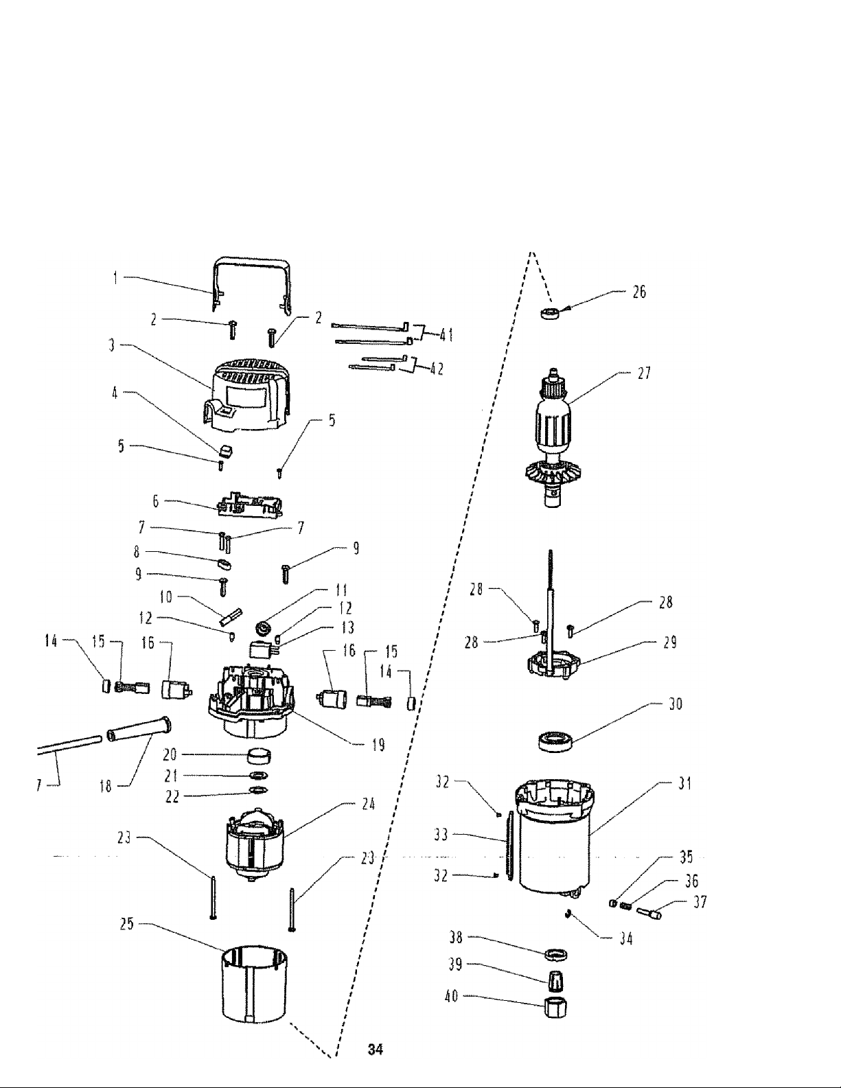
9.5 Amp/13/4 Peak HPMODEL NUMBER 320.17541
The Model Number will be found on the Nameplate.
Always mention the Model Number in ail correspondence regarding your tool.
Motor Unit
Page 35
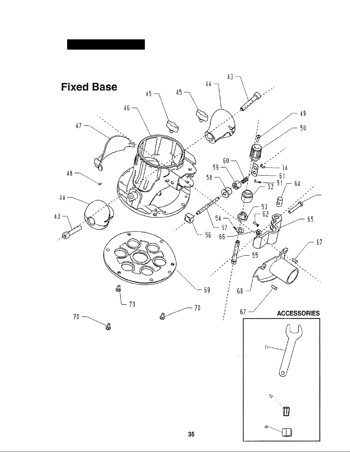
PARTS LIST cont.
9.5 Amp /13/4 Peak HP MODEL NUMBER 320.17541
The Model Number will be found on the Nameplate.
Always mention the Model Number in all correspondence regarding your tool.
6 3
Page 36

PARTS LIST corit.
9.5 Amp /1 3/4 Peak HP Fixed Base Router
MODEL NUMBER 320.17541
The Model Number will be found on the Nameplate,
Always mention the Model Number in all correspondence regarding your tool.
Item No. Parts No. Part Description
1
2 5610059000
3 3121517000
4 3121518000
5 5610017000
6 4890064000 PCB Plate
7 5610106000
8 3120134000 Cord Anchorage
9
10
11 3122851000
12 5620017000 Screw 2
13
14 3120537000
15 4960019000
16 2800005000
17 4810002000
18 3121050000 Cord Guard
19 3121494000 Middle Housing
20
21 3121049000
22 3700249000 Gasket
23
24
25
26 5700008000
27 2760719000
28 5620040000
29 2820887000
30 5700056000
31
32 5620062000 Screw
33
34 5660005000 Ring
35
36 3660174000
37 3550592000
38 5630179000
39
40 5630187000
3700788000 Decorate Cover 1
Screw
Rear Cover
Transparent Cap 1
Screw 2
Screw
5610059000
Screw 2
4540017000 Power Indicator Light 1
Seal Ring
4870073000 Switch 1
Brush Cap 2
Carbon Brush 2
Brush Holder 2
Power Cord 1
3520130000
Bearing Holder 1
Gasket
5610048000 Screw 2
2740116000 Stator ■ 1
3121495000
1 dl 1 OcUiit::^ 1
Bearing 1
Rotor 1
Screw 3
1. FtO
Bearing 1
3420356000 Housing
3520227000
Gear Rack i 1
3520131000 Bush 1
Stop Spring 1
Spindle Lock 1
Nut 1
3550721000 Collet 1
Collet Nut 2
Qty.
2
1
1
2
1
1
1
1
1
1
1
1
2
36
Page 37

PARTS LiST cont.
9.5 Amp /13/4 Peak HP Fixed Base Router
MODEL NUMBER 320.17541
The Model Number will be found on the Namepiate.
Always mention the Model Number in all correspondence regarding your tool
Item No.
41 2822039000 Internal Wire
42 2822038000 Internal Wire
43
44
45 3400189000
46 3420396000 Mounting
47 3121637000 Chip Shield
48
49
60
51 3121539000
52 3121647000
53 3550615000 Worm
54 5650172000 Plate
56
56 3121648000
57
58 3520141000 Gear
eri
Ob? 3520147000 Lock Gear
60
61 3700848000
62 5620065000
63 56S0332000 Screw
64 3550596000 Lock Pin
65
66 5630015000
67
68
69 3122924000 Mounting Plate 1
70
71
72 355059500Ò Collet
Parts No. Part Description Qty.
5620024000 Screw
3121635000 Handle 2
Lock Bolt
5670040000 Located Pin 1
5620041000 Screw , 1
3121646000 Adjusting Knob 1
Rubber Pole
Indicator Ring
3550613000 Shaft 1
Button 1
355057’gOÒÒ
3660167000 Spring
3420395000 Clamping Lever 1
5620040000
Q-i 00”7D/innn
5620049000 Screw 3
3700807000 Wrench 1
Cear Shaft
Plate 1
Screw 1
Lock Nut 1
Screw 2
Vaccum Adapter
iC
1
1
2
2
2
0
1
1
1
1
1
1
1
1
1
1
1
1
37
Page 38

NOTES
38
Page 39

NOTES
39
Page 40

’’Ш/
msf
т
щт
IS
■
*8
ш
1Й
шштш
Get ¡t fixed, at your home or ours!
'"IflipiÉ
Your Home
For repair - in your home - of ali major brand appliances,
lawn and garden equipment, or heating and cooling systems,
no matter who made it, no matter who sold it!
For the replacement parts, accessories and
owner's manuals that you need to do-it-yourself
For Sears professional installation of home appliances
and items like garage door openers and water heaters
'j.800-4«iVIY-HOrViE® Anytime, day or night
(1-800-469-4663) (U.S A and Canada)
www.sears.com www.sears.ca
Our Home
For repair of carry-ln products like vacuums, lawn equipment,
and electronics, call or go on-line for the nearest
Sears Parts and Repair Center.
1 “800-488-1222 Anytime, day or night (U.S A only)
www.searsxom
To purchase a protection agreement (U.S.A)
or maintenance agreement (Canada) on a product serviced by Sears
1-800-827-66S5 (U S A) 1-800-361-6665 (Canada)
Para pedir servicio de reparación
a domicilio, у para ordenar piezas.
1-888-SU-HOGAR®
(1-888-784-6427)
Au Ganada pour service en français:
1-800-LE-FOYER^^
(1-800-533-6937)
wwwsears.ca
OS^rs Brands, U.C
® Registered Trademark Trademark / ^ Service Mark of Sears Brands, LLC
® Marca Registrada /™ Marca de Fábrica / Marca de Servicio de Sears Brands, LLC
Marque de commerce / ***° Marque déposée de Sears Brands, LLC
 Loading...