


Operator's Manual
®
42" SNOW BLADE
Model No. 486.244414
STOP
DO NOT RETURN TO STORE
For Missing Parts or Assembly Questions Call 1-866-576-8388
CAUTION:
Before using this product, read and follow all Safety, Assembly and Operating Instructions
IMPORTANT: For Missing Parts or Assembly Questions Call 866-576-8388
•Safety
•Assembly
•Operation
•Maintenance
•Parts
Want more information or assembly tips? Scan for Video Instruction Guide.
Sears Brands Management Corporation, Hoffman Estates, IL 60179 U.S.A. www.sears.com/craftsman
PRINTED IN U.S.A. |
FORM NO. 41793 (12/15/14) |

TABLE OF CONTENTS
WARRANTY.................................................................... |
2 |
SAFETY RULES.............................................................. |
2 |
ACCESSORIES AND ATTACHMENTS........................... |
3 |
FULL SIZE HARDWARE CHART.................................... |
3 |
CARTON CONTENTS..................................................... |
4 |
ASSEMBLY................................................................ |
5-13 |
OPERATION............................................................. |
14-15 |
MAINTENANCE............................................................. |
15 |
SERVICE AND ADJUSTMENTS.................................... |
16 |
STORAGE................................................................. |
16 |
TROUBLESHOOTING............................................... |
17 |
REPAIR PARTS ILLUSTRATION...................................... |
18 |
REPAIR PARTS LIST................................................ |
19 |
PARTS ORDERING/SERVICE............... |
BACK COVER |
SAFETY
Any power equipment can cause injury if operated improperly or if the user does not understand how to operate the equipment. Exercise caution at all times when using power equipment.
•Read the tractor and snow blade owner's manuals and know how to operate your tractor before using tractor with snow blade attachment.
•Never operate tractor and snow blade without wearing proper clothing suited to weather conditions and operation of controls.
•Never allow children to operate tractor and snow blade, and do not allow adults to operate without proper instructions.
•Always begin with transmission in first (low) gear and gradually increase speed as conditions permit.
Look for this symbol to point out important safety precautions.It means — Attention!! Become alert!! Your safety is involved.
WARRANTY
CRAFTSMAN LIMITED WARRANTY
FOR ONE YEAR from the date of sale this product is warranted against defects in material or workmanship. WITH PROOF OF SALE a defective product will be replaced free of charge. For warranty coverage details to obtain free replacement, visit the web page: www. craftsman.com/ warranty To obtain warranty coverage, return a defective product with proof of sale to the retailer from which it was purchased for free replacement. This warranty is void if this product is ever used while providing commercial services or if rented to another person.This warranty gives you specific legal rights, and you may also have other rights which vary from state to state.
Sears Brands Management Corporation, Hoffman Estates, IL 60179
DO NOT RETURN TO STORE for Missing Parts or Assembly Questions
Call 1-866-576-8388 Attachment Hotline
The model number and serial numbers will be found on |
MODEL NUMBER: |
486.244414 |
|
a decal attached to the snow blade. |
|||
SERIAL NUMBER: |
__________________ |
||
You should record both the serial number and the |
|||
DATE OF PURCHASE: |
__________________ |
||
date of purchase and keep in a safe place for future |
|||
reference. |
|
|
|
|
|
|
2

FULL SIZE HARDWARE CHART
A |
B |
C |
D |
E |
F |
G |
H |
I
O P S


 J N
J N
T
K
L  Q
Q  R U W
R U W 

M
V


 X Y
X Y
REF. |
PART NO. |
QTY. |
DESCRIPTION |
REF. |
PART NO. |
QTY. |
DESCRIPTION |
A |
46071 |
1 |
Hex Bolt, 1/4-20 x 3-1/4" |
N |
R19172410 |
8 |
1/2" Washer, (Large) |
B |
43648 |
1 |
Hex Bolt, 1/4-20 x 1-1/2" |
O |
43070 |
6 |
3/8" Washer |
C |
43085 |
1 |
Hex Bolt, 5/16-18 x 1-1/2" |
P |
43081 |
4 |
5/16" Washer |
D |
43001 |
14 |
Hex Bolt, 3/8-16 x 1" |
Q |
R19171616 |
1 |
1/2" Washer |
E |
710-0305 |
2 |
Carriage Bolt, 3/8-16 x 1-1/4" |
R |
43003 |
6 |
3/8" Lock Washer |
F |
44326 |
6 |
Bolt, Carriage 5/16-18 x 1" |
S |
44917 |
2 |
Palnut, 3/8" |
G |
47631 |
6 |
Hex Bolt, 3/8" x 1" (Thd. Forming) |
T |
23658 |
1 |
Spacer, 5/8" Long |
H |
43350 |
6 |
Carriage Bolt, 3/8-16 x 1" |
U |
46053 |
2 |
Spacer, 1" long |
I |
48106 |
2 |
Shoulder Bolt, 3/8 x .9" |
V |
43010 |
2 |
Cotter Pin 1/8" x 1-1/4" |
J |
712-0256 |
2 |
Hex Jam Nut, 5/16" Fine Thread |
W |
43055 |
4 |
Hairpin Cotter |
K |
47189 |
3 |
1/4" Nylock Hex Nut |
X |
43082 |
2 |
Lock Nut, 3/8" |
L |
47810 |
7 |
5/16" Nylock Hex Nut |
Y |
43407 |
2 |
Hex Bolt, 3/8-16 x 3/4" |
M |
HA21362 |
18 |
3/8" Nylock Hex Nut |
|
|
|
|
3

PARTS IN PACKAGES NOT SHOWN FULL SIZE
1 |
5 |
6 |
8 |
10 |
|
|
|
|
|
|
4 |
|
7 |
9 |
|
|
|
|
|
2 |
|
|
|
|
|
|
|
|
11 |
|
|
|
|
12 |
|
3 |
|
|
|
REF |
QTY |
PART NO |
DESCRIPTION |
REF |
QTY |
PART NO |
DESCRIPTION |
1 |
2 |
746-0260 |
Cable End Fitting |
7 |
1 |
— |
Blade Adjust Spring |
2 |
1 |
05762 |
Cable Mount Bracket |
8 |
1 |
731-0869 |
Plastic Grip |
3 |
1 |
43348 |
Angle Lock Spring |
9 |
1 |
62561 |
Grip Assembly |
4 |
2 |
726-0178 |
Nylon Tie |
10 |
2 |
23151 |
Angle Lock Bars |
5 |
1 |
23856 |
Spring Mount Rod |
11 |
1 |
46066 |
Blade Pivot Shaft |
6 |
1 |
46065 |
Channel Pivot Pin |
12 |
2 |
24690 |
Skid Shoe |
CARTON CONTENTS (Loose Parts in Carton)
NOTE: Not all supplied parts will be needed for your tractor model. Unused parts may be discarded.
For model 917 tractors |
15 |
|
|
18 |
|
13 |
|
17 |
|
|
|
|
|
|
|
|
|
14 |
16 |
21 |
|
|
|
|
|
|
|
|
|
|
|
For model 247 tractors |
23 |
For model 247 tractors |
|
|
|
|
|
|
|
|
19 |
|
|
24 |
25 |
|
|
|
|
|
|
|
|
26 |
|
|
|
|
20 |
|
22 |
|
|
|
|
|
|
|
|
REF |
QTY |
PART NO |
DESCRIPTION |
REF |
QTY |
PART NO |
DESCRIPTION |
13 |
1 |
27611 |
Hanger Bracket, L.H. (model 917) |
20 |
1 |
— |
Lift Handle Tube |
14 |
1 |
27612 |
Hanger Bracket, R.H. (model 917) |
21 |
1 |
63033 |
Lift Handle Rod |
15 |
1 |
24023 |
Pivot Support Bracket |
22 |
1 |
49808 |
Cable |
16 |
2 |
25647 |
Angle Support Bracket |
23 |
2 |
24520 |
Slotted Angle Support Bracket |
17 |
1 |
— |
Channel Assembly |
24 |
1 |
— |
Mounting Bracket, R.H. (model 247) |
18 |
1 |
— |
Blade Assembly |
25 |
1 |
— |
Mounting Bracket, L.H. (model 247) |
19 |
1 |
48167 |
Blade Pivot Rod |
26 |
2 |
27864 |
Blade Mount Bracket (model 247) |
4

ASSEMBLY
TOOLS REQUIRED FOR ASSEMBLY
(1)Pliers
(1)Hammer
(1)Adjustable Wrench (or socket set)
(1)9/16" Open End or Box End Wrench
(1)7/16" Open End or Box End Wrench
(1)1/2" Open End or Box End Wrench
NOTE: Not all of the supplied parts and hardware will be needed for any one particular tractor. Unneeded items may be discarded after assembly has been completed.
NOTE: Right hand (RH) and left hand (LH) are determined from the operator's position while seated on the tractor.
CAUTION: Do not begin assembling until the tractor engine, muffler and exhaust deflector have been allowed to cool off.
LOCATE MODEL LABEL OF TRACTOR
•Look under your tractor seat, locate the serial number, and proceed to the step as shown.


 ®
®
MODEL |
917. 000000 |
SERIAL |
000000A000000 |
193653
917 MODEL TRACTORS
STAY ON PAGE 5


 ®
®
MODEL |
247. 000000 |
SERIAL |
000000A000000 |
193653
247 MODEL TRACTORS GO TO PAGE 8 (BOTTOM)
INSTRUCTIONS FOR 917 MODELTRACTORS
LOCATE THE MOWER SUSPENSION BRACKETS
•If there is a single mower deck suspension bracket underneath the middle of the front axle as shown in figure 1 below, go to page 6 "INSTRUCTIONS
FOR TRACTORS WITH SINGLE FRONT DECK SUSPENSION BRACKET".
•If your tractor does not have a mower deck suspension bracket underneath the front axle, go to page 6 "INSTRUCTIONS FOR TRACTORS WITH DUAL FRONT SUSPENSION BRACKETS".
MOWER DECK
SUSPENSION
BRACKET
FIGURE 1
5
INSTRUCTIONS FORTRACTORS WITH SINGLE FRONT DECK SUSPENSION BRACKET
STEP 1: (SEE FIGURE 2)
•Remove the tractor hood. Refer to your tractor owners manual for instructions on how to properly remove the hood.
•Remove the browning shield from the front of the tractor as shown. Hold onto the shield as you remove the second bolt to prevent it from falling.
NOTE: Reinstall browning shield before using tractor.
REMOVE |
BROWNING |
SHIELD |
FIGURE 2
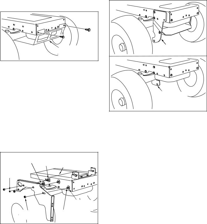
STEP 2: (SEE FIGURE 3)
•Fasten the R.H. Side Plate (bend facing out) to the front three holes in the tractor frame using three 3/8" x 1" carriage bolts (H), three large 1/2" washers (N) (see note) and three 3/8" nylock nuts (M). For the rear hole, use a 5/16" x 1" carriage bolt (F), a large 1/2" washer (N) and a 5/16" nylock nut (L). Place the washers between the tractor frame and the side plate. Tighten all bolts. Repeat for L.H. side plate.
NOTE: If there is an engine mounting plate (shown with dotted lines) leave the large 1/2" washer (N) off the bolt that goes through the plate.
•Reinstall the browning shield removed in figure 2.
•Go to page 8 "INSTRUCTIONS FOR 917 MODEL TRACTORS".
5/16" x 1" CARRIAGE |
ENGINE |
BOLT (F) |
MOUNTING |
(SEE NOTE) |
PLATE |
|
|
5/16" NYLOCK |
|
NUT (L) |
|
|
1/2" LARGE |
|
WASHER (N) |
3/8" NYLOCK |
3/8" x 1" CARRIAGE |
NUT (M) |
BOLT (H) |
FIGURE 3
INSTRUCTIONS FORTRACTORS WITH DUAL FRONT DECK SUSPENSION BRACKETS
IDENTIFY YOUR SUSPENSION BRACKETS
•Compare your tractor to the ones shown in figure 4.
•If your tractor resembles the top illustration, go to page 7 "INSTRUCTIONS FOR TYPE A TRACTORS".
•If your tractor resembles the bottom illustration, go to page 7 "INSTRUCTIONS FOR TYPE B TRACTORS".
TYPE A |
FRONT SUSPENSION |
BRACKET |
TYPE B |
FRONT SUSPENSION |
BRACKET |
FIGURE 4
6
 Loading...