

Operator’s Manual
32cc/1.9 cu.in. 2-Cycle
GASOLINE BRUSHWACKER®
DANGER:
Read and follow all Safety Rules and Operating
A
9
Instructions before first use of this product.
For answers to your questions about this product:
Call 7 am-7 pm, Mon.-Sat., or 10 am-7 pm, Sun.
1 -800-235-5878 (Hours listed are Central Time)
Sears, Roebuck and Co., Hoffman Estates, IL 60179 U.S.A.
530164363 9/12/06

TABLE OF CONTENTS
Warranty Statement 2 Storage 16
Safety Rules 2 Troubleshooting Table 17
Assembly 5 Emissions Statement 18
Operation 9 Parts List 20
Maintenance 13 Spanish 22
Service & Adjustments 15 Parts and Ordering Back Cover
WARRANTY STATEMENT
TWO YEAR FULL WARRANTY ON CRAFTSMAN® GAS BRUSHWACKER®
When used and maintained according to the operator's manual, if this product fails
due to a defect in material or workmanship within two years from the date of pur
chase, return it to any Sears store, Sears Service Center, or other Craftsman outlet in
the United States for free repair (or replacement if repair proves impossible).
This warranty excludes cutting line, blade, spark plug and air filter, which are ex
pendable parts that can wear out from normal use in less than one year.
This warranty applies for only 30 days from purchase date if this product is used
for commercial or rental purposes.
This warranty gives you specific legal rights, and you may also have other rights
which vary from state to state.
Sears, Roebuck and Co., Hoffman Estates, IL 60179
SAFETY RULES
a WARNING: When using gar
dening appliances, basic safety pre
cautions must always be followed to
reduce the risk of fire and serious
injury.
A DANGER: This power tool can
be dangerous! This unit can cause se
rious injury including amputation or
blindness to the operator and others.
The warnings and safety instructions
in this manual must be followed to pro
vide reasonable safety and efficiency
in using the unit. The operator is re
sponsible for following the warnings
and instructions in this manual and on
the unit. Read the entire operator’s
manual before assembling and using
the unit! Restrict the use of this unit to
persons who read, understand, and
follow the warnings and instructions in
this manual and on the unit. Never al
low children to operate this unit.
INSTRUCTION
MANUAL
MM DANGER: Blade can thrust vio
lently away from material it does not
SAFETY INFORMATION
ON THE UNIT
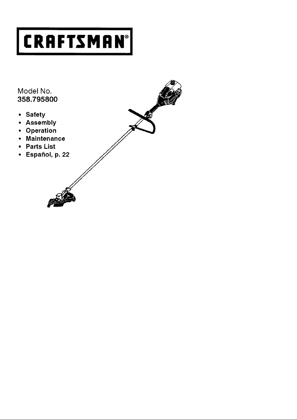
cut. Blade thrust can cause amputa
tion of arms or legs. Keep people and
animals 50 feet (15 meters) away.
^WARNING: Trimmer line can
throw objects violently. You and others
can be blinded or injured. Wear safety
glasses and leg protection.
ALWAYS WEAR:
p g Leg Guards
^WARNING: Hazard zone for
thrown objects. Blade/Trimmer line
Eye^^
Protection
Boots
Always use;
• Hearing protection
• Eye protection
• Head protection
Thrown
Objects
S!
can throw objects violently. Others can
be blinded or injured. Keep people
and animals 50 feet (15 meters) away.
mm WAR NIN G: Do not usg trim mer
head as a fastening device for the
blade.
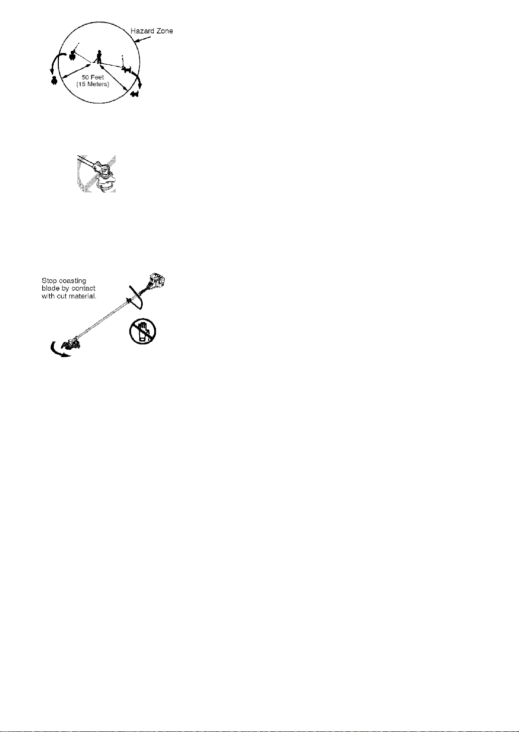
^WARNING; The blade continues
to spin after the throttle is released or,
engine is turned off. The coasting blade
can throw objects or seriously cut if ac
cidentally touched. Stop the blade by
contacting the right hand side of the
coasting blade with material already cut.
OPERATOR SAFETY
• Dress properly. Always wear safety
glasses or similar eye protection when
operating, or performing maintenance
on your unit. (Safety glasses are
available.) Eye protection should be
marked Z87.
• Always wear face or dust mask if op
eration is dusty.
• Aiways wear heavy, long pants, long
sleeves, boots, and gloves. Wearing
safety ieg guards is recommended.
• Always wear foot protection. Do not
go barefoot or wear sandals.
• Secure hair above shoulder length.
Secure or remove loose clothing and
jewelry or clothing with loosely hang
ing ties, straps, tassels, etc. They can
be caught in moving parts.
• Being fully covered also helps protect
you from debris and pieces of toxic
plants thrown by spinning line/blade.
• Stay Alert. Do not operate unit when
you are tired, ill, upset or under influ
ence of alcohol, drugs, or medication.
Watch what you are doing; use com
mon sense.
• Wear hearing protection.
• Never start or run the engine inside
a closed room or building. Breathing
exhaust fumes can kill,
• Keep handles free of oil and fuel,
• Always use the handlebar and a
properly adjusted shoulder strap
with a blade (see ASSEMBLY).
UNIT/MAINTENANCE SAFETY
^WARNING: Stop unit and dis
connect the spark plug before per
forming maintenance (except carbure
tor adjustments).
• Look for and replace damaged or
loose parts before each use. Look
for and repair fuel leaks before use.
Keep unit in good working condition.
• Throw away blades that are bent,
warped, cracked, broken, or dam
aged in any other way. Replace trim
mer head parts that are cracked,
chipped, broken, or damaged in any
other way before using the unit.
• Maintain unit according to recom
mended procedures. Keep blade
sharp. Keep cutting line at the prop
er length. ^
• Use only Craftsman®' brand replace
ment line. Never use wire, rope,
string, etc.
• Install required shield properly before
using the unit. Use the metal shield
for all metal blade use. Use the plastic
shield for all line trimmer use.
• Use only specified blade or trimmer
head; make sure it is properly in
stalled and securely fastened.

• NGVGr Start GnginG with clutch
shroud rGmoved. The dutch can fly
off and cause SGrious injury.
• Be sure blade or trimmer head stops
turning when engine idles.
• Make carburetor adjustments with
the lower end supported to prevent
blade or trimmer line from contacting
any object. Hold unit by hand; do not
use the shoulder strap for support.
• Keep others away when making car
buretor adjustments. _
• Use only recommended Craftsman'"'
accessories and replacement parts.
• Have all maintenance and service not
explained in this manual performed by
your Sears Service Center.
FUEL SAFETY
• Mix and pour fuel outdoors.
• Keep away from sparks or flames.
• Use a container approved for fuel.
• Do not smoke or allow smoking near
fuel or the unit or while using the unit.
• Avoid spilling fuel or oil. Wipe up all
fuel spills before starting engine.
• Move at least 10 feet {3 meters)
away from fueling site before start
ing engine.
• Stop engine and allow it to cool be
fore removing fuel cap.
• Empty the fuel tank before storing or
transporting the unit. Use up fuel left
in the carburetor by starting the en
gine and letting it run until it stops.
• Store unit and fuel in area where fue!
vapors cannot reach sparks or open
flames from water heaters, electric
motors or switches, furnaces, etc.
• Always store gasoline in a container
approved for flammable liquids.
CUTTING SAFETY
^WARNING; Inspect the area to
be cut before each use. Remove ob
jects (rocks, broken glass, nails, wire,
string, etc.) which can be thrown or
become entangled in the blade or
trimmer head.
• Keep others including children, ani
mals, bystanders, and helpers at least
50 feet (15 meters) away. Stop engine
immediately if you are approached.
• Always keep engine on the righthand side of your body.
• Hold the unit firmly with both hands.
• Keep firm footing and balance. Do
not overreach.
• Keep blade or trimmer head below
waist level. Do not raise engine
above your waist.
• Keep all parts of your body away
from blade, trimmer head, and muf
fler when engine is running. A hot
muffler can cause serious burns.
• Cut from your left to your right.
Cutting on right side of the shield will
throw debris away from the operator.
• Use only in daylight or good artificial
light.
• Use only for jobs explained in this
manual.
TRANSPORTING AND STORAGE
• Stop the unit before carrying.
• Keep muffler away from your body.
• Allow the engine to cool and secure
the unit before storing or transport
ing it in a vehicle.
• Empty the fuel tank before storing or
transporting the unit. Use up fuel left
in the carburetor by starting the en
gine and letting it run until it stops.
• Store unit so the blade or line limiter
blade cannot accidentally cause in
jury. The unit can be hung by the
shaft.
• Store unit out of reach of children.
This unit is not equipped with an anti
vibration system and is intended for
occasional use only.
SAFETY NOTICE: Exposure to vibra
tions through prolonged use of gasoline
powered hand tools could cause blood
vessel or nerve damage in the fingers,
hands, and joints of people prone to cir
culation disorders or abnormal swell
ings. Prolonged use in cold weather
has been linted to blood vessel dam
age in otherwise healthy people. If
symptoms occur such as numbness,
pain, loss of strength, change in skin
color or texture, or loss of feeling in the
fingers, hands, or joints, discontinue the
use of this tool and seek medical atten
tion. An anti-vibration system does not
guarantee the avoidance of these prob
lems. Users who operate power tools
on a continual and regular basis must
monitor closely their physical condition
and the condition of this tool.
SPECIAL NCTiCE: This unit is
equipped with a temperature limiting
muffler and spark arresting screen
which meets the requirements of Cali
fornia Codes 4442 and 4443. All U.S.
forest land and the states of California,
Idaho, Maine, Minnesota, New Jersey,
Oregon, and Washington require by law
that many internal combustion engines
be equipped with a spark arresting
screen. If you operate in a locale where
such regulations exist, you are legally
responsible for maintaining the operat
ing condition of these parts. Failure to
do so is a violation of the law. For nor
mal homeowner use, the muffler and
spark arresting screen will not require
ASSEMBLY
CARTON CONTENTS
Check carton contents against the fol
lowing list.
Model 358.795800
• Brushcutter
• Cupped washer
• Large nut for installing blades
• Hex wrench
• Handlebar
• Bracket cover
• Bracket cover screws (2)
• Metal blade shield
• Blade shield screws (4)
• 4-Point weed blade
• 8-Point weed blade
• Plastic shield
• Wing nut (screwed onto shield)
• Trimmer head (assembled on unit)
• Shoulder strap with warning
• Container of line
• Container of oil
Examine parts for damage. Do not
use damaged parts.
NOTE: If you need assistance or find
parts missing or damaged, call
1-800-235-5878.
It is normal for the fuel filter to rattle in
the empty fuel tank.
Finding fuel or oil residue on muffler is
normal due to carburetor adjustments
and testing done by the manufacturer.
ASSEMBLY
^WARNING: Always stop unit
and disconnect spark plug before per
forming any assembly procedures.
^ WARNING: if received as
sembled, repeat all steps to ensure
your unit is properly assembled and all
fasteners are secure.
TOOLS REQUIRED
• Hex Wrench (provided)
• Adjustable Wrench
• Phillips Screwdriver
ATTACHING THE HANDLEBAR
A DANGER: To avoid serious inju
ry, the barrier portion of the handlebar
must be installed as shown to provide a
barrier between operator and the spin
any service. After 50 hours of use, we
recommend that your muffler be ser
viced or replaced by your Sears Service
Center.
ning blade.
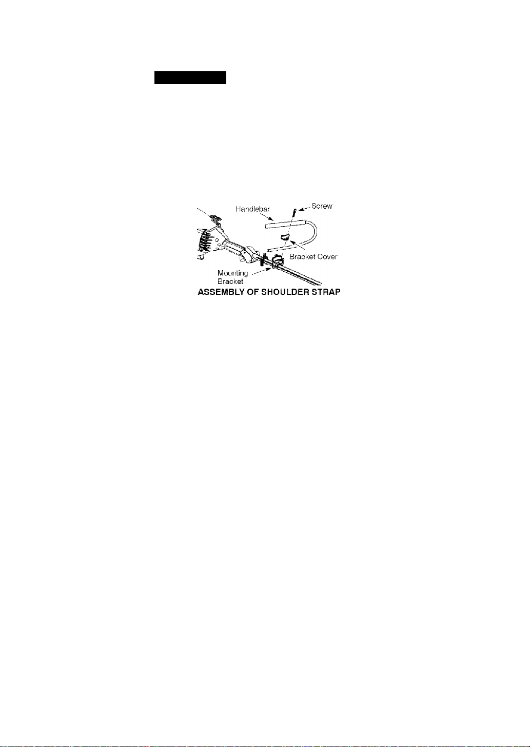
1. Locate the decal on the handlebar.
This decal includes an arrow. Posi
tion the handlebar with the mount
ing bracket at the end of the arrow.
2. Position the bracket cover over the
handlebar. Again make sure the
handlebar is at the end of the arrow.
3. insert screws and hand tighten
only. Be sure the handlebar is
installed correctly; then, tighten
each screw securely with the hex
wrench.
liWARNING: Proper shoulder
strap and handlebar adjustments must
be made with the engine completely
stopped before using unit.
1. Insert your right arm and head
through the shoulder strap and al
low it to rest on your left shoulder.
Make sure the danger sign is on
your back and the hook is to the
right side of your waist.
NOTE: A one-half twist is built in the
shoulder strap to allow the strap to rest
flat on the shoulder.
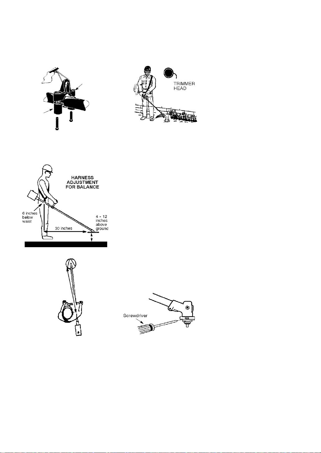
2. Adjust the strap, allowing the hook
to be about 6 inches below the
waist.
3. Fasten the strap hook to the clamp
located between the trigger handle
and the handlebar clamp base and
lift the tool to the operating position.
4. Try on shoulder strap and adjust
for fit and balance before starting
the engine or beginning a cutting
operation.
NOTE: It may be necessary to relo
cate the shoulder strap clamp on the
shaft for proper balancing of unit.
TO RELOCATE SHOULDER STRAP
CLAMP:
1. Loosen and remove both clamp
screws.
2. Place the upper shoulder strap
clamp over the shaft.
3. Position the lower shoulder strap
clamp under the shaft and align
the upper and lower clamp screw
holes.
Upper Shoulder
Strap Clamp
Lower Shoulder
Strap Clamp
Screws
4. Insert two screws into the screw
holes.
5. Secure shoulder strap clamp by
tightening screws with a hex
wrench.
30 inches
CONFIGURING YOUR UNIT
You can configure your unit using a cut
ting head for grass and light weeds, or
a weed blade for cutting grass, weeds,
and brush up to 1/2 inch In diameter. To
assemble your unit, go to the section for
the desired configuration and follow the
instructions.
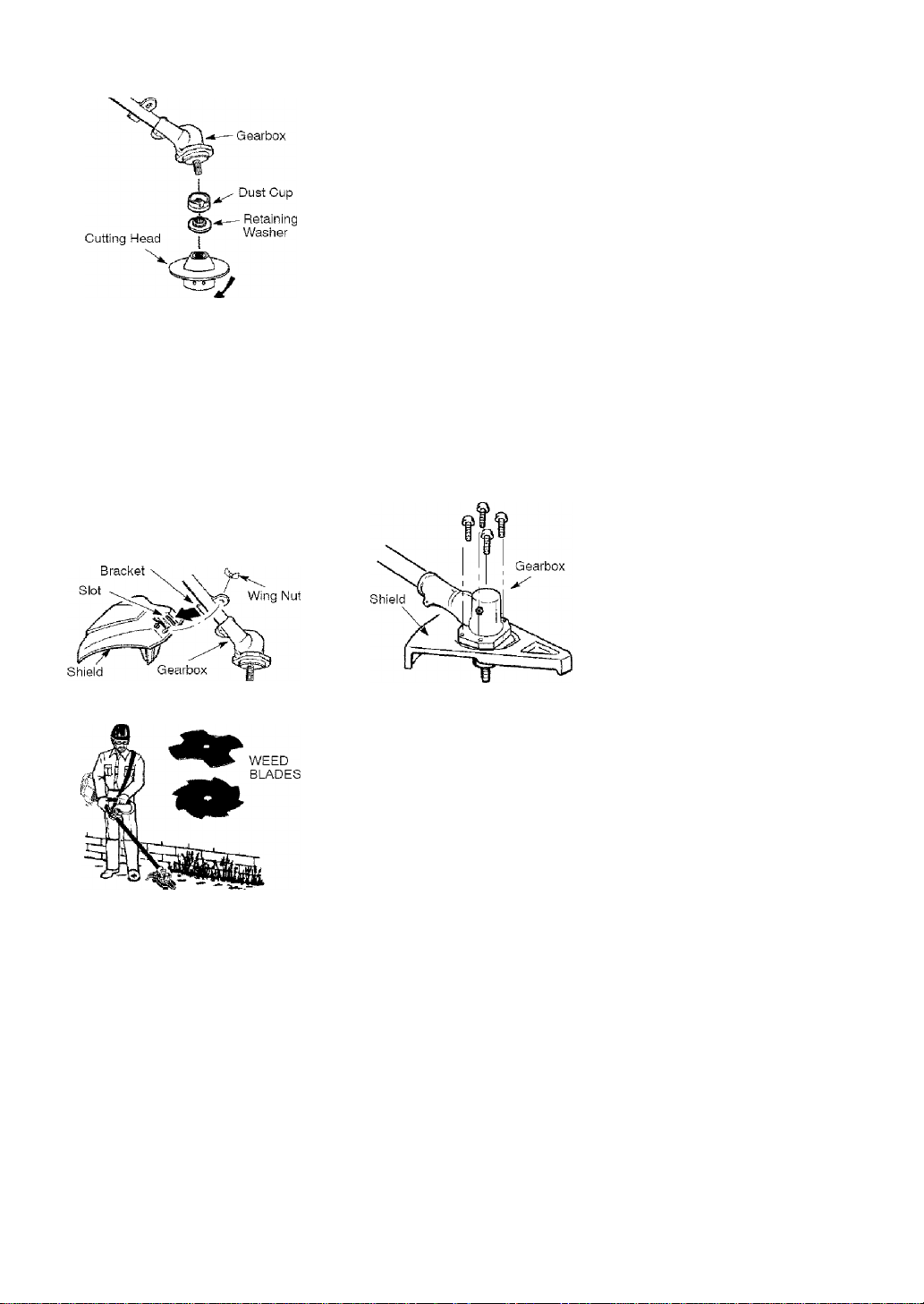
ASSEMBLY INFORMATION TRIMMER HEAD
NOTE: Remove the blade and metal
shield before attaching the plastic shield
and trimmer head. To remove blade,
align hole in the dust cup with the hole
in the side of the gearbox by rotating
the dust cup. Insert a small screwdriv
er into aligned holes. This will keep the
shaft from turning while loosening the
blade nut. Remove blade nut by turning
clockwise. Remove the screwdriver.
Remove both washers and blade. To
remove metal shield, loosen and re
move the four mounting screws. See
ATTACHING THE METAL SHIELD and
INSTALLATION OF THE METAL BLADE for
illustrations. Be sure to store ali parts
and instructions for future use.
INSTALLATION OF THE CUTTING
HEAD (if not already installed)
NOTE: Before installing the trimmer
head, make sure the dust cup and re
taining washer are positioned on the
shaft of the gearbox. The retaining
washer must be positioned with the
raised section toward the gearbox.
1. Align hole in the dust cup with the
hole in the side of the gearbox by
rotating the dust cup.
2. Insert a small screwdriver into
aligned holes. This will keep the
shaft from turning while tightening
trimmer head.
While holding the screwdriver in
position, thread trimmer head onto
the shaft by turning counterclock
wise. Only tighten hand tight!
4. Remove the screwdriver.
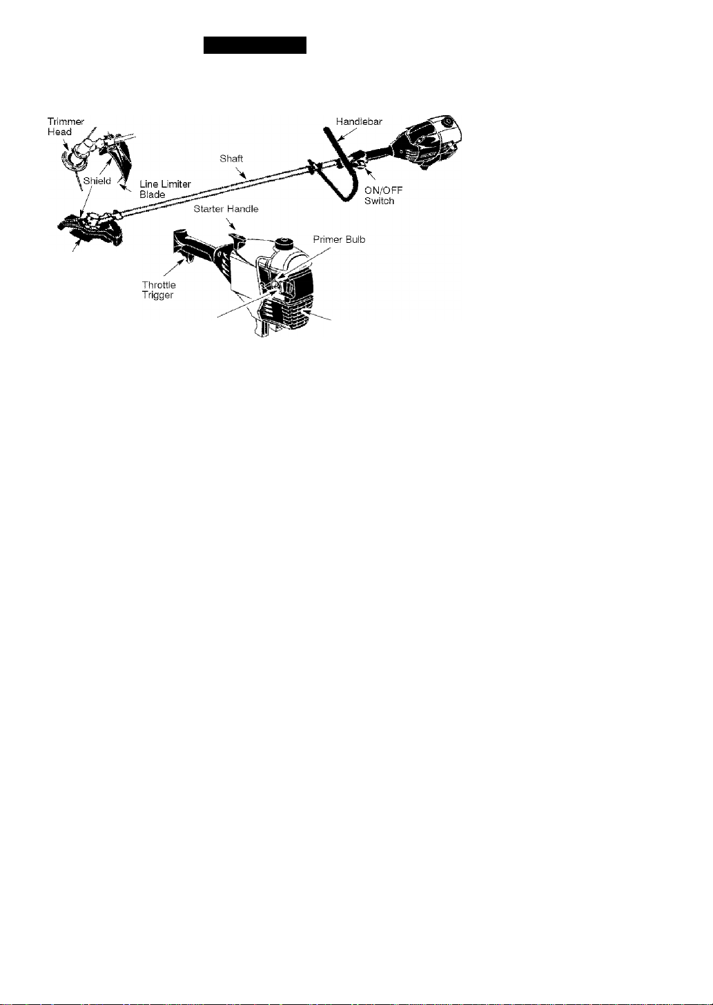
ATTACHING THE PLASTIC SHIELD
A WARNING: The shield must be
properly installed. The shield provides
partial protection from the risk of
thrown objects to the operator and
others and is equipped with a line lim
iter blade which cuts excess line to the
proper length. The line limiter blade
(on underside of shield) is sharp and
can cut you.
1. Remove wing nut from shield.
2. insert bracket into slot on shield.
3. Pivot shield until bolt passes
through hole in bracket.
4. Tighten the wing nut securely.
in the side of the gearbox by rotating
the dust cup. Insert a small screwdriver
into aligned holes. This will keep the
shaft from turning while loosening the
trimmer head. Remove the trimmer
head by turning clockwise. Remove the
screwdriver. To remove the plastic
shield, loosen and remove wing nut.
Pivot shield to release bracket from slot.
See INSTALLATION OF THE CUTTING
HEAD and ATTACHING THE PLASTIC
SHIELD for illustrations. Be sure to store
all parts and instructions for future use.
Never use the trimmer head with the
metal blade installed.
ATTACHING THE METAL SHIELD
^WARNING: The metal shield
must be properly installed on the tool
anytime the too! is used with a blade.
The forward tip of the metal shield
helps to reduce the occurrence of
blade thrust which can cause serious
injury such as amputation to the oper
ator or bystanders. Failure to install
the shield in the position shown can
result in serious injury to the operator.
The length of the shield must be
aligned with the length of the shaft.
1. Place the metal shield under the
gearbox, and align the screw holes.
ASSEMBLY INFORMATION - WEED
BLADES
NOTE: Remove the trimmer head and
plastic shield before attaching the metal
shield and installing one of the weed
blades. To remove the trimmer head,
align hole in the dust cup with the hole
2. Insert and thread the 4 mounting
screws through the holes of the
gearbox and the metal shield.
Tighten evenly and securely with
the hex wrench provided,
INSTALLATION OF THE METAL
BLADE
^ WARN IN G: Wear protective
gloves when handling or performing
maintenance on the blade to avoid inju
ry. The blade is sharp and can cut you
even when it is not moving,
A WARNING : Do not use any
blades, or fastening hardware other
than the washers and nuts shown in the
following illustrations. These parts must
be provided by Sears, and installed as

shown below. Failure to use proper
parts can cause the blade to fly off and
seriously hurt you or others.
NOTE: The dust cup and retaining
washer are located on the gearbox
shaft and not in the parts bag. All other
fasteners mentioned in the following as
sembly steps are in the parts bag.
1. Remove the retaining washer from
the threaded shaft of the gearbox.
Leave the dust cup on the shaft,
2. install the blade and the retaining
washer over the threaded shaft.
3. Make sure the raised part of the
retaining washer is facing the
gearbox and the raised area fits
into the hole in the center of the
biade.
4. Slide the blade and retaining wash
er onto the shaft of the gearbox.
NOTE; When installing 8-point
weed blade, ensure side of blade
with decal is facing gearbox and
points of blade will rotate counter
clockwise (see illustration).
8-POINTBLADE
DECAL SIDE OF
BLADE MUST
FACE GEARBOX
Place the cupped washer onto the
shaft. Make sure the cupped side
of the washer is toward the biade,
install the blade nut by threading
onto the shaft counterclockwise.
NOTE: Make sure all parts are in piace
as illustrated, and the blade is sand
wiched between the dust cup and the
retaining washer. There should be no
space between the blade and the dust
cup or the retaining washer.
7. Aiign hole in dust cup with hole in
side of gearbox by rotating the
blade.
8. insert a small screwdriver into
aligned holes. This will keep the
shaft from turning while tightening
the blade nut.
9,
Tighten blade nut firmly with a
wrench while holding screwdriver in
position.
10.
Remove the screwdriver.
11.
Turn blade by hand. If the blade
binds against the shield, or appears
to be uneven, the blade is not cen
tered, and you must reinstali,
NOTE: To remove blade, insert screw
driver into aligned holes. Unthread the
nut and remove parts. Be sure to store
parts and instructions for future use.
OPERATION
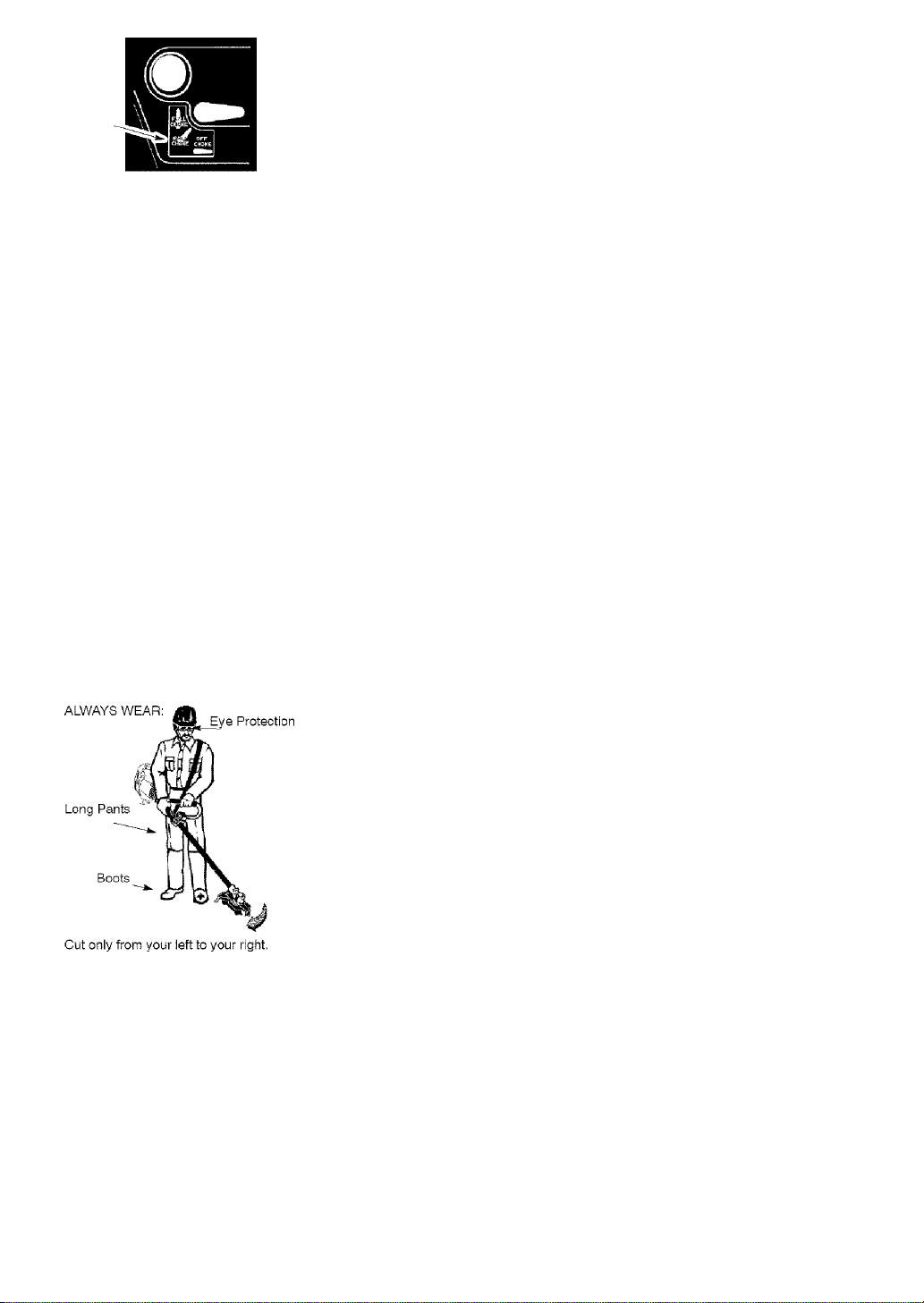
KNOW YOUR BRUSHWACKER
READ THIS OPERATOR’S MANUAL AND SAFETY RULES BEFORE OPERATING YOUR
UNIT. Compare the illustrations with your unit to familiarize yourself with the location of
the various controls and adjustments. Save this manual for future reference.
Blade
Choke Lever
ON/OFF SWITCH
The ON/OFF SWITCH is used to stop the
engine. Move the switch to the OFF
position to stop the engine.
PRIMER BULB
The PRIMER BULB removes air from
the carburetor and fuel lines and fills
them with fuel. This allows you to start
the engine with fewer pulls on the
starter rope. Activate the primer bulb
by pressing it and allowing it to return
to its original form.
BEFORE STARTING ENGINE
ik WARNING; Be sure to read
the fuel information in the safety rules
before you begin. If you do not under
stand the safety rules, do not attempt
to fuel your unit. Call 1 -800-235-5878.
FUELING ENGINE
A WARNING: Remove fuel cap
slowly when refueling.
This engine is certified to operate on
unleaded gasoline. Before operation,
gasoline must be mixed with a good
quality synthetic 2-cycle air-cooled en
gine oil. We recommend Craftsman
brand synthetic oil. Mix gasoline and
oil at a ratio of 40:1, A 40:1 ratio is ob
tained by mixing 3.2 ounces of oil with
1 gallon of unleaded gasoline. In
cluded with this brushcutter is a 3.2
ounce container of oil. Pour the entire
Muffler
CHOKE
The CHOKE helps to supply fuel to the
engine to aid in cold starting. Activate
the choke by moving the choke lever to
the FULL CHOKE position. After the en
gine attempts to start, move the choke
lever to the HALF CHOKE position. Once
engine has started, move the choke le
ver to the OFF CHOKE position.
contents of this container into 1 gallon
of gasoline to achieve the proper fuel
mixture. DO NOT USE automotive oil or
marine oil. These oils will cause en
gine damage. When mixing fuel, fol
low instructions printed on container.
Once oil is added to gasoline, shake
container momentarily to assure that the
fuel is thoroughly mixed. Always read
and follow the safety rules relating to
fuel before fueling your unit.
IMPORTANT
Experience indicates that alcohol
blended fuels (called gasohol or using
ethanol or methanol) can attract mois
ture which leads to separation and
formation of acids during storage.
Acidic gas can damage the fuel sys
tem of an engine while in storage.
To avoid engine problems, empty the
fuel system before storage for 30 days

or longer. Drain the gas tank, start the
engine and let it run until the fuel lines
and carburetor are empty. Use fresh
fuel next season.
Never use engine or carburetor clean
er products in the fuel tank or perma
nent damage may occur.
See the STORAGE section for addition
al information.
HOW TO STOP YOUR UNIT
• To stop the engine, move the ON/
OFF switch to the off position.
• if engine does not stop, move choke
lever to FULL CHOKE position.
Throttle Trigger
HOW TO START YOUR UNIT
WARNING; The trimmer head
will turn while starting the engine.
Avoid any contact with the muffler. A
hot muffler can cause serious burns.
STARTING A COLD ENGINE (or a
warm engine after running out of
fuel)
.§1 <№
,e-iitjA' Ll Starting Position
Starter Handle
Primer Bulb
Muffler
1. Set unit on a flat surface.
2. Move ON/OFF switch to the ON
position.
3. Slowly press the primer bulb 6
times,
4. Move choke lever to FULL CHOKE
by aligning lever with position
shown on decal {see following
illustration).
Choke
position
decal
Squeeze the throttle trigger ftjlly and
hold through all remaining steps.
Pull starter rope handle sharply
until engine sounds as if it is trying
to start, but do not pull rope more
than 6 times.
As soon as engine sounds as if it
is trying to start, move choke lever
to HALF CHOKE by aligning lever
with position shown on decal (see
illustration below).
Choke
position
decal
________
Pull starter rope sharply until engine
runs, but no more than 6 pulls. If the
engine doesn’t start after 6 pulls (at
the HALF CHOKE position), move the
choke lever to the FULL CHOKE
position and press the primer bulb 6
times. Squeeze and hold the throttle
trigger and pull the starter rope 2
more times. Move the choke lever
to the HALF CHOKE position and pull
the starter rope until the engine
runs, but no more than 6 pulls. It the
engine doesn’t start, repeat proce
dure 2 additional times,
NOTE: If engine still doesn’t start, it
is probably flooded. Proceed to
STARTING A FLOODED ENGINE.
Once the engine starts, allow it to
run 10 seconds, then move the
choke lever to OFF CHOKE by align
ing lever with position shown on de
cal (see illustration below). Allow the
unit to run for 30 more seconds at
OFF CHOKE before releasing the
throttle trigger. NOTE: if engine dies
with the choke lever in the OFF
CHOKE position, move the choke le
ver to the HALF CHOKE position and
pull the rope until engine runs, but
no more than 6 pulls.
10
Choke
position
decal
STARTING A WARM ENGINE
1. Move ON/OFF switch to the ON
position.
2. Move the choke lever to the HALF
CHOKE position.
3. Squeeze and hold the throttle trig
ger. Keep throttle trigger fully
squeezed until the engine runs
smoothly.
4. Pull starter rope sharply until engine
runs, but no more than 5 pulls.
5. Allow engine to run 15 seconds,
then move the choke lever to the
OFF CHOKE position.
NOTE: If engine has not started, pull
starter rope 5 more pulls. If engine still
does not run, it is probably flooded.
STARTING A FLOODED ENGINE
Flooded engines can be started by
placing the choke lever in the OFF
CHOKE position; then, pull the rope to
clear the engine of excess fuel. This
could require pulling the starter handle
many times depending on how badly
the unit is flooded. If the unit still
doesn’t start, refer to TROUBLESHOOT
ING TABLE or call 1 -800-235-5878.
OPERATING INSTRUCTIONS
To maximize operating efficiency, do
not run the engine for longer than 1
minute at a time at full throttle.
OPERATING POSITION
When operating unit, clip shoulder
strap onto clamp, stand as shown and
check for the following:
• Wear hearing protection, eye protec
tion, head protection and heavy clo
thing.
• Extend your left arm and hold han
dlebar grip with your left hand.
• Field throttle grip with your right hand
with finger on throttle trigger.
• Keep unit below waist level.
• Keep shoulder strap pad centered
on your left shoulder and danger
sign centered on your back.
• Maintain full weight of tool on your
left shoulder.
• Cut only from your left to your right to
ensure debris is thrown away from
you. Without bending over, keep the
blade or trimmer head near and par
allel to the ground and not crowded
into material being cut.
OPERATING INSTRUCTIONS FOR
USE WITH TRIMMER HEAD
^WARNING: Always wear eye
protection. Never lean over the trimmer
head, flocks or debris can ricochet or
be thrown into eyes and face and
cause blindness or other serious injury.
Before trimming, bring engine to a
speed sufficient to cut material to be
trimmed.
Do not run the engine at a higher speed
than necessary. The cutting line will cut
efficiently when the engine is run at less
than full throttle. At lower speeds, there
is less engine noise and vibration. The
cutting line will last longer and will be
less likely to “weld” onto the spool.
Always release the throttle trigger and
allow the engine to return to idle
speed when not cutting.
To stop engine:
• Release the throttle trigger.
• Move ON/OFF switch to the OFF
position.
^WARNING: Use minimum
speed and do not crowd the line when
cutting around hard objects (rock,
gravel, fence posts, etc.), which can
damage the trimmer head, become
entangled in the line, or be thrown
causing a serious hazard.
• The tip of the line does the cutting.
You wiil achieve the best perform
ance and minimum line wear by not
crowding the line into the cutting
area. The right and wrong ways are
shown below.
11
Tip of line does the Line crowded into
• The line will easily remove grass
and weeds from around walls,
fences, trees and flower beds, but it
also can cut the tender bark of trees
or shrubs and scar fences.
• For trimming or scalping, use less
than full throttle to increase line life
and decrease head wear, especially:
• During light duty cutting.
• Near objects around which the line
can wrap such as small posts,
trees or fence wire.
• For mowing or sweeping, use full
throttle for a good clean job.
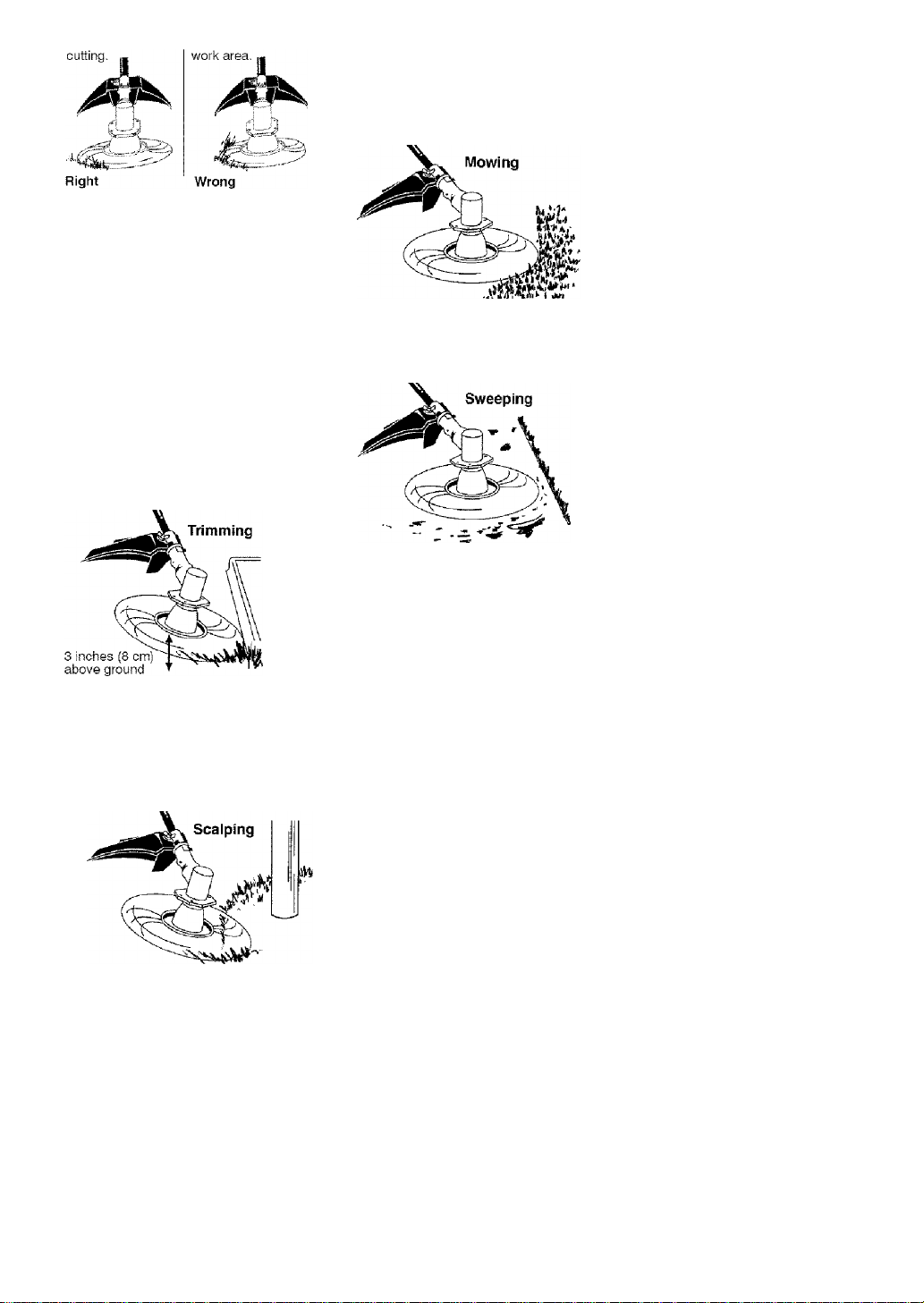
TRIMMING - Hold the bottom of the
trimmer head about 3 inches {8 cm)
above the ground and at an angle. Al
low only the tip of the line to make
contact with vegetation. Do not force
trimmer line into work area.
SCALPING - The scalping technique
removes unwanted vegetation down to
the ground. Hold the bottom of the trim
mer head about 3 inches (8 cm) above
the ground and at an angle. Allow the
tip of the line to strike the ground
around trees, posts, monuments, etc.
This technique increases line wear.
MOWING - Your trimmer is ideal for
mowing in places conventional lawn
mowers cannot reach. In the mowing
position, keep the iine parallel to the
ground. Avoid pressing the head into
the ground as this can scalp the
ground and damage the tool.
SWEEPING - The fanning action of the
rotating line can be used to blow away
loose debris from an area. Keep the line
parallel to and above the area surface
and swing the tool from side to side.
OPERATING INSTRUCTIONS FOR
USE WITH WEED BLADES
• Blade Thrust is a reaction that only
occurs when using a bladed unit. This
reaction can cause serious injury
such as amputation. Carefully study
this section. It is important that you
understand what causes blade thrust,
how you can reduce the chance of its
occurring, and how you can remain in
control of unit if blade thrust occurs.
• WHAT CAUSES BLADE THRUST -
Blade Thrust can occur when the
spinning blade contacts an object that
it does not cut. This contact causes
the blade to stop for an instant and
then suddenly move or “thrust” away
from the object that was hit. The
“thrusting” reaction can be violent
enough to cause the operator to be
propelled in any direction and lose
control of the unit. The uncontrolled
unit can cause serious injury if the
blade contacts the operator or others.
• WHEN BLADE THRUST OCCURS
- Blade Thrust can occur without
warning if the blade snags, stalls, or
binds. This is more likely to occur in
12

areas where it is difficult to see the
material being cut. By using the unit
properfy, the occurrence of blade
thrust will be reduced and the opera
tor will be less likely to lose control.
Cut only grass, weeds, and woody
brush up to 1/2 inch in diameter with
the weed blade. Do not let the blade
contact material it cannot cut such as
stumps, rocks, fences, metal, etc., or
clusters of hard, woody brush having
a diameter greater than 1/2 inch.
Keep the blade sharp. A dull blade
is more likely to snag and thrust.
Cut only at full throttle. The blade will
have maximum cutting power and is
less likely to bind or stall.
“Feed” the blade deliberately and
not too rapidly. The blade can thrust
away if it is fed too rapidly.
Cut only from your left to your right.
Cutting on right side of the shield will
throw debris away from the operator.
Use the shoulder strap and keep a
firm grip on the unit with both hands.
A properly adjusted shoulder strap
will support the weight of the unit,
freeing your arms and hands to con
trol and guide the cutting motion.
Keep feet comfortably spread apart
and braced for a possible sudden,
rapid thrust of unit. Do not overreach.
Keep firm footing and balance.
Keep blade below waist level; it will
be easier to maintain control of unit.
• Do not raise the engine above your
waist as the blade can come dan
gerously close to your body.
• Do not swing unit with such force
that you are in danger of losing your
balance.
Bring the engine to cutting speed be
fore entering the material to be cut.If
the blade does not turn when you
squeeze the throttle trigger, make sure
shaft is fully inserted into the engine.
Always release the throttle trigger and
allow engine to return to idle speed
when not cutting. The blade should
not turn while the engine is running at
idle. If the blade turns at idle, do not
use your unit. Refer to the
TOR ADJUSTMENT section or contact
your Sears Service Center,
• Maintain good firm footing while using
the unit. Do this by planting feet firmly
in a comfortable apart position.
• Cut while swinging the upper part of
your body from left to right.
• As you move forward to the next
area to cut, be sure to maintain your
balance and footing.
RECOMMENDED CUTTING POSITION
Cut using the 2 ■
o'clock to 4 o'clock
position of the
blade
Ci WARNING: The operator or oth
ers must not try to clear away cut mate
rial with the engine running or the blade
turning to avoid serious injury. Stop en
gine and blade before removing materi
als wrapped around blade or shaft.
CARBURE
2 o’clock
I't
4 o'clock
MAINTENANCE
MAINTENANCE SCHEDULE
A
WARNING: Disconnect the spark plug before performing maintenance
except for carburetor adjustments.
CARE & MAINTENANCE TASK WHEN TO PERFORM
Check for loose fasteners and parts Before each use
Check for damaged or worn parts Before each use
Inspect and clean unit and decals After each use
Clean air filter Every 5 hours of operation
Inspect muffler and spark arresting screen Every 50 hours of operation
Replace spark plug Yearly
13

GENERALRECOMMENDATIONS
The warranty on this unit does not
cover items that have been subjected
to operator abuse or negligence. To
receive full value from the warranty,
the operator must maintain unit as
instructed in this manual. Various ad
justments wiil need to be made peri
odically to properly maintain your unit.
CHECK FOR LOOSE
FASTENERS AND PARTS
• Spark Plug Boot
• Air Filter
• Housing Screws
• Assist Handle Screw
• Debris Shield
CHECK FOR DAMAGED OR
WORN PARTS
Contact Sears Service Center for re
placement of damaged or worn parts.
• ON/OFF Switch - Ensure ON/OFF
switch functions properly by moving
the switch to the OFF position. Make
sure engine stops; then restart en
gine and continue.
• Fuel Tank - Discontinue use of unit
if fuel tank shows signs of damage
or leaks.
• Debris Shield - Discontinue use of
unit if debris shield is damaged.
INSPECT AND CLEAN UNIT AND
DECALS
• After each use, inspect complete
unit for loose or damaged parts.
Clean the unit and decals using a
damp cloth with a mild detergent.
• Wipe off unit with a clean dry cloth.
CLEAN AIR FILTER
A dirty air filter decreases engine per
formance and increases fuel con
sumption and harmful emissions. Al
ways clean after every 5 hours of
operation.
1. Clean the cover and the area
around it to keep dirt from falling
into the carburetor chamber when
the cover is removed.
2. Remove parts by pressing button
to release air filter cover.
NOTE: To avoid creating a fire hazard
or producing harmful evaporative
emissions, do not clean filter in gaso
line or other flammable solvent.
3. Wash the filter in soap and water.
4. Allow filter to dry.
5. Replace parts.
INSPECT MUFFLER AND SPARK
ARRESTING SCREEN
^WARNING: The muffler on this
product contains chemicals known to
the State of California to cause cancer.
As your unit is used, carbon deposits
build up on the muffler and spark ar
resting screen.
For normal homeowner use, however,
the muffler and spark arresting screen
will not require any service. After 50
hours of use, we recommend that your
muffler be serviced or replaced by your
Sears Service Center.
REPLACE SPARK PLUG
Replace the spark plug each year to
ensure the engine starts easier and
runs better. Set spark plug gap at
0. 025.inch, ignition timing is fixed and
nonadjustable.
1. Twist, then pull off spark plug boot.
2. Remove spark plug from cylinder
and discard.
3. Replace with Champion RCJ-6Y
spark plug and tighten securely
with a 3/4 inch socket wrench.
4. Reinstall the spark plug boot.
14

SERVICE AND ADJUSTMENTS
LINE REPLACEMENT
• Always use Craftsman replacement
line.
Choose the line size best suited for
the job at hand. Red line is designed
for cutting grass and small weeds.
The black colored line is designed for
cutting larger weeds and light brush.
NOTE: Before inserting new line into
the holes in the cutting head, identify
the proper holes. Follow directions as
shown on the line glide plate.
1. Remove the old line and line glide
plate from the cutting head.
2. Clean entire surface of cutting head.
3. Reinstall line glide plate (see il
lustration). Align arrow with:
when using medium (red) or
©
large (black) line
when using lines with diameter
(§) smaller than medium (red) line
(optional)
Arrow
/
Cutting head
NOTE: Line glide plate must be rein
stalled in cutting head before inserting
new line.
4. insert both ends of your line
through the proper holes in the
side of the cutting head.
Pull the line and make sure the
line is against the hub and ex
tended full through the positioning
tunnels.
6. Correctly installed line will be the
same length on both ends
Line against
the hub
BLADE REPLACEMENT
Refer to the ASSEMBLY section for
blade replacement instructions and
illustrations.
CARBURETOR ADJUSTMENT
^WARNING: Keep others away
when making idle speed adjustments.
The trimmer head or blade will be
spinning during most of this proce
dure. Wear your protective equipment
and observe all safety precautions.
After making adjustments, the trimmer
head or blade must not move/spin at
idle speed.
The carburetor has been carefully set
at the factory. Adjustments may be
necessary if you notice any of the fol
lowing conditions:
• Engine will not idle when the throttle is
released.
• The trimmer head or blade moves/
spins at idle.
Make adjustments with the unit sup
ported so the cutting attachment is off
the ground and will not make contact
with any object. Hold the unit by hand
while running and making adjust
ments. Keep all parts of your body
away from the cutting attachment and
muffler.
Idle Speed Adjustment
Allow engine to idle. Adjust speed until
engine runs without trimmer head or
blade moving or spinning (idle too
fast) or engine stalling (idle speed too
slow).
• Turn idle speed screw clockwise to
increase engine speed if engine
stalls or dies.
• Turn idle speed screw counterclock
wise to decrease engine speed if
trimmer head or blade moves or
spins at idle.
15

a WARNING: Recheck the idle
speed after each adjustment. The
trimmer head or blade must not move
or spin at idle speed to avoid serious
injury to the operator or others.
Idle Speed
Screw
STORAGE
a WARNING: Perform the follow
ing steps after each use:
• Allow engine to cool before storing
or transporting.
• Store unit and fuel in a well venti
lated area where fuel vapors cannot
reach sparks or open flames from
water heaters, electric motors or
switches, furnaces, etc.
• Store unit with all guards in place.
Position unit so that any sharp ob
ject cannot accidentally cause injury.
• Store unit and fuel well out of the
reach of children.
SEASONAL STORAGE
Prepare unit for storage at end of sea
son or if it will not be used for 30 days
or more.
If your unit is to be stored for a period
of time:
• Clean the entire unit before lengthy
storage.
• Store in a clean dry area.
• Lightly oil external metal surfaces.
FUEL SYSTEM
Empty the fuel system before storage
for 30 days or longer. Drain the gas
tank, start the engine and let it run un
til the fuel lines and carburetor are
empty. Use fresh fuel next season.
Under FUELING ENGINE in the OPERA
TION section of this manual, see mes
sage labeled IMPORTANT regarding
the use of gasohol in your engine.
If you require further assistance or are
unsure about performing this proce
dure, contact your Sears Service Cen
ter or call our customer assistance
help line at 1 -800-235-5878.
Fuel stabilizer is an acceptable alter
native in minimizing the formation of
fuel gum deposits during storage. Add
stabilizer to the gasoline in the fuel
tank or fuel storage container. Follow
the mix instructions found on stabilizer
container. Run engine at least 5 min
utes after adding stabilizer.
Craftsman 40:1,2-cycle engine oil {air
cooled) is already blended with fuel
stabilizer. If you do not use this Sears
oil, you can add a fuel stabilizer to
your fuel tank.
ENGINE
• Remove spark plug and pour 1 tea
spoon of 40:1, 2-cycle engine oil (air
cooled) through the spark plug
opening. Slowly pul! the starter rope
8 to 10 times to distribute oil.
• Replace spark plug with new one of
recommended type and heat range.
• Clean air filter.
• Check entire unit for loose screws,
nuts, and bolts. Replace any dam
aged, broken, or worn parts.
• At the beginning of the next season,
use only fresh fuel having the proper
gasoline to oil ratio.
OTHER
• Do not store gasoline from one sea
son to another.
• Replace your gasoline can if it starts
to rust.
16

TROUBLESHOOTING TABLE
^WARNING: Always stop unit and disconnect spark plug before perform
ing all of the recommended remedies below except remedies that require
operation of the unit.
TROUBLE CAUSE REMEDY
Engine wilt not
start.
Engine wilt
not idle
properly.
Engine wilt not
accelerate,
lacks power,
or dies under
a load.
1. ON/OFF switch in
OFF position.
2. Engine flooded.
3. Fuel tank empty.
4. Spark plug not firing.
5. Fuel not reaching
carburetor.
e. Carburetor requires
adjustment.
1. Carburetor requires
adjustment.
2. Crankshaft seals worn.
3. Compression low.
1. Air filter dirty.
2. Spark plug fouled.
3. Carburetor requires
adjustment.
4. Carbon build-up on
muffler outlet screen.
5. Compression low.
1. Move ON/OFF switch to the ON
position.
2. See “Starting a Flooded Engine” in
Operation Section.
3. Fill tank with correct fuel mixture.
4. Install new spark plug.
5. Check for dirty fuel filter; replace.
Check for kinked or split fuel line;
repair or replace.
6. Contact Sears Service (see back cover).
1. See “Carburetor Adjustment” in
Service and Adjustments Section.
2. Contact Sears Service (see back cover).
3. Contact Sears Service (see back cover).
1. Clean or replace air filter.
2. Clean or replace plug and regap.
3. Contact Sears Service (see back cover).
4. Contact Sears Service (see back cover).
5. Contact Sears Service (see back cover).
Engine
smokes
excessively.
Engine runs
hot.
1. Choke partially on.
2. Fuel mixture incorrect.
3. Air filter dirty.
4. Carburetor requires
adjustment.
1. Fuel mixture incorrect.
2. Spark plug incorrect,
3, Carburetor requires
adjustment.
4, Carbon build-up on
muffler outlet screen.
1. Adjust choke.
2. Empty fuel tank and refill with
correct fuel mixture.
3. Clean or replace air filter.
4. Contact Sears Service (see back cover).
1. See “Fueling Engine” in Cperation
section.
2. Replace with correct spark plug.
3. Contact Sears Service (see back cover).
4. Contact Sears Service (see back cover).
17

U.S. EPA / CALIFORNIA
EMISSION CONTROL WARRANTY STATEMENT
YOUR WARRANTY RIGHTS AND OB
LIGATIONS: The U.S. Environmental
Protection Agency/Caiifornia Air Re
sources Board and Sears, Roebuck
and Co., U.S.A., are pleased to explain
the emissions control system warranty
on your year 2005 and later small off
road engine. In California, all small off
road engines must be designed, built,
and equipped to meet the State’s strin
gent anti-smog standards. Sears must
warrant the emission control system on
your small off-road engine for the peri
ods of time listed below provided there
has been no abuse, neglect, or improp
er maintenance of your small off-road
engine. Your emission control system
includes parts such as the carburetor
and the ignition system. Where a war
rantable condition exists. Sears will re
pair your small off-road engine engine
at no cost to you. Expenses covered
under warranty include diagnosis, parts
and labor.
RANTY COVERAGE; if any emissions
related part on your engine {as listed
under Emissions Control Warranty Parts
List) is defective or a defect in the mate
rials or workmanship of the engine
causes the failure of such an emission
related part, the part will be repaired or
replaced by Sears. OWNER’S WAR
RANTY RESPONSIBILITIES: As the
small off-road engine engine owner,
you are responsible for the performance
of the required maintenance listed in
your operator’s manual. Sears recom
mends that you retain all receipts cover
ing maintenance on your small off-road
engine, but Sears cannot deny warranty
solely for the lack of receipts or for your
failure to ensure the performance of all
scheduled maintenance. As the small
off-road engine engine owner, you
should be aware that Sears may deny
you warranty coverage if your small off
road engine engine or a part of it has
failed due to abuse, neglect, improper
maintenance, unapproved modifica
tions, or the use of parts not made or
approved by the original equipment
manufacturer. You are responsible for
presenting your small off-road engine to
a Sears authorized repair center as
soon as a problem exists. Warranty re
pairs should be completed in a reason
able amount of time, not to exceed 30
days. If you have any questions re
garding your warranty rights and re
MANUFACTURER’S WAR
sponsibilities, you should contact your
nearest authorized service center or call
Sears at 1-800-469-4663.
WARRAN
TY COMMENCEMENT DATE: The
warranty period begins on the date the
small off-road engine is purchased.
LENGTH OF COVERAGE: This war
ranty shall be for a period of two years
from the initial date of purchase. WHAT
IS COVERED; REPAIR OR REPLACE
MENT OF PARTS. Repair or replace
ment of any warranted part will be per
formed at no charge to the owner at an
approved Sears Service Center. If you
have any questions regarding your war
ranty rights and responsibilities, you
should contact your nearest authorized
service center or call Sears at
1-800-469-4663. WARRANTY PE
RIOD: Any warranted part which is not
scheduled for replacement as required
maintenance, or which Is scheduled
only for regular inspection to the effect
of “repair or replace as necessary” shall
be warranted for 2 years. Any war
ranted part which is scheduled for re
placement as required maintenance
shall be warranted for the period of time
up to the first scheduled replacement
point for that part. DIAGNOSIS: The
owner shall not be charged for diagnos
tic labor which leads to the determina
tion that a warranted part is defective if
the diagnostic work is performed at an
approved Sears Service Center. CON
SEQUENTIAL DAMAGES: Sears may
be liable for damages to other engine
components caused by the failure of a
warranted part still under warranty.
WHAT IS NOT COVERED: All failures
caused by abuse, neglect, or improper
maintenance are not covered. ADD-ON
OR MODIFIED PARTS: The use of
add-on or modified parts can be
grounds for disallowing a warranty
claim. Sears is not liable to cover fail
ures of warranted parts caused by the
use of add-on or modified parts. HOW
TO FILE A CLAIM; If you have any
questions regarding your warranty rights
and responsibilities, you should contact
your nearest authorized service center
or call Sears at 1 -800-469-4663.
WHERE TO GET WARRANTY SER
VICE: Warranty services or repairs shall
be provided at all Sears Service Cen
ters. Call 1-800-469-4663.
18

MAINTENANCE, REPLACEMENT
AND REPAIR OF EMISSION RE
LATED PARTS: Any Sears approved
replacement part used in the perfor
mance of any warranty maintenance or
repair on emission related parts will be
provided without charge to the owner if
the part is under warranty.
The information on the product label indicates to which standard your engine is certified.
Example: (Year) EPA Phase I or Phase II and/or CALIFORNIA.
This engine is certified to be emissions compliant for the following use:
68 Moderate (50 hours)
EMISSION CONTROL WARRANTY
PARTS LIST: Carburetor, Ignition Sys
tem: Spark Plug (covered up to mainte
nance schedule), Ignition Module, Muf
fler including catalyst. MAINTENANCE
STATEMENT: The owner is responsible
for the performance of all required main
tenance as defined in the operator’s
manuai.
I I Intermediate (f 25 hours)
□ Extended (300 hours)
19

TABLA DE CONTENIDO
Declaración de Garantía 22 Almacenaje 38
Reglas de Seguridad 22
Montaje
Uso
Mantenimiento 35
Servicio y Ajustes 36 Repuesto y Encargos Contratapa
25
30
Tabla Diagnóstica 39
Declaración de Emisión 40
Lista de Piezas 20
DECLARACION DE GARANTIA
DOS AÑOS COMPLETO DE GARANTÍA PARA CORTADORA DE MALEZAS
CON CUCHILLA A GASOLINA BRUSHWACKER® DE CRAFTSMAN®
Si este producto falla por un defecto en el material o de mano de obra dentro de
dos años a partir de la fecha de compra y este se ha utilizado y mantenido de
acuerdo al manual del usuario, envíelo a cualquier tienda Sears, Centro de Servi
cios Sears u otra tienda Craftsman en los Estados Unidos para su reparación gra
tuita (o reempiazo si no es posible repararlo).
Esta garantía excluye la línea y la cuchilla de corte, las bujías y el filtro de aire,
que son partes desechadles y pueden desgastarse ai usarlas normalmente en
menos de un año.
Esta garantía es aplicable por sólo 30 días desde la fecha de compra si este pro
ducto se usa con fines comerciales o se usa para arriendo.
Esta garantía le otorga derechos legales específicos, y usted también puede
tener otros derechos que varían de estado a estado.
Sears, Roebuck and Co., Hoffman Estafes, IL 60179
REGLAS DE SEGURIDAD
A ADVERTENCIA: Al usar cualqui
er herramienta de fuerza de jardinería,
deberán observarse precauciones bási
cas de seguirdad en todo momento para
reducir el riesgo de incendio y graves heri
das.
Apeligro: ¡Esta herramienta
motorizada puede ser peligrosa!
Puede ocasionar lesiones graves, inclu
so la amputación o la ceguera, tanto al
operador como a otras personas. Las
advertencias e instrucciones de seguri
dad contenidas en este manual deben
cumplirse en todo momento para garan
tizar un nivel de seguridad y efectividad
razonable durante la utilización del apa
rato. El operador es responsable del
cumplimiento de las advertencias e
instrucciones indicadas en este manual
y en el aparato. Antes de ensamblar y
utilizar el aparato, lea íntegramente el
manual del usuario. Limite el uso de
este aparato a personas que previa
mente hayan leído y comprendido, y
posteriormente cumplan, las adverten
cias e instrucciones indicadas en este
manual y en el aparato. Nunca permita
que este aparato sea utilizado por niños.
MANUAL DE
INSTRUCCIONES
O PELIGRO: La cuchilla puede re
botar violentamente en materiales que
no puede cortar. Los rebotes de fa
cuchilla pueden causar la amputación
de brazos o piernas. Mantenga a perso
nas y animales a una distancia mínima
de 15 metros (50 pies).
INFORMACION DE
SEGURIDAD DEL
APARATO
ADVERTENCIA: La línea de
corte arroja objetos violentamente.
Usted, al igual que otras personas,
puede quedar ciego o herido. Use
anteojos de seguridad y protección en
las piernas.
22

Siempre utilice:
• Protección de oídos
• Anteojos de seguridad
• Casco de seguridad
UTILICE SIEMPRE:
Protección
ocular
Perneras
■ ■
Botas
Objetos
despedidos ’
«ADVERTENCIA: Zona de peli
gro de objetos despedidos. La cuchilla
y la línea de corte arroja objetos
violentamente. Esto puede ocasionar
ceguera o lesiones a otros. Mantenga
a personas y animales a una distancia
mínima de 15 metros (50 pies).
A ADVERTENCIA: No utilice el
cabezal de corte como dispositivo de
sujeción de la cuchilla.
A ADVERTENCIA: La cuchilla
sigue girando incluso después de sol
tar el acelerador o de apagar el motor.
Incluso cuando está girando libremen
te, la cuchilla puede despedir objetos
o causar cortes profundos si se toca
accidentalmente. Detenga la cuchilla
poniendo en contacto el lado derecho
de la misma con material ya cortado.
Para detener la
cuchilla cuando gire
libremente, póngala
en contacto con ma
terial previamente ^
cortado.
SEGURIDAD DEL OPERADOR
• Vístase apropiadamente. Siempre
use anteojos de seguridad o similar
protección para los ojos cuando use
o dé mantenimiento a este aparato
(anteojos de seguridad están dispo
nibles). La protección para los ojos
debe ser marcada con Z87.
• Siempre utilize mascarilla para la
cara o mascarilla a prueba de polvo
si se va a trabajar en condiciones
donde hay polvo.
• Siempre utilize pantalones pesados
y largos, mangas largas, botas y
guantes. Se recomienda el uso de
pantorrilleras de seguridad.
• Siempre utilize protección para los
pies. No trabaje descalzo ni en
sandalias. Evite la línea/cuchilla gi
rante.
• Mantenga el cabello por encima de
los hombros, atándolo para tal efecto
si es necesario. No use ropa suelta
ni ropa con corbatas, tiras, borlas,
etc. que cuelgan libremente. Pueden
enredarse en las piezas en movi
miento.
• Si está completament tapado, estará
más protegido de los escombros y
pedazos de plantas tóxicos arroja
dos por la línea girante.
• Manténgase alerta. No haga uso del
aparato estando cansado, enfermo o
bajo la influencia del alcohol, de dro
gas o de remedios. Vigile bien lo que
está haciendo; use del sentido
común.
• Use protección de oídos.
• Nunca ponga el aparato en marcha
ni lo deje en marcha dentro de un
recinto cerrado. Respirar los vapores
del combustible lo puede matar,
• Mantenga las manijas libres de
aceite y de combustible.
• Siempre que trabaje con cuchillas,
utilice el mango y una correa al hom
bro correctamente ajustada (vea
MONTAJE).
SEGURIDAD DEL APARATO Y EN
EL IVIANTENIMIENTO
A ADVERTENCIA: Apague el
aparato y desconecte la bujía antes de
hacer cualquier mantenimiento menos
los ajustes al carburador.
• Inspeccione el aparato y cambie las
piezas dañadas o flojas antes de
cada uso. Repare toda fuga de com
bustible antes de usar el aparato.
Mantenga el aparato en buenas con
diciones de uso.
23

• Deseche la cuchillas dobladas, den
tadas, partidas, rotas o deterioradas
de algún modo. Antes de utilizar el
aparato, sustituya las piezas del ca
beza! de corte que estén partidas,
rotas o deterioradas de algún modo.
• Haga el mantenimiento del aparato
de acuerdo a los procedimientos re
comendados. Mantenga la línea de
corte el largo aprodiado.
• Use solamente línea de la marcha
CrattsmanCg). Nunca use alambre,
soga, hilo, etc.
• instale la protector requerida antes
de usar su aparato. Use la protector
de metal para todo el uso con cuchil
las de metal. Use la protector de
plástico para todo el uso con línea
de corte.
• Use solamente la cuchilla o el cabe
za! de corte que aquí se especifica
da. Asegúrese queestén instalados
apropiadamente y ajustados con se
guridad.
• Nunca ponga en marcha el motor
con el cobertor del embrague des
montado. El embrague podría des
prenderse y causar graves lesiones.
• Asegúrese que el cuchilla o el
cabezal de corte paren de girar
cuando el motor se encuentra en
marcha lenta.
• Realice los ajustes del carburador con
la parte inferior apoyada en alto para
impedir que la cuchilla o el hilo podador entren en contacto con algún ob
jeto. Sujete el aparato con ías manos,
sin utilizar ía correa hombrera.
• Cuando realice ajustes en el carbu
rador, mantenga alejadas del lugar a
otras personas.
• Utilice exclusivamente los acceso
rios y recambios recomendados por
Craftsman®.
• Todo servicio y mantinimiento no ex
plicado en este manual deberá ser
efectuado por un Centro de Servicio
Sears.
SEGURIDAD CON EL
COMBUSTIBLE
• Mezcle y vierta el combustible al aire
libre.
• Manténgalo alejado de las chispas y
de las llamas.
• Use recipiente aprobado para el
combustible.
• No fume ni permita que se fume cer
ca del combustible ni del aparato ni
mientras éste esté en uso.
• Evite derramar el combustible o el
aceite. Limpie todo el combustible
derramado.
• Aléjese a por lo menos 3 metros (10
pies) del lugar de abastecimiento
antes de poner en marcha el motor.
• Antes de guarder el aparato, vacíe el
depósito de combustible. Arranque
el motor y déjelo en marcha hasta
que se detenga con el fin de agotar
el combustible que pueda quedar en
el carburador.
• Pare el motor y permita que se enfríe
el aparato antes de retirar la tapa del
tanque.
• Almacéne siempre combustible en
un recipiente aprobado para los
líquidos inflamables.
SEGURIDAD AL CORTAR
A ADVERTENCIA: Antes de cada
uso, inspeccione la zona de trabajo.
Retire todos los objetos (rocas, cris
tales rotos, clavos, cables, hilos, etc.)
que puedan ser despedidos o quedar
enredados en la cuchilla o en el cabe
zal de corte.
• Mantenga alejados del lugar de traba
jo 15 metros (50 pies) a otras perso
nas, ya sean niños, acompañantes o
ayudantes, y a animales. Detenga el
motor tan pronto como aíguien se le
aproxime.
• Mantenga siempre el motor junto al
lado derecho de su cuerpo.
• Sujete firmemente el aparato con
ambas manos.
• Pise con seguridad y mantenga el
equilibrio en todo momento. No esti
re el cuerpo en exceso.
• Mantenga la cuchilla o cabeza! de
corte por debajo de la cintura. No le
vante el motor por encima de su cin
tura.
• Mientras el motor esté en marcha,
mantenga todas las partes de su
cuerpo alejadas de ía cuchilla o del
cabezal de corte, y del silenciador.
Un silenciador caliente podría provo
car quemaduras de qravedad si se
toca.
• Corte siempre de izquierda a dere
cha. Si se corta con la línea del lado
derecho del protector, los escombros
volarán en sentido opuesto al usuario.
• Use el aparato únicamente de día o
en luz artificial fuerte.
• Utilice el aparato solamente para las
tareas explicadas en este manual.
TRANSPORTE Y ALMACENAMIENTO
• Antes de proceder a su transporte,
detenga el aparato.
• Mantenga el silenciador alejado del
cuerpo.
24

• Antes de almacenar o transportar el
aparato en un vehículo, deje enfriar
el motor y sujete bien el aparato.
• Antes de guardar o transportar el
aparato, vacíe el depósito de com
bustible. Arranque el motor y déjelo
en marcha hasta que se detenga
con el fin de agotar el combustible
que pueda quedar en el carburador.
• Guarde el aparato y el combustible
en un lugar donde los vapores ema
nados del combustible no puedan
entrar en contacto con chispas ni lla
mas procedentes de calentadores
de agua, motores o interruptores
eléctricos, hornos, etc.
• Guarde el aparato de modo que la
cuchilla o el limitador de hilo no pue
dan ocasionar lesiones accidental
mente. Este aparato puede colgarse
por la barra.
• Guarde el aparato fuera del alcance
de los niños.
Este aparato no esta eguipado con un
sistema de anti-vibración y se diseña si
es usado ocasionalmente.
AVISO DE SEGURIDAD: El estar ex
puesto a las vibraciones a través del
uso prolongado de herramientas de
fuerza a gasolina puede causar daños a
los vasos sanguíneos o a los nervios de
los dedos, las manos y las coyunturas
en aquellas personas que tienen propensidad a los trastornos de la circula
ción o a las hinchazones anormales. El
uso prolongado en tiempo frío ha sido
asociado con daños a los vasos san
guíneos de personas que por otra parte
se encuentran en perfecto estado de
salud. Si ocurren síntomas tales como el
entumecimiento, el dolor, la falta de fuer
za, los cambios en el color o la textura
de la piel o falta de sentido en los de
dos, las manos o las coyunturas, deje
de usar esta máquina inmediatamente y
procure atención médica. Los sistemas
de anti-vibración no garantizan que se
eviten tales problemas. Los usuarios
que hacen uso continuo y prolongando
de las herramientas de fuerza deben
fiscalizar atentamente su estado físico y
el estado del aparato.
AVISO ESPECIAL: Su aparato viene
equipada con silenciador limitador de
temperatura y con rejilla antichispa que
cumpla los requisitos de los Códigos de
California 4442 y 4443. Todas las tierras
forestadas federales, más los estados
de California, Idaho, Maine, Minnesota,
Nueva Jersey, Washington y Oregon,
requieren por ley que muchos motores
de combustión interna estén equipados
con rejilla antichispa. Si usted el aparato
en un estado y otra localidad donde ex
isten tales reglamentos, usted tiene la
responsabilidad jurídica de mantener
estas piezas en correcto estado de fun
cionamiento. De lo contrario, estará en
infracción de la ley. Para el uso normal
del dueño de la casa, el silenciador y la
rejilla antichispa no requerirán ningún
servicio. Después de 50 horas de uso,
recomendamos que al silenciador se le
de servicio o sea substituido por un
Centro de Servicio Sears.
MONTAJE
CONTENIDO DE LA CAJA
Use la siguiente lista para verificar que
todas la piezas hayan sido incluidas:
Modelo 358.795800
• Cortadora de malezas
• Arandela abombada
• Tuerca larga para instalar la cuchilla
• Llave hexagonal
• Mango
• Tapa del soporte
• Tornillos para la tapa de! soporte (2)
• Protector metálica del cuchilla
• Tornillos para el protector del cuchilla
(4)
• Cuchilla con 4 puntas para el corte
de malezas
• Cuchilla con 8 puntas para el corte
de malezas
• Protector plástica
• Tuerca mariposa (atornillada en la
protector)
• Cabezal de corte (ensamblado en el
aparato)
• Correa para el hombro con
advertencia
• Recipiente de línea
• Recipiente de aceite
Examine las piezas para verificar que
no haya daños. No use piezas daña
das.
AVISO: Si necesita ayuda, si faltan
piezas o si hay piezas dañadas, llame
al número 1-800-235-5876.
Es normal escuchar que el filtro de com
bustible golpetee en el tanque vacío.
Es normal encontrar residuos de aceite
o de gasolina en el silenciador, debido a
los ajustes al carburador y a las pruebas
efectuadas por el fabricante.
25

MONTAJE
A ADVERTENCIA: Siempre apa
gue el aparato y desconecte la bujía
antes de hacer cualquiera de las pro
cedimientos de la montaje.
A ADVERTENCIA: Si recibió el
aparato ya armado, repita todos los
pasos para asegurar que el mismo se
encuentre correctamente armado y
que todos los fijadores se encuentren
bien ajustados.
HERRAMIENTAS NECESARIAS
• Llave hexagonale (incluidas)
• Llave ajustable
• Destornillador Phillips
INSTALACION DEL MANGO
A PELIGRO: Para evitar graves
heridas, la porción del mango en for
ma de barrera debe ser ajustada y se
guir instalada según se indica con el
fin de mantener la distancia entre el
operador y la cuchilla durante el giro
de ésta. La abrazadera del mango se
debe colocar entre las flechas en la
etiqueta del mango.
1. Localize la etiqueta adherida al
mango. Esta etiqueta contiene un
flecha. Coloque el mango en el
soporte del mango en el extremo
de esta flecha.
2. Coloque la tapa del soporte sobre
el mango. Asegúrese de que el
soporte quede situada en el
extremo de la flecha.
3. introduzca los tornillos y apriete a
mano. Asegúrese de que el mango
quede instalado correctamente,
después a continuación, apriete
firmemente cada uno de los torni
llos con la llave hexagonal,
Mannn n Tornillo
1. Introduzca el brazo derecho y ia
cabeza por el arco de la correa y
apoye ésta en el hombro izquierdo.
Asegúrese de que el signo de peli
gro se encuentre en su espalda y
de que el enganche se encuentre
en el lado derecho de su cintura,
AVISO: La correa puede girarse media
vuelta para garantizar que quede apo
yada en toda su anchura sobre el hom
bro.
2. Ajuste la correa para permitir que
el enganche quede a unos 15 cm
por debajo de la cintura.
3. Fije el enganche de la correa a la
abrazadera situada entre la empu
ñadura de espuma y el bloque de
montaje y levante la herramienta
hasta la posición de trabajo,
4. Antes de poner en marcha el motor
o iniciar cualquier tarea de corte,
póngase la correa en el hombro y
ajústela a su medida de modo que
le permita mantener el equilibrio.
AVISO: Puede ser necesario mover la
abrazadera de la correa para el hombro
en el eje para un equilibrio apropiado
del aparato.
PARA MOVER LA ABRAZADERA
DE LA CORREA AL HOMBRO:
1. Afloje y remueva ambos tornillos
de la abrazadera.
2. Coloque la abrazadera superior de
la correa para hombro sobre el eje.
3. Coloque la abrazadera inferior de la
correa para hombro debajo del eje y
alinee los huecos del tornillo de la
abrazadera superior y la abrazadera
inferior.
Abrazadera Superior
de la Correa para
Hombro
del soporte
Soporte
del mango
MONTAJE DE LA CORREA AL
HOMBRO
A ADVERTENCIA: Antes de hacer
algún ajuste de ia correa o el mango, es
imprescindible que el motor este
completamente detenido.
Abrazadera /^1
Inferior de
Correa para
Hombro
4.5.Inserte dos tornillos en los huecos
para tornillos.
Apriete la abrazadera de la correa
para el hombro apretando los tor
nillos con la llave hexagonal.
Tornillos
26

AJUSTE DEL
CORREA AL HOMBRO
PARA EL BALANCE
15 cm
(6 pulga
das) de
bajo de la
cintura
CONFIGURACION DEL APARATO
Ei aparato puede configurarse con un
cabezal cortador para hierbas y plan
tas de pequeño tamaño, o bien con
una cuchilla para hierbas, plantas y
brozas con tallos de hasta 1 cm {1/2
de pulgada) de diámetro. Para ensam
blar el aparato, consulte la sección co
rrespondiente a la configuración des
eada y siga las instrucciones que allí
se indican.
INFORMACIÓN DE MONTAJE CABEZAL DE CORTE
taza para el polvo para hacer coincidir el
orificio con el otro orificio situado a un
lado del cajetín de engranajes.
Introduzca un destornillador pequeño
por los orificios confrontados. Esto
impedirá que el eje gire mientras afloja
la tuerca de la cuchilla. Remueva la
tuerca de la cuchilla girándola hacia la
derecha. Remueva el destornillador.
Remueva ambas arandelas y el cuchilla.
Para remover el protector metálica,
afloje Y remueva los 4 tornillos de
montaje. Vea las secciones
DE LA PROTECTOR METÁLICA y
MONTAJE DE LA CUCHILLA METÁLICA
MONTAJE
para las ilustraciones. Guarde las piezas
y las instrucciones para el uso futuro.
PARA INSTALAR EL CABEZAL DE
CORTE {si es que no está instalado)
AVISO; Antes de instalar el cabezal
de corte, asegúrese de que la taza
para el polvo y la arandela de retén
estén colocada en el eje de la caja de
engranajes. La arandela retén debe
colocarse con la sección elevada
orientada hacia el caja de engranajes.
Haga girar el taza para el polvo
1.
para hacer coincidir el orificio con
el otro orificio situado a un lado del
cajetín de engranajes.
Introduzca un destornillador peque
2.
ño por ios orificios confrontados. Es
to previene que el eje gire mientras
usted instale el cabezal de corte.
3. Sujete el destornillador en su posi
ción y enrosque el cabeza! de corte
en ei eje dando vuelta a la izquierda.
¡Ajuste el cabezal manualmente]
AVISO: Remueva el cuchilla y el
protector metálica antes de instalar el
protector plástica y cabezel de corte.
Para remover la cuchilla, haga girar el
27

PARA INSTALAR EL PROTECTOR
PLÁSTICA
A ADVERTENCIA: El protector
deberá ser instalado correctamente. El
protector provee protección parcial
contra el riesgo de los objetos arroja
dos hacia el usuario y otras personas
y viene equipado con un cuchilla limi
tadora de línea que corta el exceso de
línea. El cuchilla limitadora de línea
{en la parte inferior del protector) es
filoso y puede cortar.
1. Remueva la tuerca mariposa del
protector.
2. inserte e! soporte dentro de la ra
nura del protector.
3. Gire el protector hasta que el tornil
lo pase a través del hueco en el
soporte.
4. Apriete firmemente la tuerca en for
ma de alas.
Soporte
Ranura
Protector
INFORMACION DE MONTAJE ■
CUCHILLAS PARA MALEZAS
INSTALAR EL CABEZAL DE CORTE y
PARA INSTALAR EL PROTECTOR
PLÁSTICA para las ilustraciones. Guarde
las piezas y las instrucciones para el
uso futuro. Nunca utilice el cabezal de
corte con la cuchilla metàllica instalada.
MONTAJE DE LA PROTECTOR
METÁLICA
A ADVERTENCIA: Siempre que
esta herramienta vaya a utilizarse con
la cuchilla, la protector metálica debe
rá estar correctamente instalada. El
extremidad frontal de la protector
metálica ayuda a reducir el número de
rebotes de la cuchilla que pueden oca
sionar lesiones graves, como la ampu
tación, tanto al operador como a las
personas cercanas. La omisión de ins
talar la protector en la posición mostra
da puede acarrear graves lesiones al
operador. La protector debe estar ali
neada longitudinalmente con la barra.
1. Coloque el protector metálica bajo
la caja de engranajes, y alinee los
huecos del tornillos.
AVISO: Remueva el cabezal de corte y
el protector plástica antes de instalar el
protector metálica y instalar la cuchilla
para malezas. Para remover el cabezal
de corte, haga girar el taza para el polvo
para hacer coincidir el orificio con el otro
orificio situado a un lado del cajetín de
engranajes. Introduzca un destornillador
pequeño por los orificios confrontados.
Esto impedirá que el eje gire mientras
afloja el cabezal de corte. Remueva el
cabezal de corte girándola hacia la
derecha. Remueva el destornillador.
Para remover el protector plástica, afloje
y remueva la tuerca mariposa. Haga
girar el protector para remueva soporte
de la ranura. Vea la sección
PARA
2. Inserte y enrosque los 4 tornillos de
la montaje a través de los huecos
de la caja de engranajes y del
protector metálica. Apriete
uniformemente y firmemente con
una de la llave hexagonale
includídas.
MONTAJE DE LA CUCHILLA
METÁLICA
A ADVERTENCIA: Use guantes
de protección al tocar o al hacer man
tenimiento a la cuchilla para evitar her
idas. La cuchilla es muy filosa y corta
aún no estando en movimiento.
A ADVERTENCIA: No utilice nin
guna cuchilla ni pieza de sujeción dis
tinta de las arandelas y tuercas que
aparecen en las ilustraciones siguien
tes. Estas piezas deben estar suminis
tradas por Sears e instalarse como se
muestra más abajo. La utilización de
28

piezas no adecuadas puede ocasionar
que ia cuchilla salga despedida y dañe
gravemente al operador o a otros.
AVISO: El taza para el polvo y la
arandela retén estén localizadas en la
caja de engranajes y no en la bolsa de
piezas. El resto de la fijadores
mencionada en los pasos de
ensamble se encuentran en la bolsa
de piezas.
1. Remueva la arandela retén de la
eje roscado del caja de
engranajes. Deje el taza para el
polvo en el eje.
2. Instale la cuchilla y la arandela de
retén en el eje roscado que sobre
sale del caja de engranajes.
3. Asegúrese de que el lado elevado
de la arandela de retén esté orien
tado hacia el caja de engranajes y
de que el resalte quepa en el hue
co central de la cuchilla (vea la
ilustración).
4. Deslice la cuchilla y ia arandela de
retén por el eje del caja de
engranajes.
AVISO: Al instalar la cuchilla con 8
puntas para el corte de malezas,
asegure que el lado de la cuchilla
con la etiqueta esté de frente hacia
la caja de engranajes las puntas
de ia cuchilla rotarán a la izquierda
(vea la ilustración).
‘ CUCHILLA CON
8 PUNTAS
LADO DE LA CUCHILLA
CON LA ETIQUETA
DEBE ESTAR DE
FRENTE HACIA LA
CAJA DE ENGRANAJES
Ahora coloque la arandela abom
bada en el eje. Cerciórese de que
el lado más ancho de la arandela
esté orientado hacia la cuchilla,
instale la tuerca de la cuchilla
enroscándola en el eje dando
vuelta a la izquierda.
abombada
-Tuerca
AVISO: Asegúrese de que todas las
piezas estén colocadas en su sitio y
de que la cuchilla esté aprisionada
entre el guardapolvos y la arandela de
retén. No debe quedar ninguna holgu
ra entre la cuchilla y el guardapolvos
o ia arandela de retén.
7.8.Gire la cuchilla para hacer coincidir
el orificio del taza para e! polvo con
el orificio lateral del cajetín de
engranajes.
Introduzca un destornillador pe
queño por los orificios confronta
dos. Esto previene que el eje gire
mientras usted apriete la tuerca de
la cuchilla.
9. Manteniendo el destornillador en su
posición, apriete firmemente la tuer
ca de la cuchilla con una llave.
10. Retire el destornillador.
11. Gire la cuchilla a mano. Si la
cuchilla se aproxima a la cubierta o
parece girar irregularmente, signifi
ca que no está centrada y será ne
cesario reinstalarla.
AVISO: Para desmontar la cuchilla,
introduzca el destornillador por los ori
ficios confrontados. Desenrosque la
tuerca y desmonte las piezas. Asegú
rese de guardar las piezas y las ins
trucciones por si las necesita en el
futuro.
29

CONOZCA SU APARATO
LEA ESTE MANUAL DEL USUARIO Y LAS REGLAS DE SEGURIDAD ANTES DE PONER
ELAPARATO EN MARCHA. Compare las ilustraciones con su aparato para familiari
zarse con la ubicación de los diversos controles y ajustes. Guarde este manual
para uso futuro.
Cabezal _ Mango
de Corte ~ '
Cuchilla
Silenciador
INTERRUPTOR ON/OFF
Se usa el interruptor ON/OFF para de
tener el motor. Para detener el motor,
mueva el interruptor ON/OFF a la posi
ción OFF.
BOMBEADOR
El BOMBEADOR retira el aire de el car
burador y de las líneas de combustible
y las llena de mezcla de combustible,
permitiéndole poner el motor en mar
cha con menos tirones de la cuerda de
arranque. Accione el bombeador opri
miéndolo y luego dejando que este re
CEBADOR
El CEBADOR ayuda a suministrar com
bustible al motor para facilitar el arran
que cuando el motor está frió. Acione
el cebador colocando la palanca en la
posición FULL CHOKE. Después que el
motor intente arrancar, mueva la pa
lanca del cebador a la posición HALF
CHOKE. Después que el motor se
haya puesto en marcha, ponga la pa
lanca del cebador en la posición OFF
CHOKE.
cobre su forma original.
ANTES DE PONER EN MARCHA EL
MOTOR
A ADVERTENCIA: Lea atenta
mente la información sobre el
combustible en laas reglas de seguridad
antes de comenzar. Si no comprende
las reglas de seguridad, no intente
abastecer el aparato de combustible.
Llame al número 1 -800-235-5878.
ABASTECIMIENTO DEL MOTOR
A ADVERTENCIA: Remuévala
tapa del tanque de combustible lenta
mente al reabastecer combustible.
Este motor está habilitado para funcio
nar con gasolina sin plomo. Antes de
comenzar con el uso, se deberá mez
clar la gasolina con un aceite de sinté-
tico de buena calidad para motores de
2 tiempos enfriados a aire. Recomen
damos el aceite de sintético de la mar
ca Craftsman. Mezcle la gasolina con
el aceite en la proporción 40:1. Se ob
tiene una proporción de 40:1 mezclan
do 3,2 onzas de aceite con cada galón
de gasolina sin plomo. Se incluye con
esta aparato un recipiente de 3,2 on
zas de aceite. Adiera el contenido en
tero de este recipiente en 1 galón de
gasolina para alcanzar la mezcla apro
piada del combustible. NO USE aceite
para automóviles ni para barcas. Es
tos aceites dañarán el motor. Al mez
clar el combustible, siga las instruc
ciones impresas en el recipiente. Una
vez haya añadido el aceite a la gasoli
na, agite al recipiente brevemente
30

para asegurar que el combustible esté
completamente mezclado. Siempre
lea y siga las instrucciones de seguri
dad que tienen que ver con el com
bustible antes de abastecer el aparato.
IMPORTANTE
La experiencia indica que los combus
tible mezclados con alcohol (los llama
dos gasohol o los que contienen etanol o metanol) pueden atraer la
humedad, lo que puede causar la se
paración y la formación de ácidos du
rante el almacenaje. La gasolina àcida
puede dañar el sistema de combus
tible del motor durante el almacenaje.
Para evitar problemas con el motor,
deberá vaciarse el sistema de com
bustible antes de almacenar el aparato
por 30 días o más. Vacíe el tanque de
combustible, ponga el motor en mar
cha y déjelo en marcha hasta que las
líneas de combustible y el carburador
queden vacíos. Use combustible fres
co para la próxima temporada.
Nunca use productos de limpieza de
motor o carburador en el tanque de
combustible ya que de hacerla puede
provocar daños permanentes.
Vea la sección de ALMACENAJE para
información adicional.
PARA DETENER EL MOTOR
• Para detener el motor, mueva el in
terruptor ON/OFF a la posición OFF.
• Si el motor no se detiene, mueva la
palanca del cebador a la posición
FULLCHOKE.
Interruptor
ON/OFF
Gatillo Acelerador ^
PARA PONER EN MARCHA
EL MOTOR
Á ADVERTENCIA: El cabezal de
corte girará mientras se esté intentan
do poner en marcha el motor. Evite el
hacer ningún tipo de contacto con el
silenciador. Un silenciador caliente
podría provocar quemaduras de gra
vedad si se toca.
PARA ARRANCAR CON MOTOR
FRIO (o motor caliente después de
quedar sin combustibie)
U:
= Posición de Arranque
Mango de la Cuerda
de Arranque
Bombeador
Silenciador
Ponga el aparato en una superficie
plana.
2.
Mueva el interruptor ON/OFF a la
posición ON.
3.
Oprima lentamente el bombeador
e veces.
4.
Mueva la palanca del cebador a
FULL CHOKE alineando la palanca
en la posición mostrada en la eti
queta (vea la ilustración abajo).
Etiqueta
muestra
la
posición
de!
cebador
5. Apriete y sujete el gatillo durante
todos los pasos siguientes.
6. Tire firmemente del mango de la
cuerda de arranque hasta que el
motor suene como si esté intentan
do arrancar, pero no tire de la
cuerda más de 6 veces.
7. Tan pronto como el motor suene
como si fuera a arrancar, mueva la
palanca de! cebador a HALF
CHOKE alineando la palanca en la
posición mostrada en la etiqueta
(vea la ilustración abajo).
Tire firmemente del mango de la
cuerda de arranque hasta que el
motor arranque, pero no más de 6
tirones. Si el motor no arranca des
pués del sexto tirón de la cuerda
de arranque (con la palanca del
cebador en la posición HALF
CHOKE), mueva la palanca del ce
bador a la posición FULL CHOKE y
31

oprima el bombeador 6 veces.
Apriete y sostenga el gatillo aceler
ador y tire de la cuerda de arran
que otras 2 veces. Mueva la palan
ca del cebador a la posición HALF
CHOKE y tire de la cuerda de arran
que hasta que el motor se ponga
en marcha, pero no más de 6
veces. Si el motor no arranca, repi
ta el procedimiento de arranque
otras 2 veces adicionales.
AVISO: Si el motor no arranca,
probablemente se encuentre aho
gado. Proceda con la sección AR
RANQUE DE MOTOR AHOGADO.
Una vez que el motor arranca, per
mita que el motor marche por 10 se
gundos, luego mueva la palanca del
cebador a OFF CHOKE alineando la
palanca en la posición mostrada en
la etiqueta (vea la ilustración abajo).
Permita que ei motor marcha por 30
segundos con !a palanca de! ceba
dor en !a posición OFF CHOKE antes
de soltar el gatillo acelerador.
AVISO: Si el motor se apaga con la
palanca del cebador en la posición
OFF CHOKE, mueva la palanca a la
posición HALF CHOKE y tire de la
cuerda de arranque hasta que el
motor se ponga en marcha, pero no
más de 6 tirones.
Etiqueta
muestra
la
posición
de!
cebador
PARA ARRANCAR CON EL MOTOR
CALIENTE
1. Mueva el interruptor ON/OFF a la
posición ON.
2. Mueva !a palanca del cebador a la
posición HALF CHOKE.
3. Oprima y sostenga el gatillo aceler
ador. Mantenga el gatillo total
mente oprimido hasta que e! motor
marche sin problemas.
4. Tire firmemente del mango de la
cuerda de arranque hasta que el
motor se ponga en marcha, pero no
más de 5 tirones.
5. Permita que el motor marche por
15 segundos, entonces mueva la
palanca de! cebador a !a posición
OFF CHOKE.
AVISO: Si el motor no arranca, tire de
la cuerda otras 5 veces. Si el motor no
arranca, probablemente esté ahogado.
ARRANQUE DE MOTOR AHOGADO
Lors motores ahogados pueden pon
erse en marcha moviendo la palanca
del cebador a la posición OFF CHOKE;
luego, tire de la cuerda para aclarar el
exceso de combusiibie. Esto podrá re
querir que se tire dei mango de la
cuerda muchas veces dependiendo
cuan ahogado se encuentre el motor.
Si el aparato sigue sin ponerse en
marcha, vea la TABLA DIAGNOSTICA o
llame al número 1-800-235-5878.
INSTRUCCIONES DE USO
Para maximizar la eficacia operativa,
no haga funcionar el motor durante
más de 1 minuto en el momento a la
velocidad máxima.
POSICION DE USO
Corte siempre de Izquierda a derecha.
Cuando aparato de funcionamiento,
enganche ia correa para hombro en el
abrazadera, paróse como se vea en la
figura y verifique lo siguiente:
• Use protección de oídos, anteojos
de seguridad, casco de seguridad y
ropa gruesa como protección.
• Amplíe su brazo izquierdo y
sostenga la empuñadura del mango
con su mano izquierda.
• Sostenga el empuñadura del aceler
ador con su mano derecha con un
dedo en el gatillo.
• Mantenga del aparato debajo del
nivel de la cintura.
• Mantenga el almohadilla de la correa
al hombro centrada en el hombro
izquierda y el señal de peligro
centrada en su espalda.
• Mantenga todo el peso de la herra
mienta en el hombro izquierdo.
• Corte siempre desde la izquierda ha
cia la derecha para que ios escom-
32

bros sean arrojados en dirección
contraria a donde está parado. Sin
que el operador se incline hacia
delante, mantiene la cuchilla o
cabezal de corte paralela al suelo y
entrar fácilmente en contacto con el
materia! a cortar,
INSTRUCCIONES DE MANEJO CON
CABEZAL DE CORTE
A ADVERTENCIA: Use siempre
protección para los ojos. Nunca se in
cline por encima del cabezal. La línea
puede arrojar o hacer rebotar piedras
o desechos hacia los ojos y la cara,
podiendo causar la pérdida de la vista
u otras graves heridas.
Antes de penetrar en la hierba o mal
ezas que va a cortar, acelere el motor
hasta la velocidad de corte. No haga
marchar el motor a revoluciones más
altas que las necesarias.
La línea de corte cortará de una forma
más eficiente sin que e! motor esté acel
erado a fondo. A revoluciones más ba
jas, habrá menos ruido y menor vibra
ción del motor. La línea de corte durará
más tiempo y tendrá menor probabilidad
de “fundirse” en la bobina.
Siempre que no se halle cortando,
suelte el gatillo acelerador y permita
que el motor vuelva a marcha lenta.
Para detener el motor:
• Suelte el gatillo acelerador.
• Mueva el interruptor ON/OFF a la posi
ción OFF.
METODOS DE CORTE
A ADVERTENCIA: Use la veloci
dad mínima y no acerque el aparato
demasiado ai cortar cerca de objetos
sólidos (piedra, graviila, postes, etc.):
estos pueden dañar el cabezal, pue
den enredarse en la línea o !a línea los
puede arrojar violentamente al aire,
causando serio peligro.
• La punta de !a línea es la que corta.
Se conseguirá mejor rendimiento y
el mínimo desgaste si no se mete la
línea dentro del material que se está
cortando. La ilustración a continua
ción muestra la forma correcta e in
correcta de cortar.
La punta de la línea
es la que corta.
La línea está metida
dentro del material
de trabajo.
Innnrrenta
• La línea retira fácilmente el césped y
las malas hierbas de alrededor de pa
redes, cercados, árboles y macizos de
flores; pero también es capaz de cor
tar la corteza tierna de árboles y ar
bustos y de marcar !as cercas. Para
evitar daños, especialmente a ¡a vege
tación delicada o a los árboles con
corteza fina, acorte la línea a unos 10
a 13 cm (4 a 5 pulgadas) y use el
aparato sin acelerar a fondo.
• Para recortar o escalpar, use el apa
rato sin acelerar a fondo, para incre
mentar la vida útil de la línea y dismi
nuir el desgaste del cabezal,
especialmente:
• Al hacer trabajos livianos.
• Cerca de objetos con los cuales la
línea se puede enredar, como son
los postes o árboles de poco diáme
tro y el alambre de las cercas.
• Para cortar césped y barrer, acelere
el motor a fondo para lograr un buen
trabajo de limpieza.
PARA RECORTAR - Sostenga el ca
bezal unos 8 cm (3 pulgadas) del suelo
V en ángulo. Unicamente la punta de la
línea deberá hacerel contacto con el
material a cortar. No meta la línea den
tro del área que se está cortando.
PARA ESCALPAR - La técnica del ascalpado retira la vegetación no desea
da abajo a la tierra. Sostenga el cabe
zal unos 8 cm (3 pulgadas) del suelo y
en ángulo. Deje que la punta de la
línea golpee contra el suelo cerca de
los árboles, los postes, los monumen
tos, etc. Esta técnica incrementa el
desgaste de la línea.
33

PARA CORTAR CESPED - Este parato
es ideal para cortar césped en lugares
donde las cortadoras convencionales no
llegan. En posición de cortar césped,
mantenga !a línea paralela al suelo.
Evite presionar el cabezal contra el sue
lo, ya que de hacerlo podría escalpar la
vegetación y dañar el aparato.
PARA BARRER - Se puede usar la
acción ventiladora de la línea girante
para barrer rápida y fácilmente un área
determinada. Mantenga la línea para
lela al suelo directamente encima de
las superficies que se quiera barrer y
meuva el aparato de un lado al otro
rápidamente.
INSTRUCCIONES DE MANEJO CON
CORTADORA DE MALEZAS
• El Rebote de la Cuchilla es una
reacción que sólo se produce cuan
do el aparato está equipado con una
cuchilla. Esta reacción puede cau
sar graves lesiones, como la ampu
tación. Estudie detenidamente esta
sección. Es importante que el usua
rio comprenda por qué se producen
los rebotes, cómo reducir las proba
bilidades de que ocurran y cómo
mantener el control del aparato
cuando se producen.
CAUSAS DEL REBOTE DE LA
CUCHILLA - El Rebote de la
Cuchilla puede producirse cuando
la cuchilla en rotación entra en con
tacto con un objeto que no puede
cortar. Este contacto detiene la
cuchilla durante un instante y la ale
ja súbitamente del objeto tocado. La
reacción de “rebote” puede ser lo su
ficientemente violenta para empujar
al operador en cualquier dirección y
hacer que pierda el control del apa
rato. Una vez fuera de control, el
aparato puede causar lesiones gra
ves si la cuchilla entra en contacto
con el operador u otras personas.
CUÁNDO SE PRODUCE UN REBO
TE DE CUCHILLA - El Rebote de
la Cuchilla puede ocurrir sin previo
aviso si ésta se cala, engancha o
traba. La probabilidad de que esto
ocurra aumenta en las zonas donde
resulta difícil ver el material a cortar.
Utilizando el aparato adecuadamen
te se reduce el número de rebotes
de cuchilla y la probabilidad de que
el operador pierda el control.
Con la cuchilla para hierbas sólo
puede cortarse hierba, plantas de
pequeño tamaño y brozas con tallos
de madera de hasta 1 cm {1/2 de
pulgada) de diámetro. No permita
que la cuchilla entre en contacto con
material que no puede cortar, como
tocones, piedras, valias, metales,
etc. o grupos de tallos de broza con
diámetros superiores a 1 cm (1/2 de
pulgada).
Mantenga la cuchilla bien afilada.
Una cuchilla roma puede enganchar
se y rebotar con más facilidad.
Corte solamente a plena potencia.
Así, la cuchilla dispondrá de la máxi
ma potencia de corte y tendrá menos
posibilidades de calarse o trabarse.
“Alimente” la cuchilla con cuidado y no
demasiado rápidamente. La cuchilla
puede rebotar si se le obliga a cortar
demasiado material al mismo tiempo.
Corte solamente de izquierda a
derecha. Si se corta con la línea del
lado derecho del protector, los escom-
34

bros volarán en sentido opuesto al
usuario.
Utilice la correa al hombro y manten
ga bien sujeto el aparato con ambas
manos. Una correa al hombro ajus
tada correctamente absorberá el pe
so del aparato, dejando libres sus
brazos y manos para controlar y
guiar el movimiento de corte.
Mantenga los pies separados cómo
damente y bien apoyados en previ
sión de que el aparato rebote repenti
namente. No estire el cuerpo en
exceso. Manténgase firmemente en
postura erguida y equilibrada.
Mantenga la cuchilla por debajo de
la cintura; así le resultará más fácil
mantener el control del aparato.
No levante el motor por encima de su
cintura, ya que la cuchilla podría acer
carse peligrosamente a su cuerpo.
No balancee el aparato con tal fuer
za que pueda perder el
equilibrio.Antes de penetrar en el
material a cortar, acelere el motor
hasta la velocidad
de corte.Si la cuchilla no gira al apre
tar el gatillo del acelerador,
asegúrese de que la barra esté com
pletamente insertada en el motor.
Siempre que no esté cortando,
suelte el gatillo del acelerador y deje
que el motor regrese a la velocidad
de ralenti. La cuchilla no debe girar
mientras el motor se encuentre al ra
lenti. Si la cuchilla sigue girando con
el motor al ralenti, no utilice el apara
to. Consulte la sección de ajustes
del carburador o póngase en contac
to con el Centro de Servicio Sears.
Manténgase firmemente en pie y
pise con seguridad siempre que uti
lice el aparato. Para ello, mantenga
los pies cómodamente separados.
Corte mientras balancea la parte
superior de su cuerpo de izquierda a
derecha.
Mientras avanza a la siguiente zona
de corte, cerciórese de mantener el
equilibrio y de pisar firme.
POSICION RECOMENDADA
PARA CORTAR
Corte utilizando la
sección de la cuchilla
correspondiente
a la franja horaria
entre las 2 y las 4.
^ 2 en punto
4 en punto
Л ADVERTENCIA: Para evitar
graves lesiones, ni el operador ni otras
personas deben intentar retirar el ma
terial de corte mientras el motor esté
en marcha o !a cuchilla se encuentre
girando. Antes de retirar materiales en
rollados alrededor de la cuchilla o de
la barra, detenga el motor y la cuchilla.
MANTENIMIENTO
CRONOGRAMA DE MANTENIMIENTO
A, ADVERTENCIA: Desconecte la bujía antes de hacer cualquier manien-
RECOMENDACIONESGENERALES
La garantía de este aparato no cubre
los artículos que han sido sometidos al
abuso o a la negligencia por parte del
usuario. Para recibir el valor completo
de la garantía, el usuario deberá man
tener el aparato según las instruc
ciones en este manual Hará falta hac
er varios ajustes periódicamente para
mantener el aparato de forma debida.
imiento, con la excepción de ios ajustes al carburador.
TAREA DE CUIDADO Y MANTENIMIENTO CUANDO HACER
Verificar que no haya piezas ni fijadores sueltos Antes de cada uso
Verificar que no haya piezas dañadas o gastadas Antes de cada uso
Inspeccione v limpie el aparato y sus placas Después de cada uso
Limpiar el filtro de aire Cada 5 horas de uso
Inspeccione el silenciador y la rejilla antichispa Cada 50 horas de uso
Cambiar la bujía Anualmente
VERIFIQUE QUE NO HAYA FIJA
DORES NI PIEZAS SUELTAS
• Cubierta de la Bujía
• Filtro de Aire
• Tornillos de la Caja
• Tornillo del Mango Auxiliar
• Protector
35

VERIFIQUE QUE NO HAYA PIEZAS
DAÑADAS O GASTADAS
Entre en contacto con el Centro de
Servicio Sears para ei reemplazo de
piezas dañadas o desgastadas.
• interruptor ON/OFF - Asegúrese de
que el interruptor ON/OFF esté fun
cionando correctamente colocándoio
en la posición OFF, Asegúrese de
que el motor se haya detenido por
completo; luego, ponga el motor en
marcha nuevamente y continúe.
• Tanque de Combustible - Deje de
usar el aparato si hay señales de
daños o pérididas en el tanque de
combustible.
• Protector - Deje de usar e! aparato
si el protector está dañado.
INSPECCIONE Y LIMPIE EL APARA
TO Y SUS PLACAS
• Después de que cada uso, inspec
cione la aparato completa para sa
ber si hay piezas flojas o dañadas.
Limpie el aparato y las placas usan
do un trapo húmedo con un deter
gente suave.
• Seque el aparato usando un trapo
seco y limpio.
LIMPIE EL FILTRO DEL AIRE
Los filtros de aire sucios disminuyen la
vida útil y el rendimiento del motor e
incrementan el consumo de combus
tible y de emiciones nocivas. Limpie
siempre el filtro de aire después de
cada 5 horas de uso.
1. Limpie la tapa y el área alrededor
de la tapa para evitar que caiga su
ciedad o desechos en el carbura
dor cuando se saque la tapa.
2. Retire las piezas presionando el
botón para aflojar la tapa del filtro
de aire.
AVISO; Para evitar peligro de incendio
y de emiciones evaporativas nocivas, no
limpie el filtro de aire con gasolina ni cu
alquier otro solvente inflamable.
3. Limpie el filtro con agua y jabón.
4. Permita que el filtro se seque.
5. Reponga las piezas.
INSPECCIONE LA REJILLA ANTI
CHISPA Y EL SILENCIADOR
Á ADVERTENCIA: El silenciador
en este producto contiene las substan
cias químicas que el estado de Califor
nia reconoce como causantes de
cáncer.
A medida que se use el aparato, el si
lenciador y la rejilla antichispas se van
carbonizando. Para el uso normal del
dueño de la casa, sin embargo, el
silenciador y la rejilla antichispa no
requerirán ningún servicio. Después de
50 horas de uso, recomendamos que al
silenciador se le de servicio o sea
substituido por un distribuidor autorizado
del servicio.
CAMBIE LA BUJIA
Deberá cambiarse la bujía anualmente
para asegurar que el motor arranque
fácilmente y tenga un mejor rendimeinto. Ajuste la separación de los electro
dos a 0,6 mm (0,025 de pulgada). El
encendido es fijo e inalterable.
1. ‘
................................................
Gire y saque la cubierta de la bujía.
Retire la bujía del cilindro y desé
2.
chela.
3.
Cómbiela por una bujía Champion
RCJ-6Y y ajuste firmemente la
bujía nueva con una llave de cubo
de 19 mm (3/4 de pulgada).
4.
Instale nuevamente la cubierta de
la bujía.
SERVICIO Y AJUSTES
REEMPLAZO DE LA LINEA EN EL
CABEZAL DE CORTE DE LÍNEA
FIJA
• Lfse siempre línea de recambio
Craftsman.
Elija el tamaño de la línea que mejor se
adapte al trabajo que va a realizar. Los
línea de color rojo están diseñados para
cortar hierba y pequeñas malas hierbas.
Los línea negros están diseñados para
cortar malas hierbas de mayor tamaño y
pequeños arbustos.
AVISO: Antes de colocar el línea en
los agujeros del cabezal de corte,
identifique y asegúrese de cuáles son
los apropiados. Siga las direcciones
que están en la placa de deslizamien
to de la línea.
1.36Remueva la línea vieja y la placa
de deslizamiento de el cabezal de
corte.
Limpie completamente la superficie
de! cabezal de corte.

3. ReinstalG la placa del deslizamiGnto de la línea {vea la ilustración).
Alinee la flecha con:
Cuando use de línea (rojo) medio
©
y de línea (negro) grande
_ Cuando use lineas con un
(B) diámetro que sea más chico que
la mediana (roja) linea (opcional)
Placa del
deslizamiento
de la línea „ ,
Cabezal de corte
, Flecha
AVISO: La placa del deslizamiento de
la línea se debe reinstalar en el cabe
zal de corte antes de insertar la línea
nueva.
4. introduzca ambos extremos de la
línea por los huecos apropiados en
el lateral del cabezal de corte.
5. Tire de la línea asegurándose que
esta esté contra el cilindro y que
esté bien estirada en los túneles
de colocación.
Línea por
fuera del
cilindro
Si se instala correctamente, la
línea tendrá la misma longitud a
ambos lados.
CAMBIO DE LA CUCHILLA
Vea la sección MONTAJE para las
instrucciones y las ilustraciones del
reemplazo de la cuchilla.
AJUSTE AL CARBURADOR
A ADVERTENCIA: Mantenga a
otras personas alejadas de la zona en
donde se encuentre haciendo ajustes
de marcha lenta. El cabezal de corte
o la cuchilla se encontrarán girando
durante la mayor parte de este proce
dimiento. Use su equipo protector y
observe todas las precauciones de se
guridad. Después de finalizar con el
procedimiento de ajuste, el cabezal de
corte o la cuchilla deberán parar de
moverse o de girar mientras el motor
se encuentra a la velocidad de marcha
lenta.
El carburador ha sido ajustado cuida
dosamente en la fábrica. Posible
mente sea necesario hacer ajustes si
se nota cualquiera de las siguientes
condiciones:
• El motor no funciona en marcha len
ta cuando se suelta el acelerador.
• El cabezal de corte o la cuchilla con
tinúan en movimiento o girando en
marcha lenta.
Haga los ajustes sosteniendo el equipo
de manera que el accesorio de corte se
encuentre alejado de! suelo y no haga
contacto con ningún objeto. Sostenga
el aparato manuaimente mientras el mo
tor se encuentre encendido y mientras
usted se encuentre haciendo los
ajustes. Mantenga todas las partes de
su cuerpo alejadas de los accesorios de
corte y del silenciador.
Marcha Lenta
Deje el motor en marcha lenta. Ajuste
las revoluciones hasta que el motor se
mantenga en marcha sin que el cabe
zal de corte o la cuchilla se muevan o
continúen girando (la marcha lenta es
demasiado) o que el motor se ahogue
(la marcha lenta es demasiado lenta).
• Gire el tornillo de marcha lenta hacia
la derecha para aumentar las revolu
ciones si el motor se ahoga o se para.
• Gire el tornillo de marcha lenta hacia
la izquierda para reducir las revolu
ciones si el cabezal de corte o la cu
chilla permanecieran moviéndose o
girando mientras el motor se encuen
tra en marcha lenta.
ADVERTENCIA: Vuelva a verifi
car la marcha lenta después de cada
ajuste. El cabezal de corte o la cuchil
la no deberán moverse o girar cuando
37

Gl motor SG Gncuentra Gn marcha lenta
para así evitar graves heridas a! usua
rio o a otras personas.
Тара de!
Filtro de
Aire '
Lenta
ALMACENAJE
ü ADVERTENCIA: Realice los
siguientes pasos después de cada uso:
• Permita que el motor se enfríe antes
de guardarlo o transportarlo.
• Guarde el aparato y el combustible en
un lugar bien ventilado donde los va
pores del combustible no puedan en
trar en contacto con chispas ni llamas
abiertas provenientes de alentadores
de agua, motores o interrputores eléc
tricos, calefactores centrales, etc.
• Guarde el aparato con todos los pro
tectores en su lugar y coloquelo de
modo que las piezas cortantes no
puedan causar heridas por accidente.
• Guarde el aparato y el combustible
en un lugar completamente fuera del
alcance de los niños.
ESTACIONAL ALMACENAJE
Prepare el aparato para almacenarlo
al final de la temporada o si no lo va a
usar por más de 30 días.
Si va a almacenar el aparato durante
un periodo largo de tiempo:
• Limpie el aparato por completo antes
del almacenaje.
• Almacene en un área limpia y seca.
• Aplique una pequeña cantidad de
aceite a las superficies externas
metálicas.
SISTEMA DE COMBUSTIBLE
Vacíe el sistema de combustible antes
de almacenar el aparato por 30 días o
más. Vacíe el tanque de combustible,
ponga el motor en marcha y déjelo en
marcha hasta que las líneas de com
bustible y el carburador estén vacíos.
Use combustible fresco para la próxi
ma temporada.
Vea el mensaje marcado como
IMPORTANTE, que se refiere ai uso
de combustibles con mezcla de alco
hol en su aparato, en la sección de
Si requiriera ayuda adiciona! o no se
sintiera seguro a! desempeñar este
procedimiento, entre en contacto con
ei Centro de Servicio Sears o llame ai
número de ayuda al consumidor
1 -800-235-5878.
USO, bajo ABASTECIMIENTO DEL MO
TOR. Los estabilizadores de combus
tible son una alternativa aceptable
para minimizar la formación de depósi
tos de goma durante el almacenaje.
Añada estabilizador a la gasolina en el
tanque de combustible o en el reci
piente para almacenar el mismo. Siga
las instrucciones de mezcla que se en
cuentran impresas en el envase. Pon
ga el motor en marcha y déjelo en
marcha por unos 5 minutos después
de haberle puesto estabilizador.
El aceite Craftsman 40:f para motores
a 2 tiempos (enfriados a aire) viene
mezclado con estabilizador de com
bustible. Si no usa este aceite de
Sears, usted podrá añadir estabiliza
dor al tanque de combustible.
MOTOR
• Retire la bujía y vierta una cucharad-
ita de aceite 40:1 para motores a 2
tiempos (enfriados a aire) por la ab
ertura para la bujía. Lentamente, tire
de la cuerda de arranque de 8 a 10
veces para distribuir el aceite.
• Cambie la bujía por una nueva del
tipo y de la gama de calor recomen
dados.
• Limpie el filtro de aire.
• Examine todo el aparato para verificar
que no haya tornillos, tuercas ni per
nos sueltos. Cambie todas la piezas
dañadas, quebradas o gastadas.
• Al principio de la próxima temporada,
use exclusivamente combustible
fresco con la proporción correcta de
gasolina a aceite.
OTROS
• No guarde la gasolina de una tempo
rada a la próxima.
• Cambie el recipiente de gasolina si
se empieza a oxidar.
38

TABLA DIAGNOSTICA
ADVERTENCIA: Siempre apague el aparato y desconecte la bujía antes de hac
er cualquiera de las reparaciones recomendadas a continuación que no requieran que
el aparato esté en operación.
SINTOMA CAUSA SOLUCION
El motor no
arranca,
El motor no
anda en
marcha lenta
como debe.
El motor no
acelera, le
falta
potencia 0
se para bajo
carga.
El motor
humea ex
cesiva
mente
El motor
marcha con
temperatura
elevada.
1. El interruptor ON/OFF está
en posición OFF,
2. El motor está ahogado.
3. El tanque de combustible
está vacío.
4. La bujía no está haciendo
chispa.
5. El combustible no está
llegando al carburador.
6. El carburador requíer
ajuste.
1. El carburador requier
ajuste.
2. Las lunas del cigüeñal
están gastadas.
3. La compresión está baja.
1. El filtro de aire está sucio.
2. La bujía está carbonizada.
3. El carburador requiere
ajuste.
4. Acumulación de Carbón.
5. La compresión está baja.
1. El cebador está parcial
mente accionado.
2. La mezcla de combustible
se ha hecho incorrecta
mente.
3. El filtro de aire está sucio.
4. El carburador requiere
ajuste.
1. La mezcla de combustible
está se he hecho
incorrectamente.
2. Se ha instalado la bujía
incorrecta.
3. El carburador requiere
ajuste.
4. Acumulación de Carbón.
1. Coloque el Interruptor ON/OFF a la
posición ON.
2. Vea "Arranque de Motor Ahogado”
en la sección Uso.
3. Llene el tanque con la mezcla
correcta de combustible.
4. Instale una bujía nueva.
5. Verifique sí e! filtro de combustible no
esté sucio; cámbielo. Verifique si hay
dobleces en la línea de combustible
0 si está partida; repárela o oámbiela.
6. Entre en contacto con el Servicio
Sears (vea parte trasera del manual).
1. Vea “Ajuste al Carburador” en la
sección Servicio y Ajustes.
2. Entre en contacto con el Servido
Sears (vea parte trasera del manual).
3. Entre en contacto con el Servido
Sears (vea parte trasera del manual).
1. Limpie 0 cambie ef filtro de aire,
2. Limpie o cambie la bujía y calibre
la separación.
3. Entre en contacto con el Servicio
Sears (vea parte trasera del manual).
4. Entre en contacto con el Servicio
Sears (vea parte trasera del manual).
5. Entre en contacto con el Servicio
Sears (vea parte trasera del manual).
1. Ajuste el cebador.
2. Vacié el tanque de combustible y
llénelo de combustible con la mezcla
correcta.
3. Limpie o cambie e! filtro de aire.
4. Entre en contacto con el Servicio
Sears (vea parte trasera de! manual).
1. Vea “Abastecimiento del Motor” en la
sección Uso.
2. Cambie por la bujía correcta.
3. Entre en contacto con el Servido
Sears (vea parte trasera del manual).
4. Entre en contacto con el Servicio
Sears (vea parte trasera del manual).
39

DECLARACION DE GARANTIA DE CONTROL
DE EMISION U.S. EPA / CALIFORNIA
sus DERECHOS Y OBLIGACIONES
DE GARANTIA; La Agencia de Pro
tección Ambiental de ios Estados Uni
dos, la Junta de Recursos Ambien
tales de California y Sears, Roebuck
and Co., U.S.A., se complacen en ex
plicar la garantía con la que cuenta el
sistema de control de emisión en su
motor pequeño, modelo 2005 y más
adelante, para uso fuera de carretera.
En California, todos los motores pe
queños para uso fuera de carretera
deben ser diseñados, construidos y
equipados para satisfacer las riguro
sas normas antihumo que posee el es
tado. Sears deberá garantizar el siste
ma de control de emisión en su
máquina de motor pequeño para uso
fuera de carretera por los períodos de
tiempo que explicamos a continuación
y con la condición de que su máquina
de motor pequeño para uso fuera de
carretera no haya sufrido ningún tipo
de abuso, negligencia o mantenimien
to inapropiado. Su sistema de control
de emisión incluye piezas tales como
el carburador y el sistema de ignición.
Donde exista una condición que re
quiera reparación bajo garantía, Sears
reparará gratis su motor pequeño para
uso fuera de carretera. Los gatos cu
biertos bajo la garantía incluyen el
diagnóstico, las piezas y labor. CU
BIERTA DE GARANTIA DEL FABRI
CANTE: Si cualquier pieza relaciona
da con el sistema de emisión de su
motor (como hemos enumerado en la
lista de piezas de control de emisión
bajo garantía) se encontrara defectuo
sa o defectos en el material o en la la
bor del motor causaran que tal pieza
comenzara a fallar, la pieza será repa
rada o reemplazada por Sears,
RANTIA DE RESPONSABILIDAD DE
DEL DUEÑO: Como dueño de una
máquina de motor pequeño para uso
fuera de carretera, usted será re
sponsable por el mantenimiento ade
cuado en los períodos previamente
programados y enumerados en su
manual del usuario. Sears recomienda
que guarde todos los recibos que indi
quen que se ha desempeñado man
tenimiento en su máquina de motor
pequeño para uso fuera de carretera,
pero Sears no podrá negar el servicio
bajo garantía únicamente a causa de
la falta de recibos o por el incumpli
miento de su parte en asegurarse que
GA
el mantenimiento programado haya
sido desempeñado. Como dueño de
una máquina de motor pequeño para
uso fuera de carretera, usted deberá
contar con el conocimiento de que
Sears puede negar la cubierta bajo
garantía si su maquina de motor pe
queño para uso fuera de carretera o
alguna pieza de la misma ha dejado
de funcionar debido al abuso, negli
gencia, mantenimiento inapropiado,
modificaciones no aprobadas o el uso
de piezas que no hayan sido fabrica
das o aprobadas por el fabricante orig
inal del equipo. Es responsabilidad
suya el llevar su máquina de motor pe
queño para uso fuera de carretera a
un centro de reparación autorizado
Sears tan pronto como se presente el
problema. Las reparaciones bajo ga
rantía deberán ser completadas en un
período de tiempo razonable, que no
exceda los 30 días. Si cuenta usted
con alguna pregunta en relación a sus
derechos y responsabilidades de ga
rantía, usted deberá comunicarse con
su centro de servicio autorizado más
cercano o llamar a Sears al
1-800-469-4063.
FECHA DEL COMIENZA DE LA GA
RANTIA: El período de garantía com
ienza en la fecha de compra de la
máquina de motor pequeño para uso
fuera de carretera. DURACION DE LA
GARANTIA; Esta garantía cuenta con
un período de duración de dos años
comenzando en la fecha inicial de
compra, QUE CUBRE LA GARAN
TIA: REPARACION O REEMPLAZO
DE PIEZAS. La reparación o el reem
plazo de cualquier pieza garantizada
serán desempeñados y ofrecidos al
dueño sin costo alguno en un Centro
de Servicio Sears. Si cuenta usted
con alguna pregunta en relación a sus
derechos y responsabilidades de ga
rantía, usted deberá comunicarse con
su centro de servicio autorizado más
cercano o llamar a Sears al
1 -800-469-4663. PERIODO DE GA
RANTIA: Cualquier pieza garantizada
que no esté programada para ser re
emplazada como parte del mantenimi
ento requerido, o que esté programa
da únicamente para inspección regular
para efectos de “reparación o reempla
zo si fuera necesario” deberá garanti
zarse por un período de dos años.
Cualquier pieza garantizada que esté
40

programada para ser reemplazada
como parte del mantenimiento requeri
do deberá estar garantizada por el
período de tiempo que comienza en la
fecha de compra inicial hasta la fecha
del primer reemplazo programado
para dicha pieza.
DIAGNOSTiCO: No
se deberá cobrar al dueño ningún tipo
de cargos por la labor de diagnóstico
la cual determine que una pieza ga
rantizada se encuentra defectuosa si
el trabajo de diagnóstico ha sido de
sempeñado por un Centro de Servicio
Sears. DANOS POR CONSECUECIA:
Sears podrá ser responsable de
daños ocurridos a otras piezas del mo
tor causados por la falla de una pieza
garantizada que se encuentre bajo el
período de garantía. QUE NO CUBRE
LA GARANTIA: Todas las fallas cau
sadas por el abuso, negligencia o
mantenimiento inapropiado no están
cubiertas. PIEZAS AÑADIDAS O MO
DIFICADAS: El uso de piezas añadi
das o la modificación de piezas
podrán servir como base para que se
anule la reclamación de garantía. La
garantía de Sears no se responsabili
za por el mal funcionamiento debido al
uso de piezas añadidas o de piezas
modificadas. COMO ENTABLAR UNA
RECLAMACION: Si cuenta usted con
La informaoióm en la etiqueta del producto indica las normas de certificación de su motor.
Ejemplo: (Año) EPA Fase I o Fase II y/o CALIFORNIA.
Información Importante en relación
al motor. Este motor satisface las
regulaciones de emisión para mo
tores pequeños operados fuera de
la carretera. Familia ^
# De Serie
Horas de la durabilidad del motor
Vea el manual dei usuario para
especificaciones de mantenimi
ento y ajustes.
alguna pregunta relacionada con sus
derechos y responsabilidades de ga
rantía, usted deberá entrar en contacto
con su centro de servicio autorizado
más cercano o llamar a Sears al
1 -800-469-4063. DONDE OBTENER
SERVICIO DE GARANTIA: Servicio o
reparaciones bajo garantía deberán
ser provistas en todos los Centros de
Servicio Sears. Por favor comun
iqúese af 1 -800-469-4663.
MANTENIMIENTO, REEMPLAZO Y
REPARACION DE PIEZAS RELA
CIONADAS CON LA EMISION: Cual
quier pieza de repuesto Sears aproba
da y utilizada en el desempeño de
cualquier servicio de mantenimiento o
servicio de reparación bajo garantía
de piezas relacionadas con la emisión
será provisto sin costo alguno al
dueño si la pieza se encuentra bajo
garantía. LISTA SE PIEZAS DE CON
TROL DE EMISION GARANTIZA
DAS: Carburador, Sistema de Ignición:
Bujía (cubierta hasta la fecha de man
tenimiento programada), Módulo de
Ignición, Silenciador incluyendo el
Catalizador. DECLARACION DE
MANTENIMIENTO: El dueño es re
sponsable de adquirir todo el manten
imiento requerido como lo define en el
manual del usuario.
IMPORTANT ENGINE INFORMATION
SEARS, ROEBUCK AND CO., USA
THIS ENGINE CONFORMS TO EMISSIONS
REGULATIONS FOR SMALL OFF ROAD ENGINES
SERIAL#
MODEL#
EMISSION
i AIR INDEX OF THIS ENGINE IS 3
THt
THE LOWER THE AIR INDEX, THE LESS POLLUTION
REFER TO OWNER’S MANUAL FOR MAINTENANCE
SPECIFICATIONS AND ADJUSTMENTS.
I 61 I 61
Se certifica este motor para satisfacer los requisitos de emisión para los uso
siguientes:
58 Moderado (50 horas)
□ Intermedio (125 horas)
□ Extendido (300 horas)
41
 Loading...