


390284021
Craftsman 390284021, 390284041, 390284061, 390284071, 390284081 Owner’s Manual
...
SEARS
OWNER'S
MANUAL
3-WIRESUBMERSIBLE
PUMPMODELNos.
390.284021 390.284071
390.284031 390.284081
390.284041 390.28409]
390.284051 390.284370
390.284061 390.284380
390.284390
CONTROLCENTERNos.
390.284121 390.284251
390.284131 390.284261
390.2841 390.284271
2-WIRESUBMERSIBLE
PUMPMODELNos.
390.285511
390.2855
390.2853
CAUTION:
Read and Follow
All Safety Rulesand
Operating Instructions
Before FirstUse of
ThisProduct.
SaveThisManual For
FutureReference.
3 WIRE
CONTROL CENTER
I:RRFTSMRN°
TWO and THREE WIRE
SUBMERSIBLE PUMPS
• Safety Instructions
• Installation
• Operation
• Troubleshooting
• Repair Parts
Sears, Roebuck and Co., Hoffman Estates, IL 60179 U.S.A.
PRINTED IN U.S.A. Form No. F642-04078 (7/21/04)
CONTENTS
Safety ................................................................................... 2
Pump Performance/General Information ........................... 3
Before You Start/Tools/Materials ........................................ 4
Installation
Piping .................................................................... 4-5, 8-12
Electrical ........................................................................ 6-8
Helpful Hints ................................................................. 11-12
Parts .............................................................................. 13-15
INTRODUCTION
Please take a few minutes to read our instructions before in-
stalling your submersible pump. It vffll help to assure per-
fect installation and help you avoid needless service
expenses.
RULES FOR SAFE INSTALLATION AND OPERATION
Carefully read and follow all safety instructions in this man-
ual or on pump.
_1, This is the safety alert symbol. When you see this sym-
bol on your pump or in this manual, look for one of
the following signal words and be alert to the potential for
personal injury!
_ warns about hazards that will cause serious
personal injury, death or major property damage if ignored.
[AWARNING] warns about hazards that can cause serious
personal injury, death or major property damage if ignored.
[_ CAUTION ] warns about hazards that will or can cause
minor personal in jury or property damage if ignored.
The word NOTICE indicates special instructions which are
important but not related to hazards.
To avoid risk of serious bodily injury and property
damage, read safety instructions carefully before in-
stalling pump.
1. _kWARNING Under certain conditions, submersible
Hazardous
pressure pumps can develop extremely high pres-
sure. Install a pressure relief valve capable
of passing entire pump flow at 75 PSI (517kPa).
_kDo not allow pump, pressure tank, piping, or
any other system component containing water
to freeze. Freezing may damage system, leading to in-
jury or flooding. Allowing pump or system compo-
nents to freeze will void warranty.
2. Follow local and/or national plumbing and electrical
codes when installing pump.
3. Keep well covered while installing pump to prevent
leaves and other foreign material from falling into well,
contaminating the well and possibly damaging the pump.
4. Protect pump and piping system from freezing. Allowing
pump or water system to freeze could severely damage
pump and voids warranty.
5. To protect system against over-pressure, install a pressure
relief valve (Stock No. 2729).
6. With a new well, test well water for purity before using.
Constflt your local Health Department for procedure.
LAWARNING[Hazardous voltage. Can shock, burn,
cause death, or start fires.
7. Disconnect electrical power source before installing or
working on pump.
8. Use pump only in a well application.
9. Correct fusing, vdring and grounding are essential to
proper operation. See Page 6 for electrical instructions.
10. Line voltage and frequency listed on motor nameplate
must agree with line voltage and frequency of electrical
power supply.
11. Use of fuses or wire smaller than size recommended in
owner's manual can cause overheating, possible fires,
and will void warranty.
2

GENERAL INFORMATION
NOTICE: Model Number of your pump is located on the
pump shell. Record this number and keep in a safe place for
future reference in the event service is needed.
The most important things you should know about your well
are: (l) its total depth; (2) depth to water; (3) draw down
water level.
1. The well total depth is the distance from the ground
level to the well bottom.
2. Depth to water is measured from the ground level to the
water level in the well when the pump is not running.
3. Draw down water level is the distance from ground
level to the water level while water is being pumped. In
most wells, the water level drops when water is being
pumped.
Usually you can obtain this information from your well
driller. Enter it in box at fight.
Record the following information at the time of
installation and retain R for future reference:
Pump Model No.
Control Center Model No.
Horsepower
Volts
Phase
Hertz
Full Load Amps
Well Casing Diameter
Wetl Depth
Depth to Water
Draw Down Water Level
Table I - Pump Performance Chart (In Gallons Per Minute)
Residential Pumps with 1-1/4" Discharge
Discharge Pumping Depth in Feet *
Model Pressure
Number H.P. Voltage Stages P.SJ, 20 40 60 80 100 125 150 175 200
390.285511 1/2 115 6 40 13.6 12.6 11.5 10.1 8.6
390.2855 1/2 230 6 40 13.6 12.6 11.5 10.1 8.6
390.284021 1/2 230 6 40 13.6 12.6 11.5 10.1 8.6
390.2853 3/4 230 8 40 13.5 12.7 11.9 10.7 9.4 7.9
390.284031 3/4 230 8 40 13.5 12.7 11.9 10.7 9.4 7.9
390.284041 1 230 10 40 - 13.5 12.9 11.9 10.9 9.8
390.284051 1-1/2 230 14 40 - 13.5 12.9
250 300 350 400
7.4 - - -
11.7 10.4 8.9 7.1
High Capacity Pumps with 1-1/4" Discharge
390.284061 1 230 7 40 26,4 24.7 22.7 20.7 18.4
390.284071 1-1/2 230 9 40 - 25,8 24.3 22,9 21.0 18,8 15.4
390,284081 2 230 12 40 26.4 25.1 23.7 22.2 20.8 17.2 -
390,284091 3 230 17 40 - 26.7 25.5 23.8 21.7
Extra-High Capacity Pumps with 1-1/4" Discharge
390.284370 1-1/2 230 6 40 36.0 93.5 30.8 - -
390.284380 2 230 8 40 - 36.6 34.8 32.8 29.8
390.284390 3 230 12 40 - - 38.8 37.3 35.9 34.5 32.6 28.3
19.6 16.8
*Pumping depth in feet is the maximum distance to water from ground level. This maximum distance (drawdown water level) occurs while pump is operating.
In most cases, when pump is not running, the water level will dse to a higher point in the well.
Model
Number
390.285511
390.2855
390.2853
390.284021
390.284031
390.284041
390.284061
390.284051
390.284071
390.284370
390.284081
390.284380
390.284091
390.284390
TABLE II - Fusing, Wiring and Cable Selection (Copper Conductors Only)
Type
2-Wire
2-Wim
2-Wim
3-Wim
Control
Box
No.
3-Wire
3-Wire
3-Wire
3-Wire
3-Wire
3-Wire
3-Wire
3-Wire
3-Wire
3-Wire
390.284121
Circuit
Max Breaker
Load Rating
HP Volts Amps (Amps)
1/2 115 12.0 30
1/2 230 6.0 15
3/4 230 8.0 20
1/2 230 6.0 15
390.264131 3/4 230 8.0 20 480
390.2841 1 230 9.8 25 400
390.2841 1 230 9.8 25 400
390.284251 1-1/2 230 11.5 30 310
390.284251 1-1/2 230 11.5 30 310
390.284251 1-1/2 230 11.5 30 310
390.284261 2 230 13.2 25 250
390.284261 2 230 13.2 25 250
390.284271 3 230 17.0 40 190
390.284271 3 230 17.0 40 190
AWG
Cable Size
12 10
160 250
650 1020
480 760
650 1020
76O
630
63O
48O
48O
48O
39O
39O
3OO
300
Max. Cable
Length in Feet-
Disconnect
switch to motor
8
390 }
1610
1200
1610
1200
990
990 _, Max. Cable
770 _k Length in Feet -
770 Disconnect
770 switch to motor
620
620
47O
470
INSTALLATION
Standard Air Tank Installation
Pitless Adapter
El_p_ _ctrical Pipe Tee
Service with Plug
Conduit or
Galvanized Sleeve
ipe
WellSeal
Pitless ToTank (Purchase ,
_'_ --'- Locally)
-- Check
Valve
2 Ft.
Bleeder_-
Oriticies
Sanitary Well Seal
TO Tank ---_
3 Ft, _ Plastic Pipe
Adapter
Clamps*
2 Ft,
3 Ft.
\ Galvanized
Pipe up
through well
seal
Cable
Ny_n
Tape
• Plastic pipe adapter, pipe
clamps, and torque arrester
used only withplastic pipe.
Cable sa__ Centenng
Splices Guide
Torque
Arrester
(Pumha
Looal,y,IJll
Plastic r_
Pipe
Adapter* t 178 0794
Pump
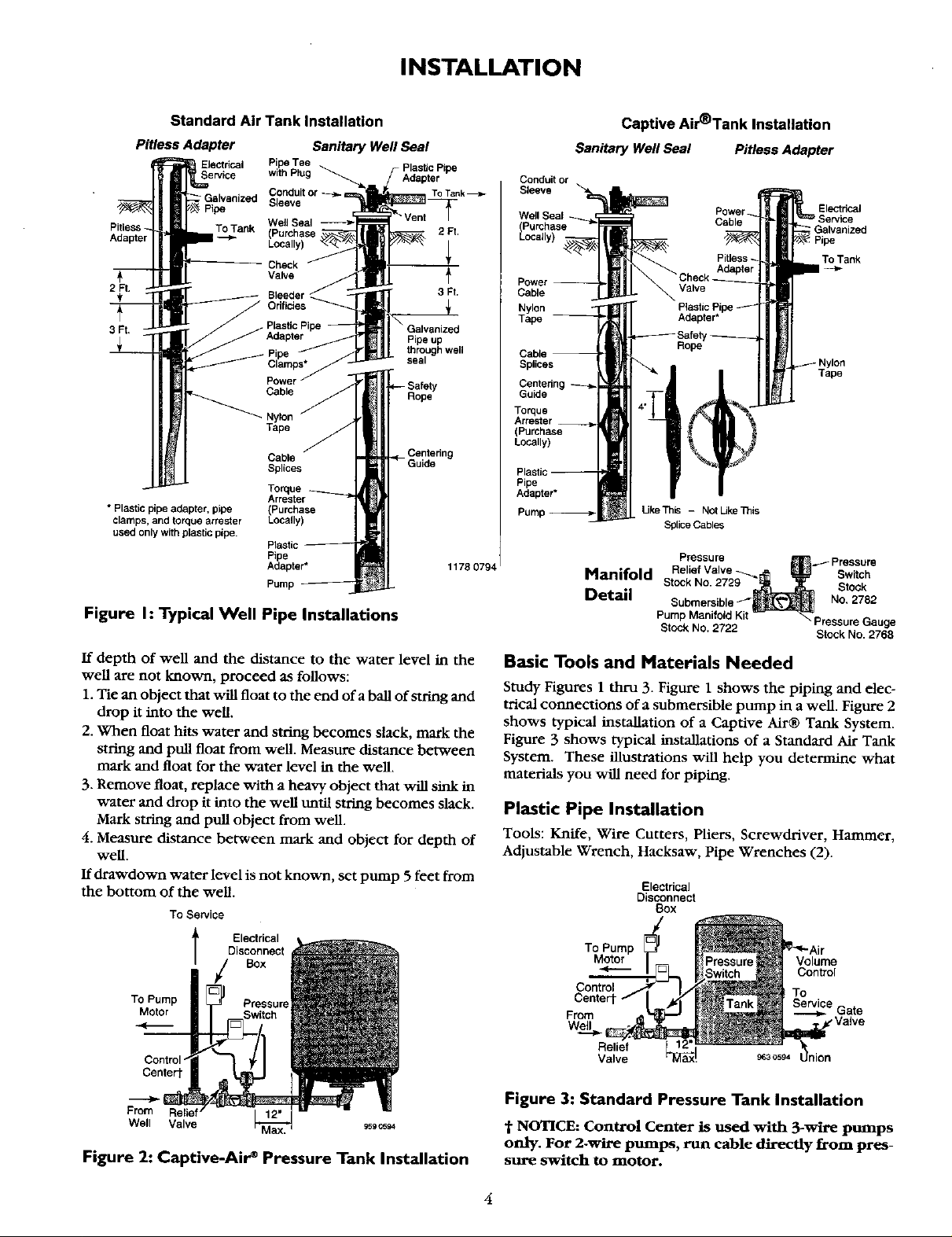
Figure I: Typical Well Pipe Installations
If depth of well and the distance to the water level in the
well are not known, proceed as follows:
1. Tie an object that will float to the end of a ball of string and
drop it into the well.
2. When float hits water and string becomes slack, mark the
string and pull float from well. Measure distance between
mark and float for the water level in the well.
3. Remove float, replace with a heavy object that will sink in
water and drop it into the well until string becomes slack.
Mark string and pull object from well.
4. Measure distance between mark and object for depth of
well.
If drawdown water level is not known, set pump 5 feet from
the bottom of the well.
To Sewice
l Ele_dcal
Disconnect
Box
To Pump Pressure
Motor
Control"
Centert
From
Well Valve
Figure 2: Captive-Air* Pressure Tank Installation
Captive Air'Tank Installation
SanitaryWellSeal PitlessAdapter
Conduit or
Sleeve
Well Seal
(Purchase
Locally)
Power
Cable
Nylon
Tape --
Electrical
; Galvanized
To Tank
Splices
Tape
Torque
Arrester
(Purchase
Locally)
Pipe
Adapter•
UkeTh_ - NotUkeTnis
Splice Cables
Manifold
Detail
Pressure
• ._ Pressure
Relief Valve _ Sw tch
Stock No. 2729 Stock
Submersible/" No, 2782
P_cP Marlin2 dKit Pressure Gauge
• Stock No. 2768
Basic Tools and Materials Needed
Study Figures 1 thru 3. Figure 1 shows the piping and elec-
trical connections of a submersible pump in a well. Figure 2
shows typical installation of a Captive Air® Tank System•
Figure 3 shows typical installations of a Standard Air Tank
System• These illustrations will help you determine what
materials you will need for piping.
Plastic Pipe Installation
Tools: Knife, Wire Cutters, Pliers, Screwdriver, Hammer,
Adjustable Wrench, Hacksaw, Pipe Wrenches (2).
Electrical
Disconnect
(3ox
To Pump
Motor
Volume
Control
Control
Centert
From e Gate
Wel_l ,Valve
Relief
Valve ss3c594
Figure 3: Standard Pressure Tank Installation
"i"NOTICE: Control Center is used with 3-wire pumps
only. For 2-wire pumps, run cable directly from pres-
sure switch to motor.
4
INSTALLATION
Materials: Plastic Pipe and Fittings (as required to complete
job); Teflon Tape (DO NOT use pipe joint compound on
plastic fittings); Centering Guides - Stock No. 2724.
Galvanized Steel Pipe Installation
Tools: Knife, Wire Cutters, Pliers, Screwdriver, Hammer,
Adjustable Wrench, Hacksaw, Pipe Wrenches (2), Pipe
Cutting and Threading Tools.
Materials: Galvanized Pipe and Fittings (as required to com-
plete job); Pipe Joint Compound or Teflon Tape; Centering
Guides - Stock No. 2724.
Safety Pressure Relief Valve Stock No. 2729
For your protection, install this pressure relief valve.
Purchase from your local Sears Store.
This relief valve is designed to protect home water systems
from excessive pressure. It is factory preset to start relieving
pressure at 75 PSI (pounds per square inch). Use only on
home water systems with pumps listed in this Owners
Manual.
1. For maximum protection, locate valve within 2 ft. of the
pressure tank.
2. Install valve directly in pipe tee. Do not use any reducers
or pipe extensions. Tee must be located in main pump
supply line to tank. See diagram Page 4.
3. Protect relief valve from freezing, dirt, and any other pos-
sible damage that would cause the valve not to function.
4. Long lengths of pipe or hose connected to the relief valve
discharge port can limit the amount of water and pressure
that can be relieved, ff necessary to pipe away from relief
valve, use minimum 1-1/4" plastic pipe.
5. Protect everything in the immediate area of the relief valve
from water damage in the event the relief valve operates.
Gauge
A Pressure Gauge, Stock No. 2768, can be installed. It will
indicate the pressure at which pump starts and stops and
any pressure in between.
The Motor
The motor is water filled type, and is ready to run as received.
Pressure Switch
Install an automatic pressure switch (Stock No. 2782) set to
start pump at 40 lbs. pressure and stop pump when the sys-
tem pressure reaches 60 lbs. See Figures 2 and 3, Page 4.
Tank
The tank serves two functions. It provides a reservoir of
water, which can be drawn off through the house fixture.
The tank maintains a cushion of air under pressure. When
tank pressure falls far enough, pump will start.
Two types of tanks are available: Captive Air® and Standard.
The Air Volume Control (AVC) maintains the cushion of air
in Standard Tanks. No Air Volume Control is needed with a
Captive Air® Tank.
Air Volume Control
A device mounted on a standard tank in order to keep
enough air in the tank to prevent waterlogging the tank.
Operating a water system with no air cushion in the pres-
sure tank can cause water hammer, rapid pump cycling, and
damage to the system.
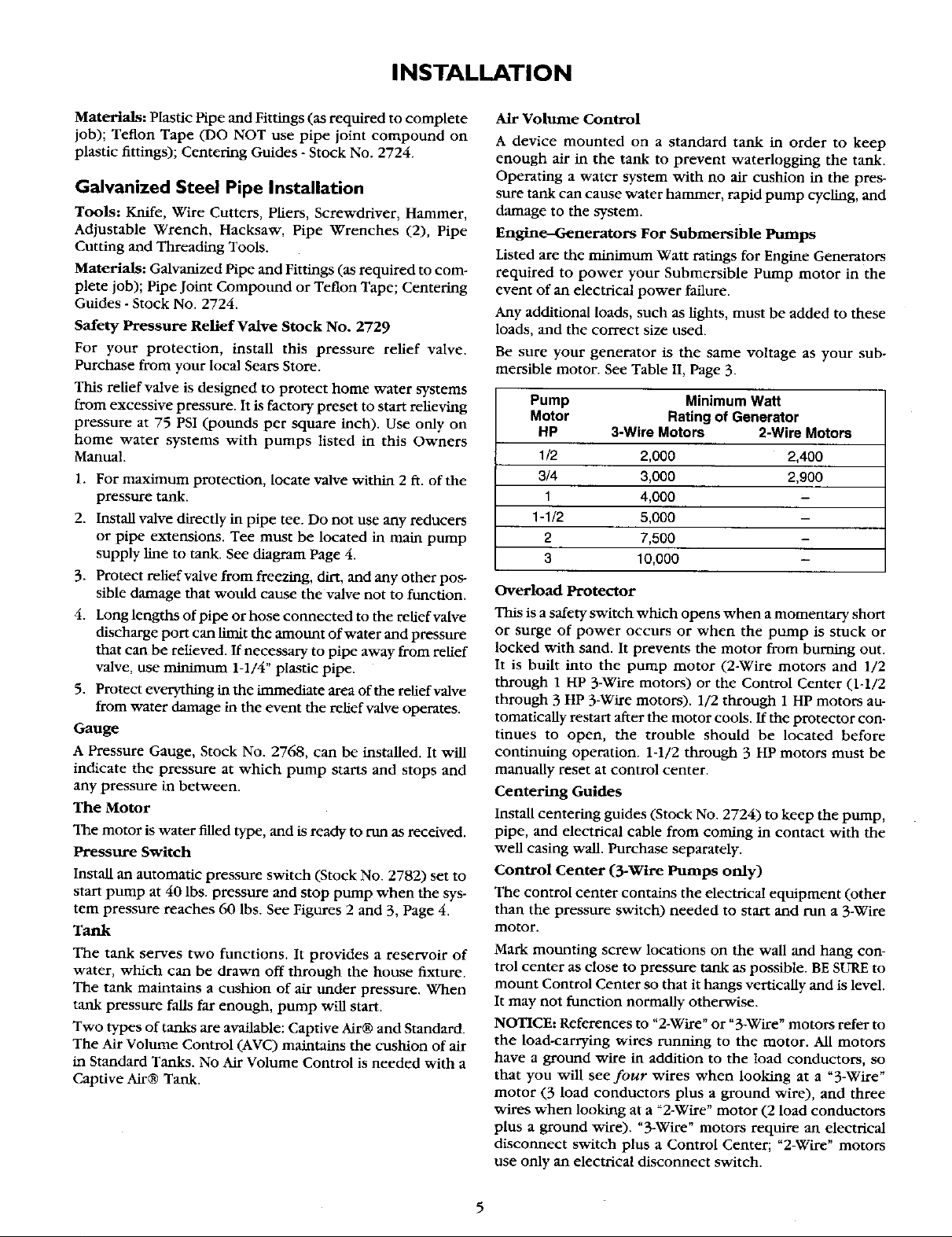
Engine--Generators For Submersible Pumps
Listed are the minimum Watt ratings for Engine Generators
required to power your Submersible Pump motor in the
event of an electrical power failure.
Any additional loads, such as lights, must be added to these
loads, and the correct size used.
Be sure your generator is the same voltage as your sub-
mersible motor. See Table II, Page 3.
Pump Minimum Watt
Motor Rating of Generator
HP 3-Wire Motors 2-Wire Motors
1/2 2,000 2,400
3/4 3,000 2,900
1 4,000 -
1-1/2 5,000 -
2 7,500 -
3 10,000 -
Overload Protector
This is a safety switch which opens when a momentary short
or surge of power occurs or when the pump is stuck or
locked with sand. It prevents the motor from burning out.
It is built into the pump motor (2-Wire motors and 1/2
through 1 HP 3-Wire motors) or the Control Center (1-1/2
through 3 HP 3-Wire motors). 1/2 through 1 HP motors au-
tomatleally restart after the motor cools. If the protector con-
tinues to open, the trouble should be located before
continuing operation. 1-1/2 through 3 HP motors must be
manually reset at control center.
Centering Guides
Install centering guides (Stock No. 2724) to keep the pump,
pipe, and electrical cable from coming in contact with the
well casing wall. Purchase separately.
Control Center (3-Wire Pumps only)
The control center contains the electrical equipment (other
than the pressure switch) needed to start and run a 3-Wire
motor.
Mark mounting screw locations on the wall and hang con-
trol center as close to pressure tank as possible. BE SURE to
mount Control Center so that it hangs vertically and is level.
It may not function normally otherwise.
NOTICE: References to "2-Wire" or "3-Wire" motors refer to
the load-carrying wires running to the motor. All motors
have a ground wire in addition to the load conductors, so
that you will see four wires when looking at a "3-Wire"
motor (3 load conductors plus a ground wire), and three
wires when looking at a _2-Wire" motor (2 load conductors
plus a ground wire). "3-Wire" motors require an electrical
disconnect switch plus a Control Center; "2-Wire" motors
use only an electrical disconnect switch.
 Loading...