


215132_Bil_oipm_V1:PN30635.00 4/14/2009 5:38 PM Page 1
Operator’s Manual
2 x 42″ Belt
6″ Disc
SANDER
Model No.
351.215132
Sears, Roebuck and Co., Hoffman Estates, IL 60179 U.S.A.
www.sears.com/craftsman
30635.00 Draft (04/01/09)
SAFETY
ASSEMBLY
OPERATION
MAINTENANCE
LIST PARTS
ESPAÑOL

215132_Bil_oipm_V1:PN30635.00 4/14/2009 5:38 PM Page 2
TABLE OF CONTENTS
Warranty. . . . . . . . . . . . . . . . . . . . . . . . . . . . . . . . . . . . 2
Safety Rules . . . . . . . . . . . . . . . . . . . . . . . . . . . . . . . 2-3
Unpacking . . . . . . . . . . . . . . . . . . . . . . . . . . . . . . . . . . 3
Assembly . . . . . . . . . . . . . . . . . . . . . . . . . . . . . . . . . 3-4
Installation. . . . . . . . . . . . . . . . . . . . . . . . . . . . . . . . . 4-5
Operation . . . . . . . . . . . . . . . . . . . . . . . . . . . . . . . . . 5-8
Maintenance. . . . . . . . . . . . . . . . . . . . . . . . . . . . . . . . . 8
Troubleshooting . . . . . . . . . . . . . . . . . . . . . . . . . . . . . . 9
Parts Illustration and List . . . . . . . . . . . . . . . . . . . 10-11
Español . . . . . . . . . . . . . . . . . . . . . . . . . . . . . . . . . 12-19
WARRANTY
ONE-YEAR FULL WARRANTY ON CRAFTSMAN TOOL
If this Craftsman tool fails due to a defect in material or workmanship within one year from the date of purchase, call 1-800-4-MY-HOME® TO ARRANGE FOR FREE REPAIR (or replacement if repair proves impossible). This warranty does not include expendable parts, such as lamps, batteries, bits or blades.
If this tool is ever used for commercial or rental purposes, this warranty will apply for only 90 days from the date of purchase.
This warranty gives you specific legal rights and you may also have other rights which vary from state to state.
Sears, Roebuck and Co., Hoffman Estates, IL 60179
SAFETY RULES
WARNING: For your own safety, read all of the instructions and precautions before operating tool.
PROPOSITION 65 WARNING: Some dust created by power sanding, sawing, grinding, drilling and other construction activities contains chemicals known to the state of California to cause cancer, birth defects or other reproductive harm.
Some examples of these chemicals are:
•Lead from lead-based paints.
•Crystalline silica from bricks and cement and other masonry products.
•Arsenic and chromium from chemically-treated lumber.
Your risk from these exposures vary, depending on how often you do this type of work. To reduce your exposure to these chemicals: work in a well ventilated area and work with approved safety equipment. Always wear OSHA/NIOSH approved, properly fitting face mask or respirator when using such tools.
CAUTION: Always follow proper operating procedures as defined in this manual even if you are familiar with use of this or similar tools. Remember that being careless for even a fraction of a second can result in severe personal injury.
CAUTION: Always follow proper operating procedures as defined in this manual even if you are familiar with use of this or similar tools. Remember that being careless for even a fraction of a second can result in severe personal injury.
BE PREPARED FOR JOB
•Wear proper apparel. Do not wear loose clothing, gloves, neckties, rings, bracelets or other jewelry which may get caught in moving parts of machine.
•Wear protective hair covering to contain long hair.
•Wear safety shoes with non-slip soles.
•Wear safety glasses complying with United States ANSI Z87.1. Everyday glasses have only impact resistant lenses. They are NOT safety glasses.
•Wear face mask or dust mask if operation is dusty.
•Be alert and think clearly. Never operate power tools when tired, intoxicated or when taking medications that cause drowsiness.
PREPARE WORK AREA FOR JOB
•Keep work area clean. Cluttered work areas invite accidents.
•Do not use power tools in dangerous environments. Do not use power tools in damp or wet locations. Do not expose power tools to rain.
•Work area should be properly lighted.
•Proper electrical receptacle should be available for tool. Three-prong plug should be plugged directly into properly grounded, three-prong receptacle.
•Extension cords should have a grounding prong and the three wires of the extension cord should be of the correct gauge.
•Keep visitors at a safe distance from work area.
•Keep children out of workplace. Make workshop childproof. Use padlocks, master switches or remove switch keys to prevent any unintentional use of power tools.
TOOL SHOULD BE MAINTAINED
•Always unplug tool prior to inspection.
•Consult manual for specific maintaining and adjusting procedures.
•Keep tool lubricated and clean for safest operation.
•Remove adjusting tools. Form habit of checking to see that adjusting tools are removed before switching machine on.
•Keep all parts in working order. Check to determine that the guard or other parts will operate properly and perform their intended function.
•Check for damaged parts. Check for alignment of moving parts, binding, breakage, mounting and any other condition that may affect a tool’s operation.
•A guard or other part that is damaged should be properly repaired or replaced. Do not perform makeshift repairs. (Use parts list provided to order replacement parts.)
© Sears, Roebuck and Co. |
2 |
|
215132_Bil_oipm_V1:PN30635.00 4/14/2009 5:38 PM Page 3
KNOW HOW TO USE TOOL
•Use right tool for job. Do not force tool or attachment to do a job for which it was not designed.
•Disconnect tool when changing belt or abrasive disc.
•Avoid accidental start-up. Make sure that the switch is in the “OFF” position before plugging in.
•Do not force tool. It will work most efficiently at the rate for which it was designed.
•Keep hands away from moving parts and sanding surfaces.
•Never leave tool running unattended. Turn the power off and do not leave tool until it comes to a complete stop.
•Do not overreach. Keep proper footing and balance.
•Never stand on tool. Serious injury could occur if tool is tipped or if belt or disc are unintentionally contacted.
•Know your tool. Learn the tool’s operation, application and specific limitations.
•Use recommended accessories (refer to page 11). Use of improper accessories may cause risk of injury to persons.
•Handle workpiece correctly. Protect hands from possible injury.
•Turn machine off if it jams. Belt jams when it digs too deeply into workpiece. (Motor force keeps it stuck in the work.)
•Support workpiece with miter gauge, belt platen, work stop or work table.
•Maintain 1/16″ maximum clearance between table and sanding belt or disc.
CAUTION: Think safety! Safety is a combination of operator common sense and alertness at all times when tool is being used.
WARNING: Do not attempt to operate tool until it is completely assembled according to the instructions.
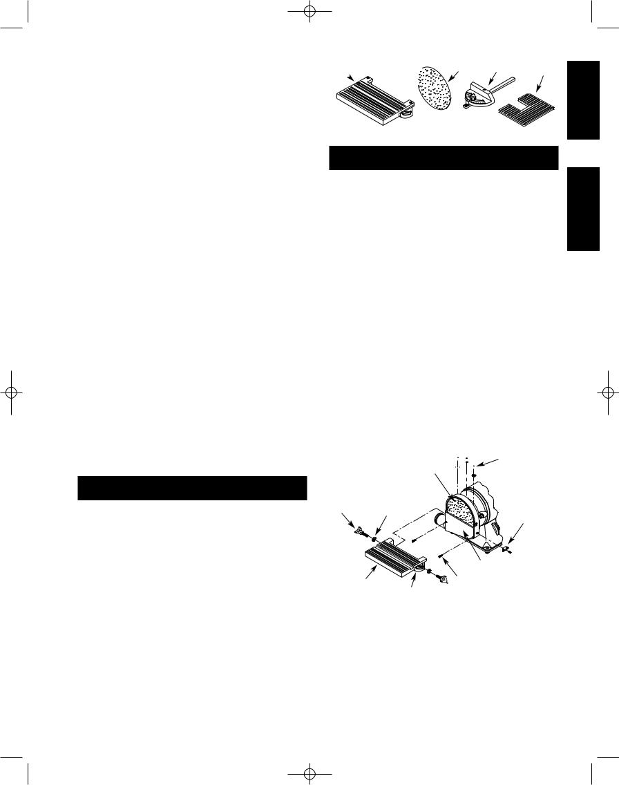
UNPACKING
Refer to Figure 1.
Check for shipping damage. If damage has occurred, a claim must be filed with the carrier for fastest action.
Parts which need to be fastened to the unit should be located and accounted for:
ADisc Table
BAbrasive Disc
CMiter Gauge Assembly
DBelt Table
Parts bag includes: horizontal stop bar, work stop, two knobs, two pointers, one 10-1.5 x 25mm socket head bolt, two 4-0.7 x 8mm socket head bolts, one 10mm lock washer, one 10mm flat washer, one 8mm flat washer, two 6mm flat washers, two 4 mm flat washers, one 8-1.25mm hex nut, one each 3, 5, 6, and 8mm hex wrenches and one extra long 4mm hex wrench.
A
 B C D
B C D
Figure 1 - Unpacking
ASSEMBLY
Refer to Figures 2 and 3.
CAUTION: Do not attempt assembly if parts are missing. Use operator’s manual to order replacement parts.
ATTACH ABRASIVE DISC TO ALUMINUM DISC
Refer to Figure 2.
•Remove dust chute by loosening screws and bolts.
•Remove the adhesive cover from the back of the abrasive disc.
•Center abrasive on aluminum disc and press to paste.
•Make sure abrasive is pasted evenly on the aluminum disc.
•Replace dust chute
ATTACH DISC TABLE
Refer to Figure 2.
•Set the disc table at right angle to the aluminum disc and secure the table position using two knobs and flat washers. Be sure that the gap between abrasive disc and disc table is 1/16″ or less.
•Attach pointers to sides of dust chute using 4-0.7 x 8mm socket head bolts from hardware bag. Adjust pointers to zero mark on trunnion and tighten bolts.
Aluminum Disc 

 Bolts with Abrasive

Knob |
Flat Washer |
|
Pointer
Dust Chute
Screw
Disc Table
Trunnion
Figure 2 - Secure Disc Table and Aluminum Disc
ATTACH BELT TABLE
Refer to Figure 3, page 4.
•Attach belt table to left side of belt housing using the socket head bolt, flat washer and lock washer from the hardware bag.
•Set the belt table at right angle to the belt.
•Be sure that gap between belt table and belt is 1/16″ or less.
SAFETY
ASSEMBLY
3
215132_Bil_oipm_V1:PN30635.00 4/14/2009 5:38 PM Page 4
• Tighten socket head bolt to secure belt table position.
ATTACH HORIZONTAL STOP
Refer to Figure 3.
A horizontal stop bar with nut is provided as a positive stop when using the sander with the belt housing adjusted to a horizontal position. To attach stop bar:
•Thread the horizontal stop bar into the threaded hole on the rear side of belt housing.
•Tighten hex nut.
Horizontal |
|
Stop Bar |
Belt Table |
|
Lock Washer |
|
Flat Washer |
Figure 3 - Attach Belt Table |
Socket Head Bolt |
|
INSTALLATION
Refer to Figures 4 and 5.
POWER SOURCE
WARNING: Do not connect sander to the power source until all assembly steps have been completed.
The motor is designed for operation on the voltage and frequency specified. Normal loads will be handled safely on voltages not more than 10% above or below specified voltage. Running the unit on voltages which are not within range may cause overheating and motor burnout. Heavy loads require that voltage at motor terminals be no less than the voltage specified on nameplate.
•Power supply to the motor is controlled by a single pole locking rocker switch. Remove the key to prevent unauthorized use.
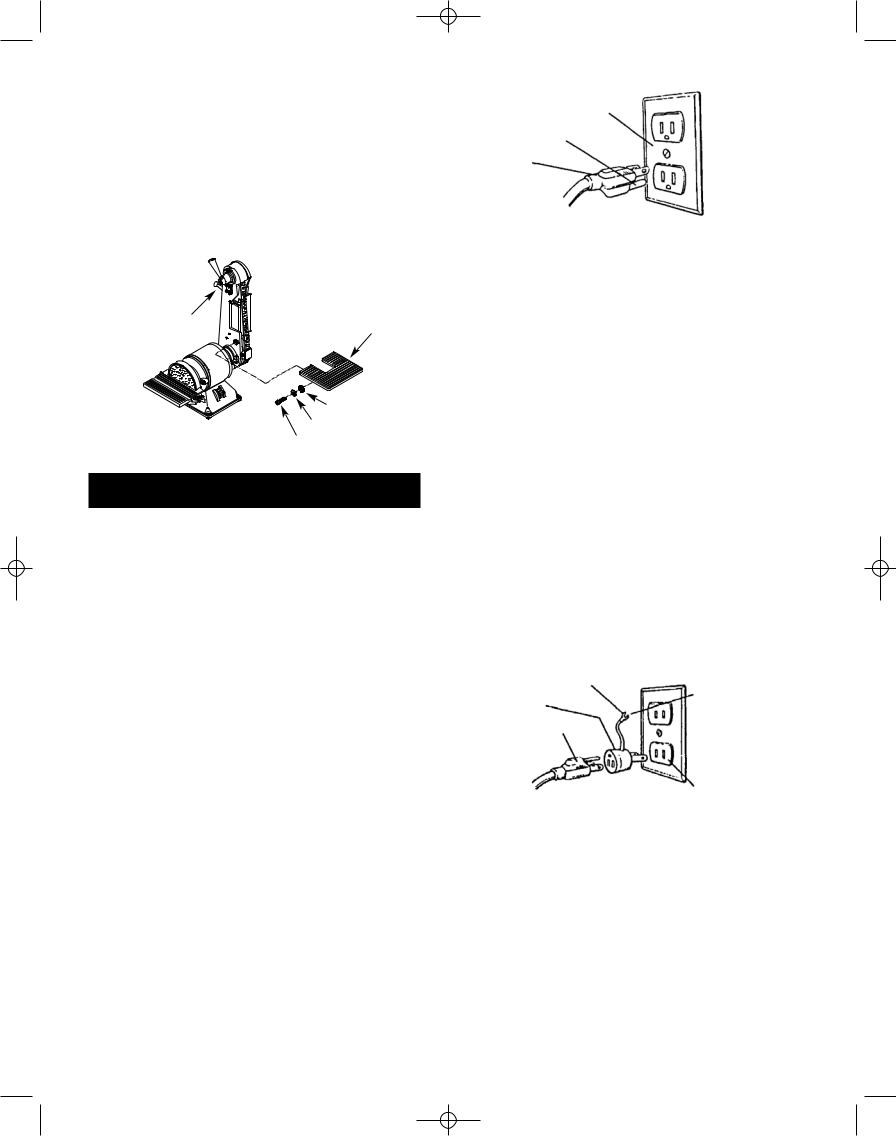
GROUNDING INSTRUCTIONS
WARNING: Improper connection of equipment grounding conductor can result in the risk of electrical shock. Equipment should be grounded while in use to protect operator from electrical shock.
•Check with a qualified electrician if grounding instructions are not understood or if in doubt as to whether the tool is properly grounded.
•This tool is equipped with an approved 3-conductor cord rated at 300V and a 3-prong grounding type plug (see Figure 4) for your protection against shock hazards.
•Grounding plug should be plugged directly into a properly installed and grounded 3-prong groundingtype receptacle, as shown (Figure 4).
Properly Grounded Outlet
Grounding Prong
3-Prong Plug
Figure 4 - 3-Prong Receptacle
•Do not remove or alter grounding prong in any manner. In the event of a malfunction or breakdown, grounding provides a path of least resistance for electrical shock.
WARNING: Do not permit fingers to touch the terminals of plug when installing or removing from outlet.
•Plug must be plugged into matching outlet that is properly installed and grounded in accordance with all local codes and ordinances. Do not modify plug provided. If it will not fit in outlet, have proper outlet installed by a qualified electrician.
•Inspect tool cords periodically, and if damaged, have repaired by an authorized service facility.
•Green (or green and yellow) conductor in cord is the grounding wire. If repair or replacement of the electric cord or plug is necessary, do not connect the green (or green and yellow) wire to a live terminal.
•Where a 2-prong wall receptacle is encountered, it must be replaced with a properly grounded 3-prong receptacle installed in accordance with National Electric Code and local codes and ordinances.
WARNING: This work should be performed by a qualified electrician.
A temporary 3-prong to 2-prong grounding adapter (see Figure 5) is available for connecting plugs to a two pole outlet if it is properly grounded.
Grounding Lug |
Make Sure |
|
This Is |
||
|
||
Adapter |
Connected |
|
3-Prong Plug |
To A Known |
|
Ground |
||
|
2-Prong |
|
|
Receptacle |
Figure 5 - 2-Prong Receptacle with Adapter
•Do not use a 3-prong to 2-prong grounding adapter unless permitted by local and national codes and ordinances.
(A 3-prong to 2-prong grounding adapter is not permitted in Canada.) Where permitted, the rigid green tab or terminal on the side of the adapter must be securely connected to a permanent electrical ground such as a properly grounded water pipe, a properly grounded outlet box or a properly grounded wire system.
•Many cover plate screws, water pipes and outlet boxes are not properly grounded. To ensure proper ground, grounding means must be tested by a qualified electrician.
4

215132_Bil_oipm_V1:PN30635.00 4/14/2009 5:38 PM Page 5
EXTENSION CORDS
•The use of any extension cord will cause some drop in voltage and loss of power.
•Wires of the extension cord must be of sufficient size to carry the current and maintain adequate voltage.
•Use the table to determine the minimum wire size (A.W.G.) extension cord.
•Use only 3-wire extension cords having 3-prong grounding type plugs and 3-pole receptacles which accept the tool plug.
•If the extension cord is worn, cut, or damaged in any way, replace it immediately.
Extension Cord Length
Wire Size. . . . . . . . . . . . . . . . . . . . . . . . . . . . . . . A.W.G.
Up to 25 ft. . . . . . . . . . . . . . . . . . . . . . . . . . . . . . . . . . 18
25 to 50 ft. . . . . . . . . . . . . . . . . . . . . . . . . . . . . . . . . . 16
NOTE: Using extension cords over 50 ft. long is not recommended.
MOTOR
The sander is assembled with motor and wiring installed as an integral part of the tool.
The permanently split capacitor motor has the following specifications:
Horsepower (Continuous Duty) . . . . . . . . . . . . . . . . . . 1/3
Voltage . . . . . . . . . . . . . . . . . . . . . . . . . . . . . . . . . . . 120
Amps . . . . . . . . . . . . . . . . . . . . . . . . . . . . . . . . . . . . . 3.5
Hertz . . . . . . . . . . . . . . . . . . . . . . . . . . . . . . . . . . . . . 60
Phase . . . . . . . . . . . . . . . . . . . . . . . . . . . . . . . . . . Single
RPM . . . . . . . . . . . . . . . . . . . . . . . . . . . . . . . . . . . . 3500
Rotation (viewed from left side) . . . . . . . . . . . Clockwise
ELECTRICAL CONNECTIONS
WARNING: All electrical connections must be performed by a qualified electrician. Make sure tool is off and disconnected from power source while motor is mounted, connected, reconnected or anytime wiring is inspected.
Motor is assembled with approved, 3-conductor cord to be used at 120 volts. Motor is prewired at the factory for 120 volts.
The power lines are inserted directly onto the switch. The green ground line must remain securely fastened to the frame to properly protect against electrical shock. The power supply to the motor is controlled by a single pole locking rocker switch.
• Remove the key to prevent unauthorized use.
OPERATION
Refer to Figures 6-14.
DESCRIPTION
Craftsman 2 x 6″ Belt and Disc Sander has a 2″ x 42″ belt and 6″ disc for deburring, beveling and sanding wood, plastic and metal. The sander has a fan-cooled 1/3
HP continuous duty motor. Belt speed is 4400 FPM and the disc rotates 3500 RPM. The belt table tilts 0 to 60° and the disc table tilts 0 to 45° for angle sanding. The quick release tension and tracking mechanism makes belt changing quick and easy. Belt platen is removable for contour sanding. Belt housing swivels from vertical to horizontal for sanding large workpieces. Disc guard has 11/2″ dust collection chute.
SPECIFICATIONS
Belt size . . . . . . . . . . . . . . . . . . . . . . . . . 2 x 42″, 80 grit
Belt platen area . . . . . . . . . . . . . . . . . . . . . . . . . 2 x 71/4″
Belt table dimensions . . . . . . . . . . . . . . . . . . . . 9 x 6¾″
Belt table tilts . . . . . . . . . . . . . . . . . . . . . . . . . . . 0 to 60°
Belt speed . . . . . . . . . . . . . . . . . . . . . . . . . . . 4400 FPM
Disc diameter . . . . . . . . . . . . . . . . . . . . . . . . . . . . . . . 6″
Disc table dimensions . . . . . . . . . . . . . . . . . . 83/16 x 57/16″
Disc table tilts . . . . . . . . . . . . . . . . . . . . . . . . . . 0 to 45°
Disc dust chute diameter . . . . . . . . . . . . . . . . . . . . . 11/2″
Disc speed . . . . . . . . . . . . . . . . . . . . . . . . . . 3500 RPM
Base dimensions . . . . . . . . . . . . . . . . . . . . . . 91/16 x 89/32″
Switch . . . . . . . . . . . . . . . . . . . . . . . . SP, Locking rocker
Weight . . . . . . . . . . . . . . . . . . . . . . . . . . . . . . . . . 32 lbs
Shipping weight . . . . . . . . . . . . . . . . . . . . . . . . . . 35 lbs WARNING: Operation of any power tool can result in foreign objects being thrown into the eyes, which can result in severe eye damage. Always wear safety goggles complying with United States ANSI Z87.1 (shown on package) before commencing power tool operation. Safety goggles are available at Sears retail stores or catalog.
CAUTION: Always observe following safety precautions.
SAFETY PRECAUTIONS
•Whenever adjusting or replacing any parts on the tool, turn switch OFF and remove the plug from power source.
•Recheck table knobs. They must be tightened securely.
•Make sure all guards are properly attached. All guards should be securely fastened.
•Make sure all moving parts are free and clear of any interference.
•Make sure all fasteners are tight and have not vibrated loose.
•With power disconnected, test operation by hand for clearance and adjust if necessary.
•Always wear eye protection or face shield.
•Make sure abrasive belt always tracks properly. Correct tracking gives optimum performance.
•After turning switch on, always allow belt to come up to full speed before sanding or grinding.
•Be sure motor runs clockwise on disc side. Abrasive belt must travel down.
OPERATION
5

215132_Bil_oipm_V1:PN30635.00 4/14/2009 5:38 PM Page 6
•Avoid kickback by sanding in accordance with the directional arrows.
•Keep your hands clear of abrasive belt, disc and all moving parts.
•For optimum performance, do not stall motor or reduce speed. Do not force the work into the abrasive.
•Support workpiece with belt table when sanding with belt, with disc table when sanding with disc.
•Never push a sharp corner of the workpiece rapidly against the belt or disc. Abrasive backing may tear.
•Replace abrasives when they become loaded (glazed) or frayed.
•When grinding metal, move workpiece across abrasive to prevent heat built up.
•Never attempt wet sanding. If the workpiece becomes too hot to handle, cool it in water.
MOUNT SANDER
During operation the sander may have a tendency to slide or move about on the bench or table. It is recommended to mount the sander onto a stand or to a bench top.
ADJUSTING BELT TABLE
Refer to Figure 6.
WARNING: Disconnect sander from power source before making any adjustments.
•To adjust belt table angle, loosen the socket head bolt and adjust table to desired angle. Use a combination square to set belt table at 45° or 60° from belt platen.
•Adjust for 1/16″ maximum clearance between the belt and the table.
•Secure table position by tightening bolt.
Socket |
Belt Cover |
Head Bolt |
Knob
 Belt Platen

 Bracket


 Socket Head
Bolt
Belt Table
Socket Head Bolt
Figure 6 - Adjustments
REPLACING ABRASIVE BELT
Refer to Figures 6 and 7.
WARNING: Disconnect sander from power source before making any adjustments.
•Sanding belt should be replaced when worn, torn, or glazed.
•Loosen and remove two knobs from belt cover.
•Remove belt cover.
•Loosen and remove socket head bolt from bracket.
•Remove bracket.
•Loosen socket head bolt and move belt table parallel to belt.
•Release belt tension by pulling down on handle assembly. Slide old belt off the drive and tracking wheels.
NOTE: There may be an arrow on the inside of the belt. The arrow should point in the direction of belt travel to ensure that the splice in the belt will not come apart.
•Pull down on the handle and slide new belt over the drive and idler wheels. Center belt on wheels.
•Rotate belt by hand to check tracking. Belt should ride centered on wheels.
•If belt does not ride centered on wheels, adjust belt tracking as described in the next section.
•Replace belt cover and secure it with two knobs.
•Replace bracket and secure it with socket head bolt.
•Reset belt table to be at the desired angle, and secure it by tightening the bolt.
Idler Wheel
Handle
Belt
Drive Wheel
Figure 7 - Replace Abrasive Belt
TRACKING ABRASIVE BELT
Refer to Figure 8, page 7.
•Test the tracking. Plug in power cord. Turn switch ON and immediately OFF. If the abrasive belt is centered on wheels and did not move to the right or left, it is tracking properly. If the belt moved to the right or left, adjustment is necessary.
•To adjust the tracking wheel, loosen the locking nut on adjusting bolt. Use a 4mm hex wrench to turn adjusting bolt.
•If the abrasive belt moves to the left, turn the bolt counterclockwise. If belt moves to the right, turn the bolt clockwise.
•Lock the position when the belt is tracking properly so the belt will remain centered on the wheels. Hold the position of the bolt with the 4mm hex wrench.
Tighten locking nut to secure bolt position.
6
 Loading...