


Operator's Manual
®
48" GT DOZER BLADE
For Garden Tractors with 23" Tires
Model No. 486.24414
 Before using this product, read this manual and follow all Safety Rules and Operating Instructions.
CAUTION: DO NOT use this Dozer Blade on Lawn Tractors or on Garden Tractors with less than 23-inch diameter tires.
Sears, Roebuck and Co., Hoffman Estates, IL 60179 U.S.A. www.sears.com/craftsman
STOP
DO NOT RETURN TO STORE For Missing Parts or Assembly Questions Call 1-866-576-8388
•Safety
•Assembly
•Operation
•Maintenance
•Parts
PRINTED IN U.S.A. |
FORM NO. 49810 (REV. 3/06) |

TABLE OF CONTENTS
SAFETY RULES |
2 |
MAINTENANCE |
16 |
WARRANTY |
2 |
TROUBLESHOOTING |
16 |
CARTON CONTENTS |
3 |
STORAGE |
17 |
FULL SIZE HARDWARE CHART |
4-5 |
ACCESSORIES |
17 |
ASSEMBLY |
6-13 |
REPAIR PARTS ILLUSTRATION |
18 |
OPERATION |
14 |
REPAIR PARTS LIST |
19 |
SERVICE AND ADJUSTMENTS |
15 |
PARTS ORDERING/SERVICE |
BACK COVER |
SAFETY
Anypowerequipmentcancauseinjuryifoperatedimproperlyoriftheuserdoesnotunderstandhowtooperatetheequipment.
Exercise caution at all times when using power equipment.
1.Read the tractor and dozer blade owners manuals and know how to operate your tractor before using the tractor with the dozer blade attachment.
2.Never operate the tractor and dozer blade without wearing proper clothing suited to weather conditions and operation of controls.
3.Never allow children to operate the tractor and dozer blade. Do not allow adults to operate without proper instructions.
4.Always begin with transmission in fi rst (low) gear and gradually increase speed as required.
Look for this symbol to point out important safety precautions.It means — Attention!! Become alert!! Your safety is involved.
WARRANTY
ONEYEAR FULL WARRANTY
When operated and maintained according to the instructions supplied with it, if this Dozer Blade fails due to a defect in material or workmanship within one year from the date of purchase, call 1-800-4-MY-HOME® to arrange for free repair (or replacement if repair proves impossible).
If this product is used for commercial or rental purposes, this warranty applies for only 90 days from the date of purchase.
This warranty gives you specifi c legal rights, and you may also have other rights which vary from state to state.
Sears, Roebuck and Co., D817WA, Hoffman Estates, IL 60179
The model number and serial numbers will be found on a decal attached to the dozer blade.
You should record both the serial number and the date of purchase and keep in a safe place for future reference.
MODEL NUMBER: |
486.24414 |
SERIAL NUMBER: |
__________________ |
DATE OF PURCHASE: |
__________________ |
2
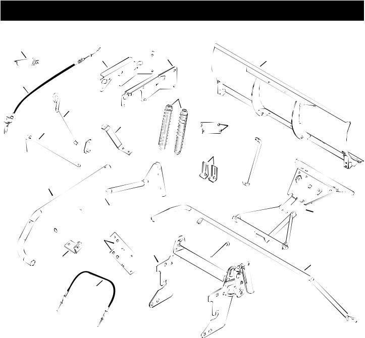
CARTON CONTENTS
1
3 |
4 |
5 |
2
|
9 |
7 |
|
8 |
10 |
6 |
|
11  12
12
14
|
15 |
13 |
|
|
|
|
17 |
|
16 |
|
18 |
|
19 |
|
|
|
CARTON CONTENTS |
6. |
Attachment Rod |
11. |
Skid Shoe (2) |
|
|
|
1. |
Grip Assembly |
16. |
Lift Bracket |
||||
2. |
Trigger with Cable |
7. |
Handle Guide |
12. |
Lift Rod |
17. |
Angle Lock Bar (2) |
3. |
Left Side Plate |
8. |
Blade Pivot Bracket |
13. |
Pivot Plate |
18. |
Frame Assembly |
4. |
Right Side Plate |
9. |
Trip Spring (2) |
14. |
Upper Lift Handle |
19. |
Handle Assembly |
5. |
Blade Assembly |
10. |
Lift Link (2) |
15. |
Lower Lift Handle |
20. Control Cable |
|
3

SHOWN FULL SIZE
A B C D  E
E  F
F 
 G H
G H
|
|
|
|
|
|
N |
|
O |
|
|
|
|
|
|
|
|
|
|
|
|
|
M |
|
|
|
|
|
|
K |
L |
|
|
|
|
|
|
J |
|
|
|
|
|
|
|
I |
|
|
S |
T |
|
|
U |
|
Q |
R |
|
|
|
|
|||
|
|
|
|
|
|
|
||
|
|
|
|
|
|
|
|
|
|
|
|
|
|
Y |
|
Z |
AA |
|
|
W |
X |
|
|
|
||
P |
|
|
|
|
|
|||
V |
|
|
|
|
|
|||
|
|
|
|
|
|
|
|
BB |
CC |
DD |
EE |
|
FF
NOT SHOWN FULL SIZE
KK
GG |
|
II |
JJ |
|
|
||
|
|
|
|
|
HH |
|
|
LL |
MM |
NN |
OO |
4

CONTENTS OF PARTS PACKAGE
|
|
|
REF. |
QTY. |
DESCRIPTION |
A |
2 |
Hex Bolt, 1/2" x 2-3/4" |
V |
11 |
Nylock Nut, 5/16" |
B |
2 |
Hex Bolt, 1/2" x 2" |
W |
4 |
Hex Nut, 1/2" |
C |
2 |
Hex Bolt, 1/2" x 1-1/2" |
X |
4 |
Hex Nut, 3/8" |
D |
2 |
Hex Bolt, 5/16" x 1-3/4" |
Y |
2 |
Short Spacer |
E |
2 |
Hex Bolt, 3/8" x 1-1/4" |
Z |
4 |
Lock Washer, 3/8" |
F |
4 |
Hex Bolt, 3/8" x 1" |
AA |
1 |
Oval Screw, #10 x 1" |
G |
2 |
Hex Bolt, 5/16" x 3/4" |
BB |
2 |
Washer, 3/4" |
H |
2 |
Hex Bolt, 3/8" x 3-1/2 |
CC |
8 |
Washer, 1/2" Large |
I |
1 |
Shoulder Bolt |
DD |
6 |
Washer, 5/8" SAE |
J |
6 |
Carriage Bolt, 3/8" x 1" |
EE |
4 |
Washer, 1/2" |
K |
2 |
Carriage Bolt, 3/8" x 1-1/4" |
FF |
4 |
Washer, 5/16" |
L |
6 |
Carriage Bolt, 5/16" x 1 |
GG |
1 |
Cable Mount Bracket |
M |
1 |
Hex Bolt, 5/16" x 1-1/2" |
HH |
2 |
Nylon Tie |
N |
2 |
Hex Bolt, 1/4" x 1-1/2" |
II |
2 |
Clevis Pin |
O |
4 |
Cotter Pin |
JJ |
2 |
Plastic Cap |
P |
4 |
Nylock Nut, 1/2" |
KK |
7 |
Haircotter Pin |
Q |
10 |
Nylock Nut, 3/8" |
LL |
2 |
Cable End Fitting |
R |
3 |
Nylock Nut, 1/4" |
MM |
1 |
Extension Spring |
S |
1 |
Whizlock Hex Nut, 3/8" |
NN |
1 |
Spring Pin |
T |
2 |
Hex Jam Nut, 5/16" |
OO |
1 |
Plastic Grip |
U |
1 |
Long Spacer |
|
|
|
5
ASSEMBLY
TOOLS REQUIRED FOR ASSEMBLY
(1)7/16" Wrench
(1)1/2" Wrench
(1)9/16" Wrench
(1)3/4" Wrench
(1)Adjustable Wrench
(1)Phillips Screwdriver
(1)Hammer
•Remove all parts and hardware packages from the carton. Lay out parts and hardware and identify using the illustrations on pages 3 and 4.
NOTE: Not all of the supplied parts and hardware will be needed for one particular tractor. Unneeded items may be discarded after assembly has been completed.
NOTE: Right hand (RH) and left hand (LH) are determined from the operator's position while seated on the tractor.
CAUTION: Do not begin assembling until the tractor engine, muffl er and exhaust defl ector have been allowed to cool off.
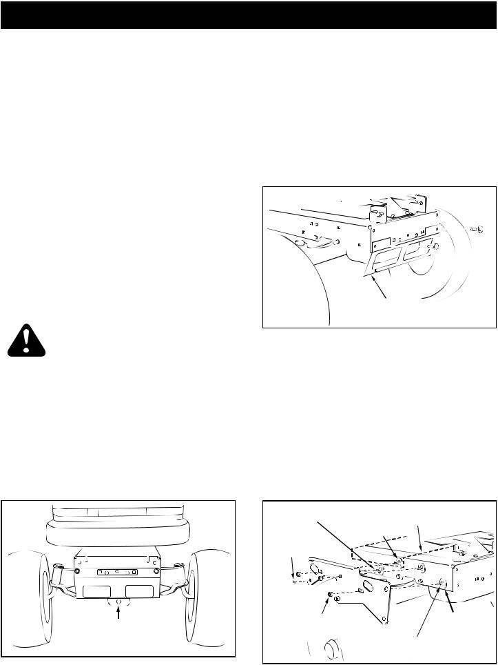
STEP 1: (SEE FIGURE 1)
•Look under the front of your tractor. If there is a single mower deck suspension bracket located underneath the middle of the front axle, continue on to step 2. If your tractor does not have a mower deck suspension bracket underneath the middle of the front axle, skip to step 5 on page 7 for tractors with dual suspension brackets.
FIGURE 1
INSTRUCTIONS FORTRACTORSWITH SINGLE FRONT DECK SUSPENSION BRACKET
STEP 2: (SEE FIGURE 2)
•Remove the tractor hood. Refer to your tractor owners manual for instructions on how to properly remove the hood.
•Remove the browning shield from the front of the tractor as shown. Hold onto the shield as you remove the second bolt to prevent it from falling.
NOTE: Reinstall the browning shield before using your tractor
FIGURE 2
STEP 3: (SEE FIGURE 3)
•Fasten the R.H. Side Plate (bend facing out) to the front three holes in the tractor frame using three 3/8" x 1" carriage bolts (J), three large 1/2" washers (CC) (see note) and three 3/8" nylock nuts (Q). For the rear hole, use a 5/16" x 1" carriage bolt (L), a large 1/2" washer (CC) and a 5/16" nylock nut (V). Place the 1/2" washers (V) between the tractor frame and the side plate.Tighten all bolts. Repeat for L.H. side plate.
•Reinstall the browning shield removed in fi gure 2.
NOTE: If the third bolt goes through an engine mounting plate (dotted lines) leave the 1/2" washer off that bolt.
5/16" x 1" CARRIAGE |
ENGINE MOUNTING |
BOLT (L) |
PLATE |
(SEE NOTE) |
|
5/16" NYLOCK |
|
NUT (V) |
|
3/8" NYLOCK |
LARGE 1/2" |
|
WASHER (CC) |
||
NUT (Q) |
||
|
3/8" x 1" CARRIAGE BOLT (J)
FIGURE 3
6
 Loading...