


APX290M/
APX490M
OPERATION/INSTALLA-
TION
MANUAL
MANUEL D'OPERATION/
INSTALLATION
MANUAL DE
OPERACIÓN/INSTALACIÓN

|
|
APX290M/APX490M Power System Amplifier |
|
|
INTRODUCTION |
||
|
The Clarion APX290M is a full-featured, two-channel amplifier incorporating the |
||
|
following features: |
||
English |
|||
• |
Specially coated circuit boards that resist mold, mildew and moisture damage. |
||
|
|||
|
• |
Pulse-Width Modulated (PWM) MOSFET power supply for maximum |
|
|
|
performance with minimal distortion. |
|
|
• |
Remote turn-on with "soft start" muting to prevent turn-on "thump". |
|
|
• |
Variable high-pass/low-pass electronic crossover with a 12dB per octave |
|
|
|
slope (adjustable range: 55Hz to 5.5kHz). |
|
|
• |
Variable bass boost circuit to reinforce low frequency signals that may be lost |
|
|
|
due to subwoofer enclosure design. |
|
|
• |
Adjustable input level controls with ground loop isolation to minimize noise |
|
|
|
and distortion. |
|
|
• |
2-ohm stereo stable, 4-ohm mono stable. |
|
|
• |
Gold-plated power, speaker, and RCA connectors. |
|
|
• |
Speaker level input. |
|
|
• |
Low profile construction with aluminum heat sink for efficient heat dissipation. |
|
The Clarion APX490M is a full featured, four-channel amplifier adding the following feature:
•Advanced circuitry design featuring bridgeable and mixed mode operation for use in various system configurations including 4, 3, or 2 channel systems.
ABOUT THE MANUAL AND WARRANTY
This manual describes the basic requirements to install the Clarion APX290M and APX490M amplifiers. The installation of this amplifier can be quite complex to install, if you do not posses the necessary knowledge and tools to perform this installation, please contact your local Clarion Marine Audio dealer.
Keep all instructions and sales receipt for future reference and warranty information. Warranty information can be found on page 18 of this manual.
TABLE OF CONTENTS |
|
Description . . . . . . . . . . . . . . . . . . . . . . . . . . . . . . . . . . . . . . . . . . . . . |
1 |
Input Connections and Audio Controls . . . . . . . . . . . . . . . . . . . . . . . . . |
2 |
Connections for Power and Speakers . . . . . . . . . . . . . . . . . . . . . . . . . |
4 |
Installation . . . . . . . . . . . . . . . . . . . . . . . . . . . . . . . . . . . . . . . . . . . . . . |
6 |
Mounting Precautions . . . . . . . . . . . . . . . . . . . . . . . . . . . . . . . . . . . . . |
6 |
Wiring Precautions . . . . . . . . . . . . . . . . . . . . . . . . . . . . . . . . . . . . . . . |
6 |
APX490M Wiring and Applications . . . . . . . . . . . . . . . . . . . . . . . . . . . . |
7 |
APX290M Wiring and Applications . . . . . . . . . . . . . . . . . . . . . . . . . . . . |
12 |
Setting the Gain . . . . . . . . . . . . . . . . . . . . . . . . . . . . . . . . . . . . . . . . . |
15 |
Setting the Crossover . . . . . . . . . . . . . . . . . . . . . . . . . . . . . . . . . . . . . |
15 |
Setting the Subwoofer Bass Boost . . . . . . . . . . . . . . . . . . . . . . . . . . . . |
15 |
Final System Check . . . . . . . . . . . . . . . . . . . . . . . . . . . . . . . . . . . . . . . |
16 |
Troubleshooting . . . . . . . . . . . . . . . . . . . . . . . . . . . . . . . . . . . . . . . . . . |
16 |
Product Specs . . . . . . . . . . . . . . . . . . . . . . . . . . . . . . . . . . . . . . . . . . . |
17 |
Clarion Limited Warranty . . . . . . . . . . . . . . . . . . . . . . . . . . . . . . . . . . . |
18 |
1
Operation/Installation Manual
DESCRIPTION
The APX290M and APX490M use an unregulated MOSFET power supply for superior sound and output wattage. In addition, a toroid-coil is used to transfer power with minimal performance loss due to heat. To avoid unwanted noise, a double-sided conformal printed circuit board with strategically placed components keeps AM RFI subdued.
All of the connections and controls for the APX290M and APX490M are conveniently located at the ends of the amplifier and labeled appropriately. To ensure the best possible electrical connections, the power, speaker, and RCA inputs are gold-plated. An additional benefit of the APX490M is the ability to create a 2, 3, or 4 channel amplified system with a flip of a switch (see Application section). In the event of component failure or a short circuit, the APX290M and APX490M incorporate safe guards and outboard ATC fuses to prevent damage to the amplifier.
INPUT CONNECTIONS AND AUDIO CONTROLS
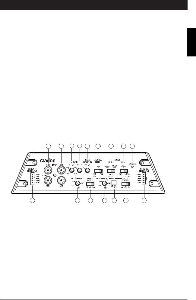
The front panel of the APX490M and APX290M contain both connections for RCA and speaker level inputs, along with the audio controls as shown below.
Fig. 1
APX490M
English
2 |
3 |
4 |
5 |
6 |
7 |
8 |
9 |
16 |
1 11 12 13 14 15 10
1. |
CH1/CH2 High Input |
9. |
CH 3/4 Mode Switch |
2. |
CH 1/2 RCA Input |
10. |
CH 3/4 High Input |
3. |
CH 3/4 RCA Input |
11. |
CH 1/2 Frequency Control |
4. |
CH1/CH2 Gain Control |
12. |
CH 1/2 Crossover Mode Switch |
5. |
CH 3/4 Gain Control |
13. |
CH 3/4 Frequency Control |
6. |
Bass Boost |
14. |
Frequency Range Multiplier |
7. |
Source Select |
15. |
CH 3/4 Crossover Mode Switch |
8. |
CH 1/2 Mode Switch |
16. |
Power Light Indicator |
2

English
APX290M/APX490M Power System Amplifier
APX290M
1 |
2 |
3 |
4 |
5 |
6 |
7 |
9 |
|
|
|
|
|
|
|
|
|
|
|
|
|
|
|
|
|
|
|
|
|
|
|
|
|
|
|
|
|
|
|
|
|
|
|
|
|
|
|
|
|
|
|
|
|
|
|
|
|
|
|
|
|
|
|
|
|
|
|
|
|
|
|
|
|
|
|
|
|
|
|
|
|
|
|
|
|
|
|
|
|
|
|
|
|
|
|
|
|
|
|
8 |
|
|
|
|
|
|
|
|
|
|
|||
1. CH1/CH2 RCA Input |
6. Crossover Mode |
|||||||||||||
2. |
Gain Control |
7. |
Output Mode Selector Switch |
|||||||||||
3. |
Bass Boost |
8. |
High Input |
|||||||||||
4. CH1/CH2 Frequency (Hz) |
9. Power Light Indicator |
|||||||||||||
5. |
Frequency Range Multiplier |
|
|
|
|
|
|
|
|
|||||
The RCA connections are gold plated for optimum performance and low signal loss. The RCA connectors are labeled CH 1 (front left), CH 2 (front right) [for APX490M: CH 3 (rear left), and CH 4 (rear right)]. In applications where RCA signals are not present, the speaker level output from the head unit can be used. (Use one or the other input, not both.)
•Gain Controls: For the APX490M, separate CH 1/2 and CH 3/4 gain controls allow you to set the nominal operating level of the amplifier. The amplifier's input range, 200mV to 6.0V for RCA inputs and 500mV to 13V for speaker level inputs, can accommodate input levels from virtually any head unit.
•Bass Boost: The amplifier features a "high-Q" (i.e. narrow frequency band)
Bass Boost circuit. It acts much like an equalizer with an adjustable gain from 0 to +15dB fixed at 45Hz. Use this feature to tune low-frequency audio response to compensate for a less than ideal subwoofer enclosure design. The added boost produces rich, full bass tones that are normally difficult to reproduce in the marine audio environment.
NOTE: Bass Boost setting should only be used for subwoofer applications.
•Source Select (APX490M only)
2 CH BASS: Uses CH 1/2 inputs and has output from all 4 channels with Bass Boost.
2 CH: Uses CH 1/2 inputs and has output from all 4 channels. The Bass Boost will work only on CH 1/2 and have no effect on CH 3/4.
4 CH: Uses all 4 channel inputs and has output from all 4 channels. The Bass Boost will work only on CH 1/2 and have no effect on CH 3/4.
3

Operation/Installation Manual
• Output Mode Selector Switch: CH 1/2 and CH 3/4 (APX490M only) |
|
|
STEREO: Full left and right stereo operation. |
|
|
CH 1Mono / CH 2 Mono: Single channel input for bridged operation. This is |
|
|
English |
||
• CH 1/2 FREQ / CH 3/4 FREQ (APX490M only) The CH 1/2 crossover frequencies |
||
especially useful in high-powered systems. (Uses CH 2 and CH 4 inputs.) |
|
|
CH 1/2 Mono / CH 3/4 Mono: Allows for a stereo input to be summed into a mono |
|
|
output. |
|
|
are adjustable from 55Hz to 550Hz. While CH 3/4 crossover frequencies are |
|
|
|
||
adjustable from 55Hz to 5500Hz (via the Frequency Range Multiplier) for a wider |
|
|
range of crossover points. Use this feature along with your speaker |
|
|
manufacturer's recommended crossover frequencies to quickly design a more |
|
|
advanced system. |
|
|
NOTE: If either of the Crossover Mode Switches is set to OFF, varying the |
|
|
frequency control will have no effect. |
|
|
• CH 1/2 Filter / CH 3/4 Filter (APX490M only) A filter is activated by sliding the CH |
|
|
1/2 and CH 3/4 filter switch to either HP = High Pass or LP = Low Pass. CH 1/2 is |
|
|
fully adjustable from 55-550Hz (via CH 1/2 Freq) and CH 3/4 is fully adjustable |
|
|
from 55-5500Hz (via CH 3/4 Frequency and Frequency Range Multiplier). Use |
|
|
this feature along with your speaker manufacture's recommended crossover |
|
|
frequencies to design a more advanced system. |
|
|
CONNECTIONS FOR POWER AND SPEAKERS |
|
|
The rear panel of the APX490M and APX290M contains power and speaker |
|
|
connections as shown below. |
|
Fig. 2
APX490M
1 |
2 |
3 |
4 |
5 |
6 |
|
|
|
|
|
|
|
|
|
|
|
|
|
|
|
|
|
|
|
|
|
|
|
|
|
|
|
|
|
|
|
|
|
|
|
|
|
|
|
|
|
|
|
|
|
|
|
|
|
|
|
|
|
|
|
|
|
|
|
|
|
|
|
|
|
|
|
|
|
|
|
|
|
|
|
|
|
|
|
|
|
|
|
|
|
|
|
|
|
|
|
|
|
|
|
|
|
|
|
|
|
|
|
|
|
|
|
|
|
|
|
|
|
|
|
|
|
|
|
|
|
|
|
|
|
|
|
|
|
|
|
|
|
|
|
|
|
|
|
|
|
|
|
|
|
|
|
|
|
|
|
|
|
|
|
|
|
|
|
|
|
|
|
|
|
|
|
|
|
|
|
|
|
|
|
|
|
|
|
|
|
|
|
|
|
|
|
|
|
|
|
|
|
|
|
|
|
|
|
|
|
|
|
|
|
|
|
|
|
|
|
|
|
|
|
|
|
|
|
|
|
|
|
|
|
|
|
|
|
|
|
|
|
|
|
|
|
|
|
|
|
|
|
|
|
|
|
|
|
|
|
|
|
|
|
|
|
|
|
|
|
|
|
|
|
|
|
|
|
|
|
|
|
|
|
|
|
|
|
|
|
|
|
|
|
|
|
|
|
|
|
|
|
|
|
|
|
|
|
|
|
|
|
|
|
|
|
|
|
|
|
|
|
|
|
|
|
|
|
|
|
|
|
|
|
|
|
|
|
|
|
|
|
|
|
|
|
|
|
|
|
|
|
|
|
|
|
|
|
|
|
|
|
|
|
|
|
|
|
|
|
|
|
|
|
|
|
|
|
|
|
|
|
|
|
|
|
|
|
|
|
|
|
|
|
|
|
|
|
|
|
|
|
|
|
|
|
|
|
|
|
|
|
|
|
|
|
|
|
|
|
|
|
|
|
|
|
|
|
|
|
|
|
|
|
|
|
|
|
|
|
|
|
|
|
|
|
|
|
|
7 |
|
|
|
|
8 |
|
|
|
|
|
|
|
|
|
|
|
|
|
|
|
|
|
|
|
|
|
|
|
|
|
|
|
|
||||||||||
1. CH1 Speaker Output |
|
|
|
|
|
|
|
|
|
|
|
|
|
|
|
|
5. Battery +12V Input |
||||||||||||||||||||||||||
2. CH2 Speaker Output |
|
|
|
|
|
|
|
|
|
|
|
|
|
|
|
|
6. 2 - 35 Amp Fuse |
||||||||||||||||||||||||||
3. Ground |
|
|
|
|
|
|
|
|
|
|
|
|
|
|
|
|
7. CH3 Speaker Output |
||||||||||||||||||||||||||
4. Remote Turn-on |
|
|
|
|
|
|
|
|
|
|
|
|
|
|
|
|
8. CH4 Speaker Output |
||||||||||||||||||||||||||
4

English
APX290M/APX490M Power System Amplifier
APX490M - Electrical Connection
Remote Turn-On |
F |
|
U |
|
S |
|
E |
Front Left Speaker (+) |
|
|
|
|
Rear Right Speaker (-) |
||||
|
||||
Front Left Speaker (-) |
Rear Right Speaker (+) |
|||
|
||||
Front Right Speaker (+) |
Rear Left Speaker (-) |
|||
Front Right Speaker (-) |
Rear Left Speaker (+) |
|||
Fig. 3
APX290M
1 |
2 |
3 |
4 |
5 |
6 |
|
|
|
|
|
|
|
|
|
|
|
|
|
|
|
|
|
|
|
|
|
|
|
|
|
|
|
|
|
|
|
|
|
|
|
|
|
|
|
|
|
|
|
|
|
|
|
|
|
|
|
|
|
|
|
|
|
|
|
|
|
|
|
|
|
|
|
|
|
|
|
|
|
|
|
|
|
|
|
|
|
|
|
|
|
|
|
|
|
|
|
|
|
|
|
|
|
|
|
|
|
|
|
|
|
|
|
|
|
|
|
|
|
|
|
|
|
|
|
|
|
|
|
|
|
|
|
|
|
|
|
|
|
|
|
|
|
|
|
|
|
|
|
|
|
|
|
|
|
|
|
|
|
|
|
|
|
|
|
|
|
|
|
|
|
|
|
|
|
|
|
|
|
|
|
|
|
|
|
|
|
|
|
|
|
|
|
|
|
|
1. CH1 Speaker Output |
|
|
|
|
|
|
|
4. Remote Turn-on |
|||||||||||||||||||||||||||||
2. CH2 Speaker Output |
|
|
|
|
|
|
|
5. Battery |
|||||||||||||||||||||||||||||
3. Ground |
|
|
|
|
|
|
|
6. 40 Amp Fuse |
|||||||||||||||||||||||||||||
APX290M - Electrical Connection
Remote Turn-On F
U
S
E
|
|
|
|
|
|
|
|
|
|
|
|
|
|
|
|
|
|
|
|
|
|
|
|
|
|
|
|
|
|
|
|
|
|
|
|
Left Speaker (-) |
|
|
|
Right Speaker (-) |
|
|
|
||||||||||
Left Speaker (+) |
Right Speaker (+) |
|
|
|
|||||||||||||
5
 Loading...