


 Loading...
Getting Started Guide for the Catalyst 2960-X and 2960-XR Switches
Getting Started with Your Switch 2
Box Contents 2
Running Express Setup 3
Managing the Switch 7
Planning and Installing a Switch Stack (Optional) 10
Installing the Switch 13
Connecting the FlexStack Cables (Optional) 19
Connecting to the Switch Ports 20
Troubleshooting 21
Related Documentation 23

Revised: December 3, 2013, OL-28310-02
Getting Started with Your Switch
This guide provides instructions on how to use Express Setup to initially configure your Catalyst switch. It also covers switch management options, basic rack-mounting, stacking guidelines, port and module connection procedures, and troubleshooting help.
Note Before installing or upgrading the switch, refer to the release notes.
Box Contents
Figure 1: Box Contents
1 |
Catalyst 2960-X switch1 |
9 |
Four number-10 Phillips pan-head screws (48-0627-01) |
|
or Catalyst 2960-XR switch (power supply modules not |
|
|
|
shown) |
|
|
2 |
AC power cord |
10 |
Four number-8 Phillips flat-head screws (48-2927-01) |
|
|
|
for Catalyst 2960-X switches |
|
|
|
Eight number-8 Phillips flat-head screws (48-2927-01) |
|
|
|
for Catalyst 2960-XR switches |
3 |
Four rubber mounting feet |
11 |
Two number-4 pan-head screws (48-0482-01)3 |
4 |
Documentation |
12 |
One black Phillips machine screw (48-0654-01) |
5 |
Two 19-inch mounting brackets |
13 |
(Optional)2 Console cable or USB cable |
2

6 |
Connector3 cover for redundant power system |
14 |
(Optional)2 |
Cisco FlexStack-Plus module |
|
|
|
4 |
|
7 |
Cable guide |
15 |
(Optional)2 |
4Cisco FlexStack cable |
8 |
Four number-12 Phillips pan-head screws (48-0523-01) |
16 |
(Optional) 2Power cord retainer (PWR-CLP) |
|
1 |
Catalyst 2960X-48FPD-L switch is shown for example. Your switch model might look different. |
|||
2 |
Item is orderable. |
|
|
|
3 |
Item is only available for models that have an RPS port. |
|
|
|
4 |
Item is available only for switches with a FlexStack-Plus port. |
|
|
|
Running Express Setup
Before You Begin
When you first set up the switch, you should use Express Setup to enter the initial IP information. This enables the switch to connect to local routers and the network. You can then access the switch through the IP address for further configuration.
Note To use the CLI-based initial setup program, see the switch hardware guide on Cisco.com.
You need this equipment to set up the switch:
•A PC with Windows Vista, XP, or 2000 installed. Other laptops and browsers might work.
•A web browser (Internet Explorer 5.5. 6.0, 7.0, Firefox 1.5, 2.0, and 3.0) with JavaScript enabled.
•A straight-through or crossover Category 5 or 6 Ethernet cable.
Note Before running Express Setup, disable any pop-up blockers or proxy settings in your browser software and any wireless client running on your PC.
Procedure
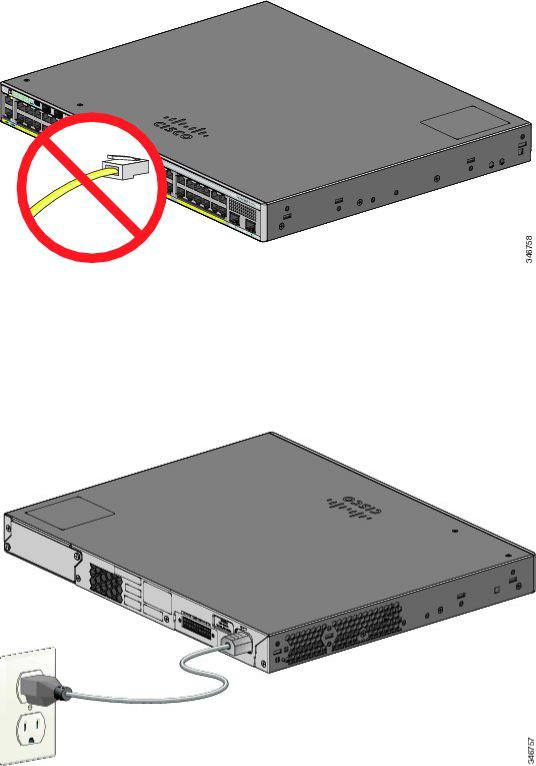
Step 1 Make sure that nothing is connected to the switch.
3
Step 2 During Express Setup, the switch acts as a DHCP server. If your PC has a static IP address, temporarily configure your PC settings to use DHCP before proceeding to the next step.
Note Write down the static IP address. You will need this IP address in Step 12.
Step 3 Power the switch by connecting the AC power cord to the switch power supply and to a grounded AC outlet.
For information about installing the power supplies in the Catalyst 2960-XR switches, see the hardware guide at http:// www.cisco.com/go/cat2960xr_docs
Step 4 Observe the POST results.
4

Approximately 30 seconds after the switch powers on, it begins the power-on self-test (POST), which can take up to 5 minutes to complete.
During POST, the SYST (system) LED blinks green. When POST is complete, the SYST LED turns solid green. The MAST (master) LED is green if the switch is acting as the stack master.
Before going to the next step, wait until POST is complete.
Note If the SYST LED does not turn solid green, or turns amber, the switch failed the POST. Contact your Cisco representative or reseller.
Step 5 Press the Mode button when the SYST, MAST, and STAT LED turn green, hold the Mode button until all the LEDs next to the Mode button turn green.
You might need to hold the button for more than 3 seconds.
The switch is now in Express Setup mode.
Note If the LEDs next to the Mode button blink when you press the button, release it. Blinking LEDs indicate that the switch is already configured and cannot go into Express Setup mode. See Resetting the Switch, on page 21.
Step 6 Connect a Category 5 or 6 Ethernet cable to a port:
•Any 10/100/1000 or 10/100/1000 PoE+ Ethernet port
•The RJ-45 Ethernet management port
Connect the other end of the cable to the Ethernet port on your PC.
Wait until the port LEDs on the switch and your PC or laptop are green or blinking green. Green LEDs indicate a successful connection.
5
Note If the port LEDs do not turn green after about 30 seconds, make sure that:
•You connected the Ethernet cable to one of the downlink switch ports (not to the console port).
•You are using an undamaged Category 5 or 6 Ethernet cable.
•The other device is on.
Step 7 Start a browser session on the PC, and enter the IP address https://10.0.0.1. When prompted, enter the default password, cisco.
Note The switch ignores text in the username field.
The Express Setup window appears. If the Express Setup window does not appear, make sure that any pop-up blockers or proxy settings on your browser are disabled and that any wireless client is disabled on your PC or laptop.
Step 8 Enter this information in the Network Settings fields:
Note All entries must be in English letters.
•In the Management Interface (VLAN ID) field, the default is 1. We recommend that you use the default VLAN value. During Express Setup, VLAN 1 is the only VLAN on the switch. Enter a new VLAN ID only if you want to change the management interface through which you manage the switch. The VLAN ID range is 1 to 1001.
•In the IP Address field, enter the switch IP address.
•In the Subnet Mask field, click the drop-down arrow, and select a subnet mask.
•In the Default Gateway field, enter the IP address for the default gateway (router).
•In the Switch Password field, enter your password . The password can be from 2 to 25 alphanumeric characters, can start with a number, is case sensitive, allows embedded spaces, but does not allow spaces at the beginning or end. In the Confirm Switch Password field, enter your password again.
Note You must change the password from the default password, cisco.
(Optional) Enter this information in the Ethernet Management Port Settings fields:
•In the IP Address field, enter the IP address of the Ethernet management port.
•In the Subnet Mask field, click the drop-down arrow, and select an IP Subnet Mask field, click the drop-down arrow, and select and IP Subnet Mask.
Step 9 Enter information in the optional fields.
You can enter other administrative settings in the Express Setup window. For example, the optional administrative settings identify and synchronize the switch for enhanced management. The switch clock is automatically synchronized with the network clock by using NTP. You can manually set the system clock settings if the switch should have different time settings.
Step 10 Click Submit to save your changes and to complete the initial setup.
After you click Submit:
• The switch is configured and exits Express Setup mode.
6

•The browser displays a warning message and tries to connect with the earlier switch IP address. Typically, connectivity between the PC and the switch is lost because the configured switch IP address is in a different subnet from the IP address on the PC.
For more information about Express Setup fields, see the online help for the Express Setup window.
Step 11 Disconnect the switch from the PC, and install the switch in your network.
Step 12 If you changed the static IP address on your PC in Step 2, change it to the previously configured static IP address.
Step 13 You can now manage the switch by using Cisco Network Assistant, Device Manager, or both. See Managing the Switch for information about configuring and managing the switch. We strongly recommend that you download Cisco Network Assistant from Cisco.com and use it to manage the switch.
You can display Device Manager by following these steps:
•Start a web browser on your PC or laptop.
•Enter the switch IP address, username, and password in the web browser, and press Enter. The Device Manager page appears.
If Device Manager does not appear:
◦Confirm that the port LED for the switch port connected to your network is green.
◦Confirm that the PC or laptop you are using to access the switch has network connectivity by connecting to a well-known web server in your network. If there is no network connection, troubleshoot the network settings on the PC or laptop.
◦Make sure that the switch IP address in the browser is correct.
◦If the switch IP address in the browser is correct, the switch interface LED is green, and the PC or laptop has network connectivity, continue troubleshooting by reconnecting the PC or laptop to the switch. Configure a static IP address on the PC or laptop that is in the same subnet as the switch IP address. For example:
•If your switch IP address is 172.20.20.85 and your PC or laptop IP address is 172.20.20.84, both devices are in the same network.
•If your switch IP address is 172.20.20.85 and your PC or laptop IP address is 10.0.0.2, the devices are in different networks and cannot communicate directly.
◦When the LED on the switch port connected to the PC or laptop is green, reenter the IP address of the switch in a web browser to display Device Manager. When Device Manager appears, you can continue with the switch configuration.
Managing the Switch
After completing Express Setup and installing the switch in your network, you can use one of these options for further configuration.
7

Using Device Manager
ThesimplestwaytomanagetheswitchisbyusingDeviceManagerintheswitchmemory. Thiswebinterfaceoffersquickconfiguration and monitoring. You can access Device Manager from anywhere in your network through a web browser.
Procedure
Step 1 Launch a web browser on your PC or workstation.
Step 2 Enter the switch IP address in the web browser, and press Enter. The Device Manager page appears.
Step 3 Use Device Manager to perform basic switch configuration and monitoring. See the Device Manager online help for more information.
Step 4 For a more advanced configuration, download and run Cisco Network Assistant, which is described in the next section.
Using Cisco Network Assistant
Cisco Network Assistant is a software program that you download from Cisco.com and run on your PC. It offers advanced options for configuring and monitoring multiple devices, including switches, switch clusters, switch stacks, routers, and access points. Cisco Network Assistant is free—there is no charge to download, install, or use it.
Go to this URL: http://www.cisco.com/en/US/products/ps5931/index.html
Procedure
Step 1 Click the Download Software link, and select the version that you want to download.
You must be a registered Cisco.com user, but you need no other access privileges.
Step 2 Find the Network Assistant installer.
Step 3 Download the Network Assistant installer and run it. (You can run it directly from the Web if your browser offers this choice.)
Step 4 When you run the installer, follow the displayed instructions. In the final panel, click Finish to complete the Network Assistant installation.
See the Network Assistant online help and the getting started guide for more information.
Using the Command-Line Interface
You can enter Cisco IOS commands and parameters through the CLI. Access the CLI by using one of these options.
8
Loading...