


 Loading...
Cisco Smart Install Configuration Guide
December 10, 2014
Cisco Systems, Inc.
www.cisco.com
Cisco has more than 200 offices worldwide. Addresses, phone numbers, and fax numbers are listed on the Cisco website at www.cisco.com/go/offices.
Text Part Number: OL-28027-01
THE SPECIFICATIONS AND INFORMATION REGARDING THE PRODUCTS IN THIS MANUAL ARE SUBJECT TO CHANGE WITHOUT NOTICE. ALL STATEMENTS, INFORMATION, AND RECOMMENDATIONS IN THIS MANUAL ARE BELIEVED TO BE ACCURATE BUT ARE PRESENTED WITHOUT WARRANTY OF ANY KIND, EXPRESS OR IMPLIED. USERS MUST TAKE FULL RESPONSIBILITY FOR THEIR APPLICATION OF ANY PRODUCTS.
THE SOFTWARE LICENSE AND LIMITED WARRANTY FOR THE ACCOMPANYING PRODUCT ARE SET FORTH IN THE INFORMATION PACKET THAT SHIPPED WITH THE PRODUCT AND ARE INCORPORATED HEREIN BY THIS REFERENCE. IF YOU ARE UNABLE TO LOCATE THE SOFTWARE LICENSE OR LIMITED WARRANTY, CONTACT YOUR CISCO REPRESENTATIVE FOR A COPY.
The Cisco implementation of TCP header compression is an adaptation of a program developed by the University of California, Berkeley (UCB) as part of UCB’s public domain version of the UNIX operating system. All rights reserved. Copyright © 1981, Regents of the University of California.
NOTWITHSTANDING ANY OTHER WARRANTY HEREIN, ALL DOCUMENT FILES AND SOFTWARE OF THESE SUPPLIERS ARE PROVIDED “AS IS” WITH ALL FAULTS. CISCO AND THE ABOVE-NAMED SUPPLIERS DISCLAIM ALL WARRANTIES, EXPRESSED OR IMPLIED, INCLUDING, WITHOUT LIMITATION, THOSE OF MERCHANTABILITY, FITNESS FOR A PARTICULAR PURPOSE AND NONINFRINGEMENT OR ARISING FROM A COURSE OF DEALING, USAGE, OR TRADE PRACTICE.
IN NO EVENT SHALL CISCO OR ITS SUPPLIERS BE LIABLE FOR ANY INDIRECT, SPECIAL, CONSEQUENTIAL, OR INCIDENTAL DAMAGES, INCLUDING, WITHOUT LIMITATION, LOST PROFITS OR LOSS OR DAMAGE TO DATA ARISING OUT OF THE USE OR INABILITY TO USE THIS MANUAL, EVEN IF CISCO OR ITS SUPPLIERS HAVE BEEN ADVISED OF THE POSSIBILITY OF SUCH DAMAGES.
Cisco and the Cisco logo are trademarks or registered trademarks of Cisco and/or its affiliates in the U.S. and other countries. To view a list of Cisco trademarks, go to this URL: www.cisco.com/go/trademarks. Third-party trademarks mentioned are the property of their respective owners. The use of the word partner does not imply a partnership relationship between Cisco and any other company. (1110R)
Any Internet Protocol (IP) addresses and phone numbers used in this document are not intended to be actual addresses and phone numbers. Any examples, command display output, network topology diagrams, and other figures included in the document are shown for illustrative purposes only. Any use of actual IP addresses or phone numbers in illustrative content is unintentional and coincidental.
Cisco Smart Install Configuration Guide
© 2009-2014 Cisco Systems, Inc. All rights reserved.

Contents
C O N T E N T S
|
Introduction 1-1 |
|
|
|
|
|
|
|
|
|
|
|
|
|
Smart Install Director |
|
1-3 |
|
|
|
|
|
|
|
|
|
|
|
Image List File |
1-5 |
|
|
|
|
|
|
|
|
|
|
|
|
Configuration Files |
|
1-6 |
|
|
|
|
|
|
|
|
|
|
|
Smart Install Clients |
1-6 |
|
|
|
|
|
|
|
|
|
|
|
|
Smart Install Groups |
|
1-9 |
|
|
|
|
|
|
|
|
|
|
|
DHCP and Smart Install |
1-10 |
|
|
|
|
|
|
|
|
|
|
|
|
Adding a Client Switch to the Network |
|
1-11 |
|
|
|
|
|
|
|
|||
|
Backing Up the Client Configuration |
1-12 |
|
|
|
|
|
|
|
||||
|
Replacing a Client Switch |
|
1-12 |
|
|
|
|
|
|
|
|
|
|
|
Using a Join Window |
|
1-13 |
|
|
|
|
|
|
|
|
|
|
|
Configuring Join Window Mode |
1-14 |
|
|
|
|
|
|
|
||||
|
Updating Client Switches |
|
1-15 |
|
|
|
|
|
|
|
|
|
|
|
Zero-Touch Installation |
|
1-15 |
|
|
|
|
|
|
|
|
|
|
|
Connecting to a Client Switch |
1-16 |
|
|
|
|
|
|
|
|
|
||
|
Configuration Guidelines and Recommendations |
2-1 |
|
|
|
|
|
|
|||||
|
DHCP Configuration Guidelines |
2-4 |
|
|
|
|
|
|
|
|
|||
|
Configuring the DHCP Server |
2-4 |
|
|
|
|
|
|
|
|
|
||
|
Configuring the Director as the DHCP Server |
2-5 |
|
|
|
|
|
|
|||||
|
Configuring Another Device as DHCP Server |
2-6 |
|
|
|
|
|
|
|||||
|
Configuring the TFTP Server |
|
2-8 |
|
|
|
|
|
|
|
|
|
|
|
Establishing a Remote Client Session |
2-8 |
|
|
|
|
|
|
|
||||
|
Configuring a Network with Single or Mixed Switch Types |
2-9 |
|
|
|
|
|||||||
|
Configuring a Network That Includes a Single Switch Type |
2-9 |
|
|
|
||||||||
|
Using Built-In Groups to Configure a Mixed Network with Two Switch Types 2-12 |
||||||||||||
|
Updating On-Demand to a New Image or Configuration |
2-16 |
|
|
|
|
|||||||
|
Configuring Custom Group Based on Connectivity |
2-19 |
|
|
|
|
|||||||
|
Configuring a Custom Group Based on MAC Address |
2-21 |
|
|
|
|
|||||||
|
Configuring a Custom Group Based on a Stack Number |
2-23 |
|
|
|
||||||||
|
Custom Group Based on Product ID |
2-26 |
|
|
|
|
|
|
|
||||
|
Managing Client Configuration Files |
2-28 |
|
|
|
|
|
|
|
||||
|
Backing Up Files after Loss of Connection |
2-28 |
|
|
|
|
|
|
|||||
|
Extracting and Displaying Tar Files |
2-28 |
|
|
|
|
|
|
|
||||
|
Other Configuration Options |
|
2-29 |
|
|
|
|
|
|
|
|
|
|
|
Disabling Smart Install on a Device |
2-29 |
|
|
|
|
|
|
|
||||
|
Managing File Downloads on Clients |
2-29 |
|
|
|
|
|
|
|
||||
|
Download Management for Non-Smart Install Clients |
2-29 |
|
|
|
||||||||
|
|
|
|
|
|
|
|
Cisco Smart Install Configuration Guide |
|
|
|
||
|
|
|
|
|
|
|
|
|
|||||
|
|
|
|
|
|
|
|
|
|
|
|
|
|
|
OL-28027-01 |
|
|
|
|
|
|
|
|
|
|
iii |
|
|
|
|
|
|
|
|
|
|
|
|
|
||

Contents
|
|
|
Download Management for Smart Install Clients |
2-29 |
|
|
||||||||
|
|
|
Configuring a Client Hostname Prefix |
2-30 |
|
|
|
|
||||||
|
|
|
Configuring Additional Smart Install Management VLANs 2-30 |
|
|
|||||||||
|
|
|
Configuring a Group for Standalone Catalyst 4500 Series Switch |
2-31 |
|
|||||||||
|
|
|
Restrictions and Guidelines |
2-32 |
|
|
|
|
|
|
||||
|
|
|
The Procedure |
|
2-32 |
|
|
|
|
|
|
|
|
|
|
|
|
On-Demand Upgrade for Catalyst 4500 Series Switch IBC |
2-36 |
|
|||||||||
|
|
|
Support for Post-install Operations |
2-37 |
|
|
|
|
|
|||||
|
|
|
Configure a Script for Default Mode |
2-38 |
|
|
|
|
||||||
|
|
|
Configure a Script for the Built-in Group Mode |
2-39 |
|
|
||||||||
|
|
|
Configure a Script for Custom Group Mode 2-40 |
|
|
|
||||||||
|
|
|
Smart Install Configuration Examples |
2-41 |
|
|
|
|
|
|||||
|
|
|
Director as the TFTP Server |
2-41 |
|
|
|
|
|
|
|
|||
|
|
|
Before Configuring the Director |
2-41 |
|
|
|
|
|
|||||
|
|
|
Configure a Director |
2-42 |
|
|
|
|
|
|
|
|||
|
|
|
Third-Party, Non-Cisco IOS Device as the TFTP Server |
2-43 |
|
|
||||||||
|
|
|
Before Configuring the Director |
2-43 |
|
|
|
|
|
|||||
|
|
|
Configure the Director |
2-43 |
|
|
|
|
|
|
|
|||
|
|
|
Information about SMI Proxy |
4-1 |
|
|
|
|
|
|
|
|||
|
|
|
How SMI Proxy Interacts with Smart Install Devices and the PnP Agent 4-2 |
|||||||||||
|
|
|
How SMI Clients and Directors Communicate |
4-2 |
|
|
|
|||||||
|
|
|
How SMI Proxy and PnP Agent Communicate |
4-2 |
|
|
|
|||||||
|
|
|
SMI Proxy and Tailored Configuration Files |
4-3 |
|
|
|
|
||||||
|
|
|
SMI Proxy Database |
4-3 |
|
|
|
|
|
|
|
|
||
|
|
|
Enabling Proxy on the Device |
4-4 |
|
|
|
|
|
|
|
|||
|
|
|
Unsupported Services |
4-5 |
|
|
|
|
|
|
|
|
|
|
|
|
|
Guidelines and Restrictions |
4-6 |
|
|
|
|
|
|
|
|
||
|
|
|
SMI Proxy CLI Commands |
4-7 |
|
|
|
|
|
|
|
|
||
4-19 |
|
|
|
|
|
|
|
|
|
|
|
|||
|
|
|
SNMP MIBs 5-1 |
|
|
|
|
|
|
|
|
|
|
|
|
|
|
Cisco Smart Install MIB |
5-1 |
|
|
|
|
|
|
|
|
||
|
|
|
Downloading and Working with MIBs |
5-2 |
|
|
|
|
|
|||||
|
|
|
Guidelines for Working with MIBs |
5-2 |
|
|
|
|
||||||
|
|
|
Downloading MIBs |
5-3 |
|
|
|
|
|
|
|
|
||
|
|
|
System Messages 5-3 |
|
|
|
|
|
|
|
|
|
|
|
|
|
|
How to Read System Messages |
5-3 |
|
|
|
|
|
|
||||
|
|
|
Error Message Traceback Reports |
5-4 |
|
|
|
|
|
|||||
|
|
|
Output Interpreter |
5-4 |
|
|
|
|
|
|
|
|
||
|
|
|
Bug Toolkit |
5-5 |
|
|
|
|
|
|
|
|
|
|
|
|
|
Cisco Smart Install Configuration Guide |
|
|
|
|
|
|
|
|
|
|
|
|
|
|
|
|
|
|
|
|
|
|
|
|
|
|
|
|
|
|
|
|
|
|
|
|
|
|
|
|
|
|
iv |
|
|
|
|
|
|
|
|
|
|
|
OL-28027-01 |
|
|
|
|
|
|
|
|
|
|
|
|
|
|
||

Contents
Smart Install System Messages 5-5
Minimum Cisco IOS Release for Major Features C-1
Cisco Smart Install Configuration Guide
|
OL-28027-01 |
v |
|

Contents
Cisco Smart Install Configuration Guide
|
vi |
OL-28027-01 |
|
|
|

Preface
This guide provides procedures for installing and using Smart Install and using the related commands. For information about other standard Cisco IOS Release 12.2 commands or Cisco IOS Release 15.0, see the Cisco IOS documentation set available from the Cisco.com home page at Products & Services > Cisco IOS and NX OS Software> Cisco IOS.
This guide does not describe system messages you might encounter or how to install your device. For more information, see the system message guide and the hardware installation guide for the device.
For documentation updates, and other late information, see the release notes for the specific device for this release.
Conventions
This publication uses these conventions to convey instructions and information:
Command descriptions use these conventions:
•Commands and keywords are in boldface text.
•Arguments for which you supply values are in italic.
•Square brackets ([ ]) mean optional elements.
•Braces ({ }) group required choices, and vertical bars ( | ) separate the alternative elements.
•Braces and vertical bars within square brackets ([{ | }]) mean a required choice within an optional element.
Interactive examples use these conventions:
•Terminal sessions and system displays are in screen font.
•Information you enter is in boldface screen font.
•Nonprinting characters, such as passwords or tabs, are in angle brackets (< >). Notes and cautions use these conventions and symbols:
Note Means reader take note. Notes contain helpful suggestions or references to materials not contained in this manual.
Cisco Smart Install Configuration Guide
1

Caution Means reader be careful. In this situation, you might do something that could result in equipment damage or loss of data.
Related Publications
•Catalyst 6500 Supervisor Engine 2T-10GE
http://www.cisco.com/en/US/products/hw/switches/ps708/tsd_products_support_series_home.htm l
•Catalyst 4500
http://www.cisco.com/en/US/products/hw/switches/ps4324/tsd_products_support_series_home.ht ml
•Catalyst 3850 http://www.cisco.com/en/US/products/ps12686/tsd_products_support_series_home.html
•Catalyst 3750-X http://www.cisco.com/en/US/products/ps10745/tsd_products_support_series_home.html
•Catalyst 3750-E http://www.cisco.com/en/US/products/ps7077/tsd_products_support_series_home.html
•Catalyst 3750
http://www.cisco.com/en/US/products/hw/switches/ps5023/tsd_products_support_series_home.ht ml
•Catalyst 3650
http://preview.cisco.com/en/US/products/ps13133/products_installation_and_configuration_guides _list.html
•Catalyst 3560
http://www.cisco.com/en/US/products/hw/switches/ps5528/tsd_products_support_series_home.ht ml
•Catalyst 3560-E http://www.cisco.com/en/US/products/ps7078/tsd_products_support_series_home.html
•Catalyst 3560-X http://www.cisco.com/en/US/products/ps10744/tsd_products_support_series_home.html
•Catalyst 2975 http://www.cisco.com/en/US/products/ps10081/tsd_products_support_series_home.html
•Catalyst 2960, Catalyst 2960-S, and Catalyst 2960-SF http://www.cisco.com/en/US/products/ps6406/tsd_products_support_series_home.html
•Catalyst 2960-X http://www.cisco.com/en/US/products/ps12995/tsd_products_support_series_home.html
•Catalyst 2960-XR http://www.cisco.com/en/US/products/ps13078/tsd_products_support_series_home.html
Cisco Smart Install Configuration Guide
2

•IE 2000
http://www.cisco.com/c/en/us/support/switches/industrial-ethernet-2000-series-switches/tsd-produ cts-support-series-home.html
•IE3000
http://www.cisco.com/c/en/us/support/switches/industrial-ethernet-3000-series-switches/tsd-produ cts-support-series-home.html
•IE3010
http://www.cisco.com/c/en/us/support/switches/industrial-ethernet-3010-series-switches/tsd-produ cts-support-series-home.html
•EtherSwitch Network Modules
https://www.cisco.com/en/US/docs/ios/lanswitch/configuration/guide/lsw_enet_switch_net_extern al_docbase_0900e4b18090920b_4container_external_docbase_0900e4b18096f791.html
Obtaining Documentation, Obtaining Support, and Security
Guidelines
For information on obtaining documentation, submitting a service request, and gathering additional information, see the monthly What’s New in Cisco Product Documentation, which also lists all new and revised Cisco technical documentation, at:
http://www.cisco.com/en/US/docs/general/whatsnew/whatsnew.html
Subscribe to the What’s New in Cisco Product Documentation as a Really Simple Syndication (RSS) feed and set content to be delivered directly to your desktop using a reader application. The RSS feeds are a free service and Cisco currently supports RSS version 2.0.
Cisco Smart Install Configuration Guide
3

Cisco Smart Install Configuration Guide
4
C H A P T E R 1
Smart Install Overview
•Introduction, page 1-1
•DHCP and Smart Install, page 1-10
•Adding a Client Switch to the Network, page 1-11
•Backing Up the Client Configuration, page 1-12
•Updating Client Switches, page 1-15
•Connecting to a Client Switch, page 1-16
Introduction
Smart Install is a plug-and-play configuration and image-management feature that provides zero-touch deployment for new switches. You can ship a switch to a location, place it in the network and power it on with no configuration required on the device.
A network using Smart Install includes a group of networking devices, known as clients, that are served by a common Layer 3 switch or router that acts as a director. In a Smart Install network, you can use the Zero-Touch Installation process to install new access layer switches into the network without any assistance from the network administrator. The director provides a single management point for images and configuration of client switches. When a client switch is first installed into the network, the director automatically detects the new switch, and identifies the correct Cisco IOS image and the configuration file for downloading. It can allocate an IP address and host name to a client. If a standalone switch in the network is replaced by another switch of the same SKU (a switch with the same product ID), it automatically gets the same configuration and image as the previous one. The director can also perform on-demand configuration and software image updates of a switch or a group of switches in the network.
Zero-touch updates also take place on preconfigured switches after you have entered the write erase and reload privileged EXEC commands to clear the configuration.
Caution If you touch the console keyboard during a zero-touch update and attempt to enter a command or a return on the switch, the auto install and Smart Install processes stop. To recover and restart the process, at the system prompt, enter the write erase and reload commands on the client and restart the process.
The director can act as a DHCP and TFTP server and can store the configuration and image files. These files can also be stored on a third-party TFTP server for the director to use. The client can download the image and configuration files from the director TFTP server or from a remote server.
Cisco Smart Install Configuration Guide
1-1
Chapter 1 Smart Install Overview
Introduction
Note Switches running releases earlier than 12.2(52)SE are not Smart Install capable, but they can be Smart Install clients if they support the archive download-sw privileged EXEC command. Smart Install clients can be Layer 2 or Layer 3 switches. Switches running Cisco IOS Releases 3.2(0)SE and later, and 15.0 (2)SE and later, 3.6.(0)E, and 15.2.(2)E support Smart Install.
See Appendix A, “Supported Devices for Smart Install” for a list of supported routers and switches, the roles they can play (client or director), and the required software releases.
In a typical Smart Install network, a client switch uses DHCP to get an IP address and the director snoops DHCP messages. For a client to participate in Smart Install zero-touch update, it must use DHCP, and all DHCP communication must pass through the director so that it can snoop all DHCP packets from clients. The most automatic operation is when all switches in the Smart Install network use DHCP and are Smart Install capable. However, any client switch that supports the archive download-sw privileged EXEC command to download a software image can be used in a zero-touch Smart Install network. Cisco IOS Release 3.2(0)SE and later, support software install.
Note A Smart Install network can have only one director.
A client switch can participate in Smart Install even if it is not directly connected to the director. The
Smart Install network supports up to seven hops. Intermediate switches or clients connected to the director through an intermediate switch in a multihop environment can be, but are not necessarily
Smart Install capable, provided the management VLAN is set to default VLAN 1.
If you use a VLAN other than vlan 1 for management, then the intermediate switch must be Smart Install capable switch.
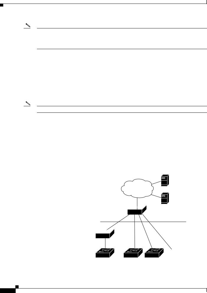
Figure 1-1 shows a Smart Install network with external DHCP and TFTP servers. There can be only one director amongst TFTP servers in any Smart Install network. The director can also serve as the DHCP and TFTP server.
Figure 1-1 Typical Smart Install Network Diagram
DHCP server
TFTP server
Director 
Aggregation layer
Access layer
Intermediate 
switch
 206531
Client switches
Cisco Smart Install Configuration Guide
1-2

Chapter 1 Smart Install Overview
Introduction
A Smart Install network can be:
•A network where all client switches are of the same product ID (PID), for example, WS-2960S-48FPS-L. In this case, you can identify a default image and a seed or basic configuration to use on all client switches.
•A network that includes switches with different PIDs. In these networks, you can configure switch groups and specify that the same images and seed configuration files are applied to all switches in the group. A group can be based on a predefined PID, or you can create groups based on product ID, MAC address, switch stack number, MAC address, or client switch connectivity to a specific upstream neighbor. When switches in a group are replaced by another switch with the same product ID, the replacement switch receives the same configuration and image.
After a switch has an image and basic configuration, you can configure specific features on individual switches and save the configuration to the startup configuration file.
Switches participating in Smart Install zero-touch updates must use DHCP to obtain their IP addresses. DHCP options are used to send:
•Image filename and location
•TFTP server IP address
•Hostname
•Configuration filename
•Director IP address to the other switches
When a director is configured and a client joins the Smart Install network, Smart Install is automatically enabled on these devices. Beginning with Cisco IOS Release 12.2(58)SE, XE 3.4SG, 15.1(2)SG, 15.1(1)SY, 15.0(2)SE, 3.2(0)SE and later, 3.6.(0)E, or 15.2.(2)E, you can disable Smart Install on a device and also shut down its Smart Install TCP ports by entering the no vstack global configuration command on the client or director. When Smart Install is disabled on a device, any Smart Install configuration on it remains in the running configuration but does not take effect while Smart Install is disabled. To reenable Smart Install on the device, enter the vstack global configuration command.
These sections include more detailed information on Smart Install components:
•Smart Install Director, page 1-3
•Smart Install Clients, page 1-6
•Smart Install Groups, page 1-9
Smart Install Director
The director in a Smart Install network must be a Layer 3 switch running Cisco IOS Release 12.2(52)SE or later, XE 3.4SG, 15.1(2)SG, 15.0(2)SE or later, 15.1(1)SY or later, 3.2(0)SE or later, or a router running Cisco IOS Release 15.1(3)T or later. See Appendix A, “Supported Devices for Smart Install” for a list of routers and switches that can perform the role of Smart Install director.
Note IE2000 IE3000, and IE3010 support Director with Cisco IOS Release 15.2(2)E.
To configure a device as director, enter the IP address of one of its Layer 3 interfaces in the vstack director ip_ address global configuration command and enable it as director by entering the vstack basic command.
Cisco Smart Install Configuration Guide
1-3

Chapter 1 Smart Install Overview
Introduction
Note
Note
Note
If you have entered the no vstack global configuration command to disable Smart Install on a device, the vstack director ip_ address and vstack basic global configuration commands are not allowed on the device. To reenable Smart Install on a device, enter the vstack global configuration command.
When a device is configured as director, The VLAN on which the DHCP snooping is automatically enabled becomes VLAN 1 by default. The director begins building the director database in VLAN 1. To specify another VLAN for Smart Install management, you can use the vstack startup-vlan global configuration command. Depending on the VLAN that is specified in the command, DHCP snooping is enabled on that VLAN so that the director can identify new switches that are connected to the network, known as non-VLAN 1 switches.
The database lists the client devices in the Smart Install network and includes this information:
•Type of switch (PID) for all switches, including switches in a stack
•MAC addresses for all switches, including switches in a stack
•IP address of the switch or stack
•Hostname
•Network topology including neighbors interfacing with the switch
•Serial number (only Smart Install capable switches)
When the director is a switch, DHCP snooping is enabled on VLAN 1 by default. It is also enabled on other Smart Install management VLANs that are configured by entering the vstack vlan vlan-range global configuration command. You can use the vstack startup-vlan global configuration command to specify another VLAN that should be used for Smart Install management. Cisco IOS Releases 15.1(1)SY, 15.0(2)SE or later, 15.1(2)SG, 3.6.(0)E, 15.2.(2)E, and Cisco IOS XE 3.4SG support non-VLAN1 management and provide the ability to discover the client switches available on non-VLAN1.
In a Smart Install network that uses DHCP to assign IP addresses, you only need to configure the director. Client switches do not require any configuration. Although you can enter command-line interface commands on clients, configuration commands do not take effect unless the switch assumes the role of director.
You can configure the vstack commands in client mode. but this is effective only when the switch is converted to a director.
There can be only one director for a set of clients and you cannot configure a backup director. If the director fails:
•Director database must be rebuilt.
•Any update being performed for a non-Smart Install-capable switch might fail.
•The accumulated download status is lost.
•A configuration backup might not occur before the director restarts.
The director can change status and become a client switch if:
•The director interface that has the director IP address shuts down.
•The director interface that has the director IP address is deleted.
Cisco Smart Install Configuration Guide
1-4

Chapter 1 Smart Install Overview
Introduction
• The director IP address is changed.
If the director becomes a client, DHCP snooping is disabled, and the director database is no longer used.
If the director IP address is provided by DHCP and you configure a different director IP address on a client switch, the client is longer part of the director’s Smart Install network.
Smart Install relies on a TFTP server to store image and configuration files. The TFTP server can be an external device, or the director can act as a TFTP server. If the director is the TFTP server, the available flash file space on the director must be adequate to accommodate the client Cisco IOS image and configuration files. See the “Configuring the TFTP Server” section on page 2-8.
In a Smart Install network using DHCP, the DHCP server can be an external device or the director can act as the DHCP server. See the “Configuring the DHCP Server” section on page 2-4. The director snoops all DHCP packets that pass through it on VLANs that are configured as Smart Install management VLANs. All network DHCP packets from intermediate or client switches or from an external DHCP server must pass through the director. The director must be able to snoop all DHCP packets from clients.
Note Smart Install options in the DCHP offer are option 125, suboption 5 (the image list file), option 125 sub-option 16 (the director IP address), and option 67 (the configuration file).
The director builds a topology director database for the network by collecting information from the network Smart Install switches. The director uses the database:
•To assign a configuration file and image to a client.
•As a reference to obtain the PID, the image name, and the configuration file for an on-demand update of network switches.
The director periodically updates the director database based on CDP updates that it receives from neighbor switches and from Smart Install messages sent to the director by Smart Install capable clients. The updates contain information about the client neighbors.
Image List File
An image list identifies the images to be loaded on the client. The image list file is the file that contains the correct image name for the client. When the director is the TFTP server, this file is stored in flash memory. Otherwise, it is stored in a remote, third-party TFTP server.
•When the file is stored in the director, the prefix for the image list is flash://, usbflash0://, bootflash://, bootdisk://, or disk0:// based on the appropriate file systems available on the switch.
•When the file is stored in a remote TFTP server, the prefix is tftp://ip_address/image.tar.
Note In Catalyst Switches 3850 and 3650, the image is a bundled with .bin extension.
Images must be stored either on the director or on the third-party TFTP server.
For a standalone switch, the image list file contains a single image. For a stack, the image list contains images for all members of the stack, which could be the same image or different images. For a switch stack, the director creates the image list file after the user specifies the tar file for each switch in the stack.
Starting with Cisco IOS Release 12.2(55)SE or later,15.1(1)SY, 15.0(2)SE and later, 3.2(0)SE and later, XE 3.4SG, 15.1(2)SG, 3.6.(0)E, and 15.2.(2)E, when the user specifies the tar file for each switch, the director automatically creates the imagelist file.
Cisco Smart Install Configuration Guide
1-5

Chapter 1 Smart Install Overview
Introduction
When an external TFTP server is used, the director writes the image list file to the TFTP server. It is recommended that the TFTP server permit the director to write the image list files to the TFTP Server. If the director does not have permission to write to the file system of the TFTP server, the director logs the failure in the system log. You can create the image list files and put them on the TFTP server manually if the director fails to do so automatically; you cannot fix the issue that prevents the director from writing to the TFTP server.
Note The upgrade process is initialized even when the imagelist file is copied manually, but the director tries to copy the image list file to the TFTP server and the failure system log is displayed periodically.
Configuration Files
The director manages these configuration files:
•Startup configuration—The configuration that a client uses when it boots.
•Seed configuration—A configuration on the director that is the basis for the client startup configuration.
•Backup configuration—An exact copy of a client startup configuration stored in the director.
Smart Install Clients
Client switches have a direct or indirect connection to the director so that they can receive image and configuration downloads from it. A switch becomes a Smart Install client when either director or when the director IP address is configured on the switch manually. Client switches use the director database for image and configuration downloads and receive the image and configuration files from the Smart Install TFTP server.
A client switch can be an intermediate switch connected to another client switch. A client can be a standalone switch or a switch stack.
•Director can download images and configuration of clients that are not Smart Install. However, such clients are entered into the director database only if they are connected to a Smart Install capable switch. The director can telnet to the client switch and use the archive download-sw privileged EXEC command to download software to the switch. The director must know the client switch password to perform the download.
•Smart Install capable switches can communicate directly with the director to update switch information, can have images and configuration downloaded, and can be managed by the director. A Smart Install capable client with the director IP address and connectivity to the director sends switch and neighbor information to the director by using the Smart Install protocol.
Note Switches running Cisco IOS XE Releases 3.2(0)SE and later, 3.6.(0)E, and 15.2.(2)E support software install.
All switches in the network with “network” connectivity to the director can be clients, whether or not they are Smart Install capable. A client switch needs an IP address for management communication and the director must be able to communicate with that IP address. Client switch IP addresses are assigned by DHCP or statically configured.
Cisco Smart Install Configuration Guide
1-6

Chapter 1 Smart Install Overview
Introduction
Smart Install capable clients send switch and neighbor information to the connected director for the director database. Client switches that are not Smart Install capable or that are not connected to a Smart Install capable switch are not entered into the director database. In a multihop topology, for the director to get the complete topology overview, any client switch upstream of a group of clients must be Smart Install capable. Clients not in the director database can get an on-demand update, but they cannot get a zero-touch or group update.
Figure 1-2 shows some possible ways that clients can be interconnected in a network. Table 1-1 and Table 1-2 shows the director database knowledge of each client and the type of update that is supported.
Note The topology shown in Figure 1-2 does not represent a typical Smart Install topology but is used to demonstrate possible types of client interconnections.
Figure 1-2 Possible Interconnections of Smart Install Clients
Director
Client 1 |
Client 3 |
Client 5 |
Client 7 |
Client 2 |
Client 4 |
Client 6 |
Client 8 |
Smart Install capable switch
Switch running an image earlier than Cisco IOS Release 12.2(52)SE
Smart Install capable switch supporting non-VLAN management
276559
Note The Cisco IOS releases12.2(52)SE or later, XE 3.4SG, 15.1(2)SG, 15.1(1)SY and later, 15.0(2)SE and later, and 3.2(0)SE and later, support the director role. The Cisco IOS releases 15.0(2)SE, 15.1(1)SY, 15.1(2)SG, XE 3.4SG, 15.0(2)EX, 15.0(2)EX1, 3.6.(0)E, and 15.2.(2)E are Smart Install capable switches, supporting non-VLAN 1 management and providing the ability to discover the client switches available on non-VLAN 1.
Table 1-1 shows the switches that are in the director database and how the director obtained the information. When a client is a single hop from the director, the client uses CDP to send the director information about itself. When a client is a Smart Install capable switch, it sends information to the director about itself and its neighbors.
Cisco Smart Install Configuration Guide
1-7

Chapter 1 Smart Install Overview
Introduction
Table 1-1 |
Director Database Contents of Client Switches |
||
|
|
|
|
|
|
In Director |
|
Client Switch |
|
Database? |
Source of Database Information |
|
|
|
|
Client 1 |
|
Yes |
Learned from CDP and from Smart Install. The client also sends |
|
|
|
information about its neighbor (Client 2). |
|
|
|
|
Client 2 |
|
Yes |
Information received from Client 1. |
|
|
|
|
Client 3 |
|
Yes |
Learned from CDP. |
|
|
|
|
Client 4 |
|
No |
No information available. The client is not an immediate neighbor |
|
|
|
of the director or another Smart Install switch. |
|
|
|
|
Client 5 |
|
Yes |
Learned from CDP. |
|
|
|
|
Client 6 |
|
No |
No information available. The client is not an immediate neighbor |
|
|
|
of the director or another Smart Install switch. |
|
|
|
|
Client 7 |
|
Yes |
Learned from CDP and from Smart Install. The client also sends |
|
|
|
information about its neighbor Client 8. Client 7 is a non-VLAN 1 |
|
|
|
switch. |
|
|
|
|
Client 8 |
|
Yes |
The information to Client 8 will be sent by Client 7 via |
|
|
|
non-VLAN1. Client 8 is a non-VLAN 1 switch. |
|
|
|
|
Table 1-2 shows the director database knowledge of each client and the type of update that is supported in various software versions. For information about Smart Install supported switches, routers, and minimum software releases for directors and clients, see Supported Devices for Smart Install.
Table 1-2 |
Types of Updates Supported by Each Client |
|
||
|
|
|
|
|
|
|
Zero-Touch |
On-Demand |
On-Demand Update of |
Device |
Software Version |
Update |
Update of Client |
Group |
|
|
|
|
|
Client 1 |
12.2(52)SE or later |
Yes |
Yes |
Yes |
|
|
|
|
|
Client 2 |
Earlier than 12.2(52)SE |
Yes |
Yes |
Yes |
|
|
|
|
|
Client 3 |
Earlier than 12.2(52)SE |
Yes |
Yes |
Yes |
|
|
|
|
|
Client 4 |
12.2(52)SE or later |
Yes |
Yes |
Yes |
|
|
|
|
|
Client 5 |
Earlier than 12.2(52)SE |
Yes |
Yes |
Yes |
|
|
|
|
|
Client 6 |
Earlier than 12.2(52)SE |
Yes |
Yes |
No. Switch not in |
|
|
|
|
director database. |
|
|
|
|
|
Client 7 |
15.0(2)SE, 15.1(1)SY, |
Yes |
Yes |
Yes |
|
15.1(2)SG, XE 3.4SG, |
|
|
|
|
15.0(2)EX, 15.0(2)EX1, |
|
|
|
|
3.6.(0)E, and 15.2.(2)E |
|
|
|
|
|
|
|
|
Client 8 |
15.0(2)SE,15.1(1)SY, |
Yes |
Yes |
Yes |
|
15.1(2)SG, XE 3.4SG, |
|
|
|
|
15.0(2)EX, 15.0(2)EX1, |
|
|
|
|
3.6.(0)E, and 15.2.(2)E |
|
|
|
|
|
|
|
|
To see the types of Smart Install clients in a network, enter the show vstack status privileged EXEC command.
Cisco Smart Install Configuration Guide
1-8

Chapter 1 Smart Install Overview
Introduction
Director# show |
vstack status |
|
|
||
SmartInstall: |
ENABLED |
|
|
|
|
Status: Device_type |
Health_status Join-window_status Upgrade_status |
||||
Device_type: S - Smart |
install N - Non smart install P - Pending |
||||
Health_status: |
A - |
Active I - Inactive |
|
||
Join-window_Status: |
a - Allowed |
h - On-hold |
d - Denied |
||
Image Upgrade: |
i - in |
progress |
I - done |
X - failed |
|
Config Upgrade: |
c - in |
progress |
C - done |
x - failed |
|
Director Database: |
|
|
|
|
|
DevNo |
MAC Address |
Product-ID |
IP_addr |
Hostname |
Status |
===== |
============== |
================= |
=============== |
========== |
========= |
0 |
0018.7363.4200 |
WS-C3750-24TS |
172.20.249.54 |
IBD-MXD-ST Director |
|
1 |
0016.4779.b780 |
WS-C3750G-24TS |
172.20.249.54 |
IBD-MXD-ST Director |
|
2 |
d0d0.fd37.5a80 |
WS-C3750X-48P |
172.20.249.54 |
IBD-MXD-ST Director |
|
3 |
0026.5285.7380 |
WS-C3750E-24TD |
172.20.249.54 |
IBD-MXD-ST Director |
|
4 |
0024.13c6.b580 |
WS-C3750E-24TD |
172.20.249.115 |
DEV-c6.b5c |
S A a |
5 |
0021.a1ab.9b80 |
WS-C2960-48TC-S |
172.20.249.249 |
DEV-ab.9bc |
S A a I C |
6 |
0024.5111.0900 |
WS-C3750E-24TD |
172.20.249.222 |
DEV-11.094 |
S A a I C |
7 |
001d.45f3.f600 |
WS-C3750G-24TS |
172.20.249.87 |
DEV-90.f64 |
S A a |
8 |
0016.c890.f600 |
WS-C3750G-24TS |
172.20.249.87 |
DEV-90.f64 |
S A a |
9 |
001f.2604.8980 |
WS-C2960-48TC-S |
172.20.249.89 |
DEV-04.89c |
S A a I C |
10 |
001b.d576.2500 |
WS-C3750E-24PD |
172.20.249.91 |
DEV-a6.1cc |
S A a I C |
These fields were added in Cisco IOS Release 12.2(58)SE or 15.1(1)SY to provide more information about each client:
•Device type: S (Smart Install capable, running Cisco IOS Release 12.2(52)SE or later, 15.1(1)SY, 15.0(2)SE and later, 3.2(0)SE and later), 3.6.(0)E, or 15.2.(2)E, N (not a Smart Install device), or P (pending, unable to determine).
•Device health status: Active (the director is receiving periodic updates from the device) or Inactive (the device is disconnected or has not provided updates for three consecutive keepalive periods)
•Join window status: a (allowed), h (on hold), or d (denied). See the “Using a Join Window” section on page 1-13.
•Upgrade status: An image update is i (in progress), I (complete), or X (failed). A configuration upgrade is c (in progress), C (complete), or x (failed).
Smart Install Groups
When all switches in a Smart Install network have the same PID, they can run the same image and the same seed (basic) configuration file. In this case, you can assign a default image and configuration file for all clients. However, if there is more than one PID in the network or if you want a different configuration file to run on some switches, depending on their function in the network, you should configure Smart Install groups and assign an image and configuration file for each group.
•Custom groups take precedence over built-in groups and are based on:
–Stack group—For switches in a stack, you can configure groups based on their number in the stack. Stack groups are used only for switch stack upgrades, and clients do not need to be in the director database. Starting with Cisco IOS Release 12.2(58)SE, 15.1(1)SY, 15.0(2)SE and later, 3.2(0)SE and later, 3.6.(0)E, and 15.2.(2)E if a stack is homogeneous (all one switch type), you do not need to identify each switch type.
–MAC address—You can create a custom group of specific switches by using the MAC addresses of the switches to configure the group. You can include switches with the same or different product IDs, as long as they use the same image and configuration file. Enter the show vstack neighbors all privileged EXEC command to see the MAC addresses of switches in the Smart Install network.
Cisco Smart Install Configuration Guide
1-9

Chapter 1 Smart Install Overview
DHCP and Smart Install
–Connectivity—You can configure a custom group based on network topology; that is, all switches that have the same upstream neighbor. Connectivity groups take precedence over groups with matching product IDs or stack numbers. Connectivity groups include only standalone switches (not switch stacks), and clients must be in the director database.
–Product IDs (PIDs)—These product IDs are all supported models, including newer PIDs that were not shipping when the software was released and therefore are not in the CLI. PID groups include only standalone switches (not switch stacks), and clients do not need to be in the director database.
The priority of custom groups from high to low is stack group, MAC address, connectivity, and product ID.
•Built-in groups are based on PIDs that you can select from the CLI. These represent the fixed Ethernet switching products that were shipping when the software was released, for example, 3750, 3560, 2975, 2960, 3850, and 3650.
Switches that belong to a group use the image and configuration file assigned to that group. If a client switch does not belong to a group in the director database, it is assigned the default image and configuration file.
Note If there is more than one switch PID in the network, we recommend configuring built-in or custom groups. The default image and configuration is used in networks with only one product ID.
An example of the use of custom groups is a network where all client switches are the same PID, but one requires a different configuration. For example, a retail store might have checkout counters and a pharmacy, and the pharmacy switch requires a different configuration. The checkout counters would use the default configuration, but you would create a custom group for the pharmacy.
DHCP and Smart Install
DHCP is recommended in Smart Install networks and is required for zero-touch updates. On-demand updates do not require DHCP. In a DHCP network, DHCP snooping is automatically enabled on the director. The director snoops DHCP offers and requests to and from the client switches and uses DHCP snooping to insert the DHCP options used in the Smart Install operation.
However, because DHCP snooping is not supported on routed ports, you should not connect routed ports directly to the client or the director.
A DHCP server in a Smart Install network can be positioned in one of these ways:
•The Smart Install director can act as the DHCP server in the network. When the DHCP offer goes to the client switches, the director allocates the IP addresses and assigns configurations and images and the hostname as DHCP options in the DHCP offer and DHCP acknowledgment. DHCP snooping is automatically turned on for the director.
•The DHCP server can be another device (third-party server) in the Smart Install network. In this case, DHCP packets between the clients and DHCP server must pass through the director.
Note You can configure a join-window time period so that the director can only modify the DHCP offer and send the image and configuration files to the client during the configured window. The join window restricts Smart Install for a specified period of time and acts as a security precaution to control when a client can receive these files. See the “Using a Join Window” section on page 1-13.
Cisco Smart Install Configuration Guide
1-10
Chapter 1 Smart Install Overview
Adding a Client Switch to the Network
•A third-party server and the director DHCP server can coexist in a network. In this case, the director is responsible only for the DHCP requests of the switches in the Smart Install network. The director maintains the Smart Install database and pool; other DHCP database functions are maintained by the third-party server.
See the “Configuring the DHCP Server” section on page 2-4 for configuration instructions.
If the Smart Install DHCP server is the director or another device running Cisco IOS and the network reloads, the server might assign new IP addresses to participating switches. If a switch IP address changes, it might no longer be reachable. If the director IP address changes, it is no longer the Smart Install director, which could break the director and client switch relationships. This is an unlikely but possible corner-case occurrence. To prevent this occurrence, you should enable DHCP remembering by entering the ip dhcp remember global configuration command or the remember DHCP-pool configuration command on the DHCP server,
Non-Cisco IOS third-party DHCP servers require an IP-address-to-MAC-address binding to ensure that the same IP address is given to a switch on a reload.
Note In Smart Install networks that do not use DHCP, you must manually configure the director IP address on each client switch by entering the vstack director ip-address global configuration command. Client
switches require only the director IP address. Smart Install networks that do not use DHCP cannot support zero-touch updates but can support on-demand update.
Adding a Client Switch to the Network
When a switch arrives from the factory, it contains the factory default image. When it is plugged in and connected to the network and boots up, it tries to get its IP address from DHCP. When a device is added to the network, a notification is sent to the director that a new client has joined. If the switch is connected (directly or indirectly) to the Smart Install director, the director recognizes the new switch through DHCP offers and acknowledgments. The director searches its database to determine if the switch belongs to a configured group. If not, the director determines if the switch matches the Smart Install network default PID. If the director has a configuration for the type of client that was added and if the join window is open, the new client receives the image and configuration files.
Note When clients in a Smart Install network consist of more than one PID, you should configure built-in groups or custom groups based on MAC address, connectivity, stack group, or product-ID, and define the image and configuration files for each group.
If the DHCP Server is external or internal (running on the director), the director inserts options into the DHCP response, informing the client where to download its IOS image and configuration file provided the join window is open.
Note If a join window has been configured, the Smart Install configuration and image files are sent to the client only during the configured time period. A client switch sends an error message if it cannot download an image or configuration file due to misconfiguration, if the image or configuration file is not available, or if a join window is configured and the DHCP acknowledgments occurs beyond the configured time frame. See the “Using a Join Window” section on page 1-13 for more information.
Cisco Smart Install Configuration Guide
1-11

Chapter 1 Smart Install Overview
Backing Up the Client Configuration
After a switch has been added to the Smart Install network, you can do an on-demand download of an image or configuration file to the client at any time if the switch meets these criteria:
•A switch that is not Smart Install capable must have an enable mode password and a valid IP interface.
•A switch running the Smart Install image must have a valid IP interface.
If a client switch in the Smart-Install network is running Cisco IOS Release 12.2(55)SE or later, or 3.2(0)SE and later, 15.0(2)EX, 15.0(2)EX1, 3.6.(0)E, and 15.2.(2)E is replaced with a switch with the same product ID, the new client receives the same image and configuration as the replaced client. Se the “Replacing a Client Switch” section on page 1-12.
See Chapter 2, “Configuring Cisco Smart Install Devices” for typical configurations.
Backing Up the Client Configuration
After a client boots up, it sends a copy of its startup configuration to the director. This file is the backup configuration for that client. Any time the user, directly or through the director, saves a client configuration, a backup configuration is created. The configuration is stored on the local repository on the director or on a remote repository on a server. The backup file is used to reconfigure a client during a zero-touch replacement.
Note Client backup is supported only when the director and client are running Cisco IOS Release 12.2(55)SE or later.
Client configuration backup is enabled by default. You can disable it by entering the no vstack backup global configuration command. You enable the file backup feature on the director by entering the vstack backup and you can configure a repository for the backup files. If you do not specify a repository, the files are stored in the director flash:/vstack directory.
A client configuration backup is triggered:
•When the write memory privileged EXEC command is entered on the client.
•When the director boots up, it requests configuration information from clients and backs up these configurations.
Replacing a Client Switch
You can use zero-touch replacement to exchange and install a like-type client in the Smart Install network. When a new switch is added to the network, a CDP database update is sent to the director, which determines if this is a new MAC address and therefore a new client. When a client needs to be replaced and is removed from the network, the CDP database lists the removed client as inactive. If another client MAC address with the same product-ID is detected on the same port, this client is considered a replacement client. The director gives it the same image and configuration that the previous client had.
The director removes the entry for the replaced client from the director database. If the replaced client is put elsewhere in the network, the director creates a new entry for it that includes the client’s new information.
Cisco Smart Install Configuration Guide
1-12

Chapter 1 Smart Install Overview
Replacing a Client Switch
During a zero-touch replacement, the replacement client receives the last backed-up configuration file, which is stored in the director or a remote repository. Client configuration files are backed up by default, unless you disable this functionality on the director.
Only one Smart Install client can be replaced at a time on the same branch and only if there is one path to the director.
Note Zero-touch replacement is supported only when the director and the replaced client are running Cisco IOS Release 12.2(55)SE or later, 15.1(1)SY, 15.0(2)SE and later, 3.2(0)SE and later, 15.0(2)EX, 15.0(2)EX1, 3.6.(0)E, or 15.2.(2)E. When a client switch running an earlier release is replaced, the new switch receives a seed replacement.
When the replacement client and existing client do not have the same product ID, port connections, or interfaces, the replacement client is considered new to the Smart Install network. For example, a replacement client must be connected to the same ports on the director and on other client switches as was the original client. When a new device is added to the network, a notification is sent to the director that a new client has joined. If the director has a configuration for the type of client that was added and if the join window is open, the new client receives the image and configuration files.
Using a Join Window
A join window is a time window during which the client can update image or configuration files. The director can provide information about the image and configuration to the client only during this window. A client attempting to join the Smart Install network outside the join window is not allowed to do so and cannot update the image and configuration files.
Use the vstack join-window mode auto global configuration command to automatically update clients with the latest image and configuration files when they are added during a join window. Use the no vstack join-window mode global configuration command to put the client in a hold state.
Use the following commands to open or close a join window:
•Enter the vstack join-window start [date] hh:mm [interval] [end date] [recurring] global configuration command to configure a time window to control downloads of configuration and image files to client switches.
•Enter the vstack join-window close global configuration command to manually close a join window, enter the no vstack join-window close global configuration command to manually open a join window.
Note You cannot combine the vstack join-window start and [no] vstack join-window commands to close and open the join window.
If a join window is configured, a zero touch update is possible only during the configured window. If a switch connects to the director at any time other than during the join window, the Smart Install configuration and image files are not automatically downloaded. Instead, the new switch receives the default files from the DHCP server. This feature provides control of the files and prevents unauthorized switches from receiving the Smart Install configuration.
If a join window is not configured, a zero touch update can happen at any time because that is the default state.
When a join window is configured, and the DHCP acknowledgement occurs outside of the configured window, a client switch sends an error message that it cannot download an image or configuration file.
Cisco Smart Install Configuration Guide
1-13

Chapter 1 Smart Install Overview
Replacing a Client Switch
Configuring Join Window Mode
The join window mode includes a hold state that adds an extra level of security for the client. The hold state lets you control whether or not the client can receive a software upgrade, and how the upgrade is performed. The hold-state is either on or off when the join window is active.
You configure automatic join window mode with the vstack join-window mode auto global configuration command. In this mode, when a client joins the network, the director automatically upgrades it when the join window is open.
When you set the mode to manual by entering the no vstack join-window mode global configuration command, when a client joins the network during an open join window, the client is put on the hold list.
You can review clients on the hold list by entering the show vstack status user EXEC command. You can remove a client from the hold list by entering the vstack on-hold-clients remove global configuration command.
Note When a client has been removed from the hold state to allow that client to join the network, you must restart the client to again put it in the hold state (if the mode is manual) or to automatically upgrade if the mode is auto and the join window is open.
When a new client joins the network and the mode is set to auto, the join window state is active, whether or not the join window is open or closed. When the mode is set to manual and the join window is open, the client is put on the hold list. If the join window is closed, the client cannot join the network (denied).
Table 1-3 lists the join window states and the actions that are allowed or not allowed for each state.
Table 1-3 |
Join Window States and Functionality |
|
||
|
|
|
|
|
Join Window State |
Zero-Touch Updates |
On-Demand Updates |
Configuration Backup |
|
|
|
|
|
|
Active |
|
Allowed |
Allowed |
Allowed |
|
|
|
|
|
Deny |
|
Not allowed |
Allowed |
Allowed |
|
|
|
|
|
Hold |
|
Allowed with user |
Allowed |
Not allowed |
|
|
intervention |
|
|
|
|
|
|
|
Starting with Cisco IOS Release 12.2(58)SE,15.1(1)SY, 15.0(2)SE and later, 3.2(0)SE and later, 3.6.(0)E, and 15.2.(2)E, you can manually change the join window state for a client or multiple clients from the denied state to the active or held state by using the vstack join-window-status index client-id {allowed | held} privileged EXEC command.
Cisco Smart Install Configuration Guide
1-14

Chapter 1 Smart Install Overview
Updating Client Switches
Updating Client Switches
Supported types of image and configuration updates:
•Zero-touch update—For a client with no configuration. This could be for the initial installation of an image and configuration on a new client, for image and configuration installation on a client after a write erase and reload, or, in case of a replacement switch, if vstack backup is enabled. The Smart Install network must run DHCP to perform zero-touch updates.
On all clients, prior to Cisco IOS Release XE 3.5.0E and Cisco IOS 15.2(1)SG, only image+config zero-touch upgrades were supported. With Cisco IOS Release XE 3.6.0E and Cisco IOS Release 15.2(1)SG, image+config zero-touch upgrade are no longer mandatory; zero-touch config alone and zero-touch image alone upgrades are now supported on all clients.
•On-demand update—For clients that are already in the network and connected to the director. On-demand updates can be performed on single client or on all clients that belong to a built-in group. DHCP is not required for on-demand updates. The director needs the IP address of a client for a single-client update if the client is not in a built-in group. For an on-demand update of a client running an image earlier than 12.2(52)SE, the client must have an enable password and an IP interface configured.
You can do zero-touch or on-demand updates to any Smart Install client switches. You can also use the vstack download-image and vstack download-config privileged EXEC commands from the director to update the image or configuration of any switch as long as the director has a connection (directly or through another switch) to the switch. You can also telnet to a client switch and use the archive download-sw privileged EXEC command to update switch software. When you telnet to a client switch, you must know the switch enable passwords to do any configuration.
Beginning with Cisco IOS Release 12.2(58)SE, 15.1(1)SY, 15.0(2)SE, 3.2(0)SE and later, 3.6.(0)E, you can perform a simultaneous update of multiple clients that have the same product ID and password by entering the index numbers from the director database in the vstack download-image privileged EXEC command.
Zero-Touch Installation
A zero-touch installation is an update initiated by the director on a client switch that has no configuration. You can perform a zero-touch installation on Smart Install capable switches and non-Smart Install switches. The zero-touch installation occurs automatically with little or no intervention. A switch with no configuration can be a new, out-of-box switch or one on which you have entered the write erase and reload privileged EXEC commands.
During a zero-touch installation, do not touch the console keyboard or attempt to enter a command or auto return on the switch. Else, the auto install and Smart Install processes stop. To recover and restart the process, you need to return to the system prompt, enter write erase and reload commands, and restart the process.
If the TFTP server is the director, the file is saved in the director root directory. If the server is another device, it is saved in the tftproot directory. This is the default directory in the TFTP server where the files to be sent using TFTP are stored. The imageclist file, the new configuration file, and the image are also stored in this directory.
See the “Configuring the TFTP Server” section on page 2-8.
Cisco Smart Install Configuration Guide
1-15

Chapter 1 Smart Install Overview
Connecting to a Client Switch
Connecting to a Client Switch
To connect to the client switch command-line interface, enter the vstack attach {client-index | client_ip_address} privileged EXEC command. The client-index number represents active clients in the Smart Install network, displayed in the command-line help by entering a question mark (?) after the vstack attach command. The same client number is valid until the client reboots.
Director# vstack attach ?
1c3750-2042 @ IP 10.0.0.1 : MAC 0000.0040.4080
2c3750-2045 @ IP 10.0.0.2 : MAC 0000.000c.0d80 A.B.C.D IP address of remote node to attempt attaching to
To attach to a client, the client switch must be configured for telnet service and have a configured enable password.
Cisco Smart Install Configuration Guide
1-16

C H A P T E R 2
Configuring Cisco Smart Install Devices
This section includes some basic scenarios and tasks that you might configure in a Smart Install network.
•Configuration Guidelines and Recommendations, page 2-1
•Configuring the DHCP Server, page 2-4
•Configuring the TFTP Server, page 2-8
•Establishing a Remote Client Session, page 2-8
•Configuring a Network with Single or Mixed Switch Types, page 2-9
•Updating On-Demand to a New Image or Configuration, page 2-16
•Using Custom Groups to Configure Groups Based on Connectivity, MAC Address, Stack Number, or Product ID, page 2-18
•Managing Client Configuration Files, page 2-28
•Other Configuration Options, page 2-29
•Smart Install Configuration Examples, page 2-42
Configuration Guidelines and Recommendations
•If the startup configuration fails to download, the client can go into an infinite loop because there is no startup configuration to update. The only way to recover from the loop is to press Enter when the client is coming up after a reload so that the update process stops.
•When performing a zero-touch update, you should always update both the image and the startup configuration files. To update only the image or only the configuration file, use the vstack download-image or vstack download-config privileged EXEC commands for an on-demand download instead.
•To update only the image or only the configuration file, use the vstack download-image or vstack download-config privileged EXEC commands for an on-demand download instead.
•On the Catalyst 3750 and Catalyst 4500 series switches, beginning with Cisco Release IOS XE 3.6.(0)E, and Cisco Release IOS 15.2(1)SG,15. 0(2)SE, and 15.2.(2)E, the following combinations of zero-touch upgrade are supported
–Image and configuration zero-touch upgrade—User specifies both image and configuration on the director.
–Configuration-only zero-touch upgrade—User specifies configuration alone on the director.
–Image-only zero-touch upgrade—User specifies image alone on the director.
Cisco Smart Install Configuration Guide
|
OL-28027-01 |
2-1 |
|
|
|

Chapter 2 Configuring Cisco Smart Install Devices
Configuration Guidelines and Recommendations
•On the Catalyst 4500 series switch director and client functionality is supported; beginning with Cisco IOS Release IOS XE 3.6.(0)E the above mentioned combinations of zero-touch upgrade can be configured on the director or client.
•For the above features to work on the client side, the clients must be running the image with Cisco Release IOS 15.2(1)SG or higher.
Note For an on-demand download, update the image and configuration on the client with the vstack download-image or vstack download-config commands.
If you trigger a zero-touch upgrade with backup enabled and Rev2 (such as, backed-up configuration) accessible on the SMI director, the Rev2 is sent for an upgrade. If you accidentally delete the Rev2 file, the zero-touch upgrade fails because the backup configuration is missing. However, the client attempts another reload and boots with the seed (default) configuration, ensuring a smoothly functioning zero-touch upgrade irrespective of the missing backup configuration.
If backup is enabled and an image-only upgrade is specified on the director, the client boots up with the backed-up configuration and the image specified when the upgrade launches on the client. However, if backup is disabled, the client boots with the image [alone] specified on the director for that client.
•Switches are updated one hop at a time. The director cannot update switches in hop 2 while it is upgrading switches in hop 1.
•Because DHCP snooping is not supported on routed ports, you should not connect routed ports directly to the client or the director. Without DHCP snooping, the director will not detect a DHCP request from the client, which prevents Smart Install from working on that client. Routed ports cannot participate in Smart Install.
•For client switches with only 16 Mb of flash memory, before upgrading the Cisco IOS image, ensure that there is enough free flash space available to download a new image and delete unnecessary files. The configuration file might not be necessary because Smart Install can provide the configuration file when the client boots up.
•In Catalyst 6500 Supervisor Engine 2T switches, flash size supports onboard and external disks to download the image and the configuration file.
•The director can act as the TFTP server, eliminating the need for an external TFTP serving device. Follow these guidelines when configuring the director as TFTP server:
–The total flash space (used and free) on the director must be large enough to contain the director image and configuration file and the image and configuration files required for client switches.
–There must be enough available flash on the director to hold the client Cisco IOS images and configuration files. The Cisco IOS image files vary in size, depending on the client switch product IDs and whether or not crypto images are being installed.
–When the director is the TFTP server, a copy of the configuration file for each client switch is stored in the root directory of the flash file system on the director. There must be enough space for each planned client group.
–Most director switches have enough flash memory to hold one client Cisco IOS image and a small number of client configuration files. For example, the Catalyst 3750 switch can have a maximum flash size of 64 MB, which accommodates only 4 or 5 images, based on the image size.
–If the Smart Install network includes client switches with more than one product ID, you should use an external TFTP server.
Cisco Smart Install Configuration Guide
2-2 |
OL-28027-01 |
|
|

Chapter 2 Configuring Cisco Smart Install Devices
Configuration Guidelines and Recommendations
–When the director is the TFTP server, downloading a TFTP file will be slower than the external TFTP server. If downloading the TFTP file is a priority, use an external TFTP server, especially if there are multiple clients performing TFTP downloads simultaneously.
•If the TFTP server is a third-party (non-Cisco) device, you should disable the server option to change the name of a file if another file is created with the same name. Otherwise, duplicate imagelist files might be created.
•Client switches can be on any VLANs other than the default if the director is configured to snoop on that VLAN (enter the vstack vlan vlan-id global configuration command) and if traffic from the VLAN flows through the director.
–The director can snoop on multiple VLANs extending to clients on different Layer 2 subnets.
–Client switches can be on different routed subnets as long as there are routes between the director and the subnet. In these cases, a relay agent between a client and director is required for Smart Install downloads.
–Smart Install does not function if the client is connected directly to a routed port on the director.
•Stacking considerations:
–If the director is in a switch stack and a master switchover occurs when a non-Smart Install client switch is being updated, the client switch update is not completed.
–If the client switch is a stack and not all members are up and operational, downloading of new images to the stack members fails.
–Upgrading a stack requires configuring a custom group matching the stack group.
–When a stack is upgraded, you should restart all stack members at the same time.
–When a stack is deliberately partitioned, the new stacks should have the required configuration for upgrades, that is, the stack group members must be configured correctly.
•For Catalyst 3750-X, 3750-E, 3650-X, and 3650-E client switches, install the appropriate license files before updating the image. Smart Install does not apply to image licensing.
•To disable Smart Install on a director or client, enter the no vstack global configuration command on the device. Enter the show vstack status privileged EXEC command to see if Smart Install is enabled or disabled on a device.
•Client switches with static IP addresses cannot get zero-touch downloads but can receive on-demand downloads.
•If the director temporarily loses communication with the client switches, there is no impact to the Smart Install feature unless the client is in the middle of installing Cisco IOS images or downloading the configuration. If this happens, manual intervention might be required to restart the process.
•We recommend that configuration files do not include boot host dhcp. If a configuration file does include this configuration, do not apply the configuration file to switches with interfaces that do not have a configured IP address.
•When a director is configured and a client joins the Smart Install network, Smart Install is automatically enabled on these devices. Beginning with Cisco IOS Release 12.2(58)SE, 15.1(1)SY, 15.0(2)SE and later, and 3.2(0)SE and later, you can disable Smart Install on a device and also shut down its Smart Install TCP ports by entering the no vstack global configuration command on the client or director.
–When Smart Install is disabled on a device, any Smart Install configuration on the device remains in the running configuration but does not take effect while Smart Install is disabled.
–When Smart Install is disabled on a device, the vstack director ip_ address and vstack basic global configuration commands are not allowed.
Cisco Smart Install Configuration Guide
|
OL-28027-01 |
2-3 |
|
|
|

Chapter 2 Configuring Cisco Smart Install Devices
Configuring the DHCP Server
–If you disable Smart Install on the director and there were Smart Install DHCP IP addresses configured, you need to manually unconfigure them.
–To re-enable Smart Install on the device, enter the vstack global configuration command.
•Image-only or configuration-only upgrades cannot be performed on IBCs running an image prior to Cisco IOS Release XE 3.6.0E. If an IBD is configured for an image-only or configuration-only upgrade but the IBC does not support an upgrade, the following cases apply:
–The Director is configured to perform an image-only upgrade for the client.
Prior to Cisco IOS Release XE 3.6.0E, IBC did not receive the configuration path and the configuration-only upgrade failed, but the image upgrade proceeded and IBC reloaded.
Although the image upgrades, Cisco does not claim this process to be “Image-only” because IBC tries to download the configuration file and fails, displaying error messages.
–The Director is configured to perform a configuration-only upgrade for the client.
Prior to Cisco IOS Release XE 3.6.0E, the configuration upgrade proceeded but IBC did not receive the image path, hence the image upgrade failed, and IBC did not reload.
Most configuration commands are visible and can be entered on the director or on a client, but only the ones configured on the director take effect. If you enter commands on a client switch, they do not take effect now, but if the client later becomes the director, the commands are then valid.
DHCP Configuration Guidelines
•Although we recommend that the director be configured to act as DHCP server for the clients, Smart Install can also use an external DHCP server. If you use an external device as DHCP server, you could configure the DHCP server to send option 125/sub-option 16 for the director IP address to avoid the possibility of fake DHCP servers.
•We recommend configuring a Cisco IOS DHCP server to remember IP bindings to ensure that devices in the Smart Install network retain the same IP address in the event of a network or device reload.
•In networks that do not use DHCP to assign IP addresses to the clients, you must configure the IP address of the director on each client switch.
•In a Smart Install network, we recommend not to configure DHCP snooping and DHCP relay on the same interface of the switch.
Configuring the DHCP Server
To perform zero-touch updates, the Smart Install network must be running DHCP. The DHCP server might be the director, another Cisco device running Cisco IOS, or a non-Cisco third-party server. You can also have the director act as the Smart Install DHCP server and have another device perform all other DHCP server functions.
Use one of the following procedures to set up a Cisco device as DHCP server, or if you choose to configure a non-Cisco third-party device as DHCP server, follow the instructions in the product documentation for configuring a network address and a TFTP server.
Note You should not configure any client switches participating in Smart Install as the DHCP server.
Cisco Smart Install Configuration Guide
2-4 |
OL-28027-01 |
|
|
Loading...