


 Loading...
C H A P T E R 3
Installing the Cisco VG224 Voice Gateway
This chapter contains the procedures for installing your Cisco VG224 voice gateway and consists of the following sections:
•Safety Recommendations, page 3-2
•Site Log, page 3-3
•Keeping Track–Checklist, page 3-4
•Mounting Tools and Equipment, page 3-5
•Unpacking and Inspection, page 3-5
•Rack-Mounting the Chassis, page 3-6
•Wall-Mounting the Chassis, page 3-9
•Bench-Top Installation, page 3-11
•Installing the Ground Connection, page 3-11
•Connecting Cables, page 3-14
•Ports, Connectors, and Pinouts, page 3-20
•Remote Terminal Connections (If Applicable), page 3-20
•Connecting Backup Power, page 3-21
Tip While you do this installation, record your progress and site information. See the suggested format in the “Keeping Track–Checklist” section on page 3-4.
Warning Only trained and qualified personnel should be allowed to install, replace, or service this equipment.
Statement 1030
Warning Read the installation instructions before connecting the system to the power source. Statement 1004
Cisco VG224 Voice Gateway Hardware Installation Guide
|
OL-5006-04 |
3-1 |
|
|
|

Chapter 3 Installing the Cisco VG224 Voice Gateway
Safety Recommendations
Safety Recommendations
The following information is included to alert you to safety recommendations and best practices when working with this equipment.
Maintaining Safety with Electricity
Follow these guidelines when working on equipment powered by electricity.
Warning Do not work on the system or connect or disconnect cables during periods of lightning activity.
Statement 1001
Warning Blank faceplates and cover panels serve three important functions: they prevent exposure to hazardous voltages and currents inside the chassis; they contain electromagnetic interference (EMI) that might disrupt other equipment; and they direct the flow of cooling air through the chassis. Do not operate the system unless all cards, faceplates, front covers, and rear covers are in place. Statement 1029
General Safety Practices
Follow these guidelines to ensure personal safety and protect the equipment:
•Keep the chassis area clear and dust-free during and after installation.
•Put the removed chassis cover in a safe place.
•Keep tools away from walk areas where you and others could fall over them.
•Do not wear loose clothing that could get caught in the chassis.
•Wear safety glasses if you are working under any conditions that might be hazardous to your eyes.
Warning This equipment must be installed and maintained by service personnel as defined by AS/NZS 3260. Incorrectly connecting this equipment to a general-purpose outlet could be hazardous. The telecommunications lines must be disconnected 1) before unplugging the main power connector or 2) while the housing is open, or both. Statement 1043
Safety Tips
Use these tips as safety guidelines when installing or working around this equipment.
•Locate the emergency power-off switch for the room in which you are working. Then, if an electrical accident occurs, you can act quickly to turn off the power.
•Disconnect all power before installing or removing a chassis.
•Do not work alone if potentially hazardous conditions exist.
•Never assume that power is disconnected from a circuit. Always check.
Cisco VG224 Voice Gateway Hardware Installation Guide
3-2 |
OL-5006-04 |
|
|

Chapter 3 Installing the Cisco VG224 Voice Gateway
Site Log
•Look carefully for possible hazards in your work area, such as moist floors, ungrounded power extension cables, and missing safety grounds.
•If an electrical accident occurs, proceed as follows:
–Use caution; do not become a victim yourself.
–Turn off power to the system.
–If possible, send another person to get medical aid. Otherwise, assess the condition of the victim and then call for help.
–Determine if the person needs rescue breathing or external cardiac compressions; then take appropriate action.
Preventing Electrostatic Discharge Damage
Electrostatic discharge (ESD) can damage equipment and impair electrical circuitry. ESD occurs when electronic components are improperly handled; it can result in complete or intermittent failures.
Always follow ESD-prevention procedures when removing and replacing components.
•Ensure that the chassis is electrically connected to earth ground.
•Wear an ESD-preventive wrist strap, ensuring that it makes good skin contact.
•Connect the clip to the ESD-strap connection jack (to the left of the power switch on the rear of the chassis) or to an unpainted chassis frame surface.
Caution For safety, periodically check the resistance value of the antistatic strap, which should be between 1 and 10 megohm (Mohm).
Site Log
We recommend that you maintain a Site Log to record all actions relevant to the system. Site Log entries might include the following:
•Installation—Print a copy of the Installation Checklist and insert it into the Site Log.
•Upgrades and maintenance—Use the Site Log to record ongoing maintenance and expansion history. Update the Site Log to reflect the following:
–Configuration changes
–Maintenance schedules, requirements, and procedures performed
–Comments, notes, and problems
–Changes and updates to Cisco IOS software
Cisco VG224 Voice Gateway Hardware Installation Guide
|
OL-5006-04 |
3-3 |
|
|
|

Chapter 3 Installing the Cisco VG224 Voice Gateway
Keeping Track–Checklist
Keeping Track–Checklist
We recommend that you use an installation checklist and maintain a Site Log.
Installation Checklist
The Installation Checklist (see Figure 3-1) lists the tasks for installing a Cisco VG224 voice gateway. Print a copy of this checklist and mark the entries as you complete each task. For each Cisco VG224 voice gateway, include a copy of the checklist in your Site Log.
Figure 3-1 Installation Checklist
Installation Checklist for site ______________________________________________
Cisco VG name/serial number _____________________________________________
Task |
Verified by |
Date |
|
|
|
Background information placed in Site Log |
|
|
|
|
|
Environmental specifications verified |
|
|
|
|
|
Site power voltages verified |
|
|
|
|
|
Installation site prepower check completed |
|
|
|
|
|
Required tools available |
|
|
|
|
|
Additional equipment available |
|
|
|
|
|
Cisco VG received |
|
|
|
|
|
Quick start guide received |
|
|
|
|
|
Regulatory compliance and safety information received |
|
|
|
|
|
Information packet, warranty card, and Cisco.com card received |
|
|
|
|
|
Software version verified |
|
|
|
|
|
Rack, desktop, or wall-mounting of chassis completed |
|
|
|
|
|
Initial electrical connections established |
|
|
|
|
|
ASCII terminal attached to console port |
|
|
|
|
|
Modem attached to console port (for remote configuration) |
|
|
|
|
|
Signal distance limits verified |
|
|
|
|
|
Startup sequence steps completed |
|
|
|
|
|
Initial operation verified |
|
|
|
|
|
Cisco VG224 Voice Gateway Hardware Installation Guide
3-4 |
OL-5006-04 |
|
|

Chapter 3 Installing the Cisco VG224 Voice Gateway
Mounting Tools and Equipment
Mounting Tools and Equipment
Obtain the following tools and parts to install a Cisco VG224 voice gateway:
•Standard flat-blade screwdriver as required for attaching brackets to rack or wall
•Phillips screwdriver for attaching brackets to a Cisco VG224 voice gateway
•Mounting brackets and screws for 24-inch rack, if required
–Four telco machine screws, for installing the chassis in a rack (use the screw size required by the rack)
•Screws and anchors for wall-mounting, if required
–Eight wood screws or other fasteners, for installing the chassis on a wall. An additional starter screw can be used to facilitate wall-mounting.
•ESD-preventive wrist strap
In addition, you might need the following external equipment:
•Console terminal, or personal computer with terminal emulation software
•PC running terminal emulation software for administrative access
•Modem for remote access
•Analog voice RJ-21 cable
•Ethernet switch
•Modem for remote configuration
Unpacking and Inspection
Do not unpack the Cisco VG224 until you are ready to install it. If the installation site is not ready, keep the chassis in its shipping container to prevent accidental damage.
The Cisco VG224, cables, printed publications, and any optional equipment you ordered might be shipped in more than one container. When you unpack each shipping container, check the packing list to ensure that you received all the following items:
•Cisco VG224
•Power cord, 6-foot (1.8-meter)
•RJ-45-to-DB-25 adapter cable (labeled Console)
•RJ-45-to-DB-9 adapter cable (labeled Auxiliary)
•Rack-mounting brackets for 19-inch rack (one pair) with screws for attaching to chassis
•Chassis guard for wall-mounting applications
•Grounding lug and fasteners
•Cisco VG224 Voice Gateway Quick Start Guide
•Cisco VG224 Voice Gateway Regulatory Compliance and Safety Information
Inspect all items for shipping damage. If anything appears damaged, or if you encounter problems when installing or configuring your system, contact a customer service representative. (See the “Obtaining Technical Assistance” section on page xvi.)
Cisco VG224 Voice Gateway Hardware Installation Guide
|
OL-5006-04 |
3-5 |
|
|
|
Chapter 3 Installing the Cisco VG224 Voice Gateway
Rack-Mounting the Chassis
Rack-Mounting the Chassis
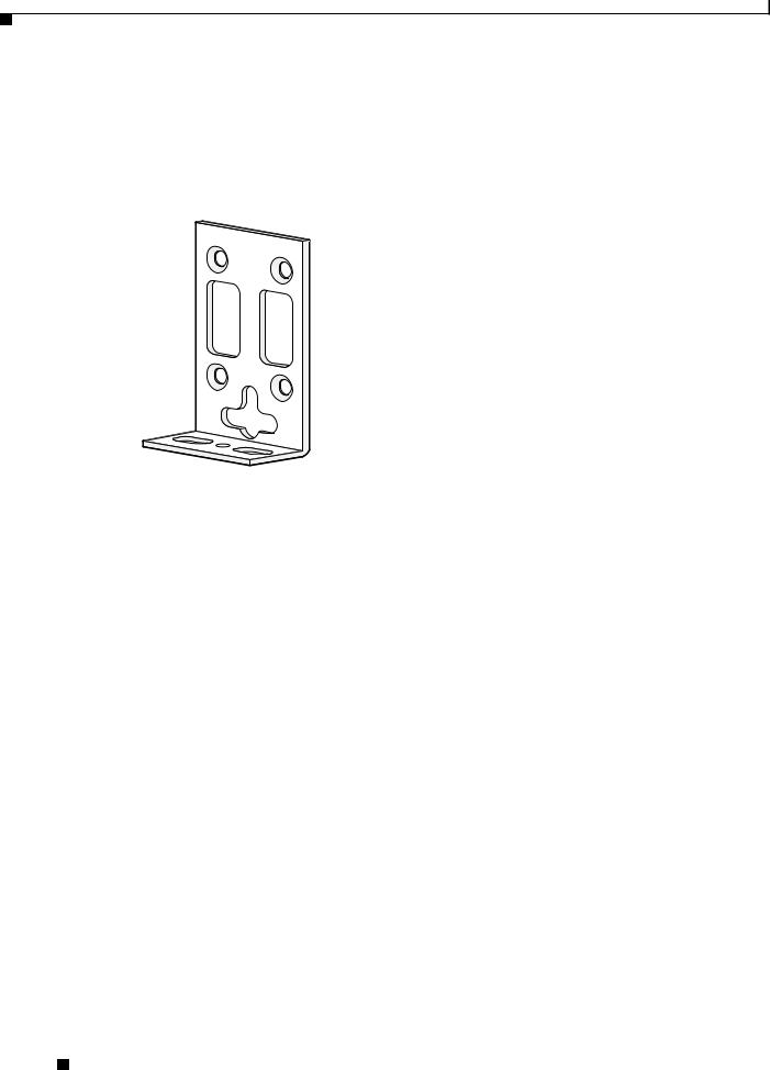
Your chassis ships with a pair of brackets for use with a 19-inch rack or mounting on the wall. The bracket is shown in Figure 3-2.
Figure 3-2 Quick Mounting Bracket
88815
Mounting Screws
Two sets of mounting screws are provided, in separate packages. Take care to use each screw type, and washers as needed, in the appropriate locations. Table 3-1 clarifies the differences between rack-mounting and wall-mounting screws.
Table 3-1 Rack-Mounting Versus Wall-Mounting Screws
Rack-mounting |
Wall-mounting |
||
|
|
|
|
• |
Eight countersunk Phillips head screws (four |
• |
Four 6–32 slotted hex screws (two per |
|
per bracket) |
|
bracket) and four plastic washers |
|
|
|
|
• |
Washers are not required |
• |
Washers are required |
|
|
|
|
Cisco VG224 Voice Gateway Hardware Installation Guide
3-6 |
OL-5006-04 |
|
|

Chapter 3 Installing the Cisco VG224 Voice Gateway
Rack-Mounting the Chassis
Attaching the Brackets
To install the chassis in a rack with the front panel forward, attach the brackets as shown in Figure 3-3.
Figure 3-3 19-Inch Rack Installation—Front Panel Forward
95915


 CISCO VG224
To install the chassis in a rack with the rear panel forward, attach the brackets as shown in Figure 3-4.
Figure 3-4 19-Inch Rack Installation—Rear Panel Forward
95916
VG224-24FXS
To install the chassis in a center-mount telco rack, attach the brackets as shown in Figure 3-5.
Figure 3-5 Telco 19-Inch Rack Installation—Rear Panel Forward
95917
VG224-24FXS 


Cisco VG224 Voice Gateway Hardware Installation Guide
|
OL-5006-04 |
3-7 |
|
|
|

Chapter 3 Installing the Cisco VG224 Voice Gateway
Rack-Mounting the Chassis
Installing the Cisco VG224 Voice Gateway in a Rack
The following warning applies only when the unit is rack-mounted:
Warning To prevent bodily injury when mounting or servicing this unit in a rack, you must take special precautions to ensure that the system remains stable. The following guidelines are provided to ensure your safety:
This unit should be mounted at the bottom of the rack if it is the only unit in the rack.
When mounting this unit in a partially filled rack, load the rack from the bottom to the top with the heaviest component at the bottom of the rack.
If the rack is provided with stabilizing devices, install the stabilizers before mounting or servicing the unit in the rack.
Statement 1006
To rack-mount the chassis, follow this procedure:
Step 1 Choose one of the methods shown in Figure 3-3 on page 3-7, Figure 3-4 on page 3-7, or Figure 3-5 on page 3-7, and attach the long leg of the mounting brackets to the chassis, as shown.
Caution Make sure to use the correct screws for this mounting option (see Table 3-1 on page 3-6).
Screws are included for attaching the brackets to the chassis, but not for installing the chassis in a rack or on a wall. You need four additional machine screws to install the chassis in a rack. Use the screw size required by your rack. After the brackets are secured to the chassis, you can rack-mount the chassis.
Step 2 Using screws that you provide, attach the chassis to the rack as shown in Figure 3-6 on page 3-8.
Figure 3-6 Attaching the Chassis to the 19-Inch Rack
VG224


103039
Cisco VG224 Voice Gateway Hardware Installation Guide
3-8 |
OL-5006-04 |
|
|
Loading...