


 Loading...
Catalyst 3650 Switch Getting Started Guide
•About This Guide, page 1
•Shipping Box Contents, page 2
•Running Express Setup, page 3
•Managing the Switch, page 7
•Installing the Switch, page 10
•Securing the AC Power Cord (Optional), page 14
•Connecting the StackWise Cables, page 14
•StackWise Cabling Configurations, page 17
•Connecting to the Switch Ports, page 17
•Troubleshooting, page 19
•Obtaining Documentation and Submitting a Service Request, page 20
•Related Documentation, page 21
About This Guide
This guide describes how to use Express Setup to initially configure your Catalyst 3650 switch. The guide also covers switch management options, installation, basic rack-mounting, stacking, port and module connections, and troubleshooting.
Note The illustrations of the Catalyst 3650 switch are not intended to depict any particular color scheme. They are provided as a reference for various features and markings described within this guide.
For more installation and configuration information, see the Catalyst 3650 documentation on Cisco.com. For system requirements, important notes, limitations, open and resolved bugs, and documentation updates, see the Catalyst 3650 release notes on Cisco.com.
When using the online publications, refer to the documents that match the Cisco IOS software version running on the switch.
Cisco Systems, Inc.
www.cisco.com
Shipping Box Contents
For translations of the warnings that appear in this publication, see the Regulatory Compliance and Safety Information for the Catalyst 3650 Switch on Cisco.com.
Shipping Box Contents
The shipping box contains the model of the switch you ordered and other components needed for installation, as shown in Figure 1. Some components are optional, depending on your order.
Note Verify that you have received these items. If any item is missing or damaged, contact your Cisco representative or reseller for instructions.
Figure 1 |
Components Delivered in the Shipping Box |
01X
12X |
13X |
24X |
25X |
36X |
37X |
48X
1
4 5
|
Catalyst 3650 48PoE+ 2X10G |
|
||
G1 |
G2 |
G3 |
TE3 G4 |
TE4 |
|
|
|||
|
|
and |
|
2 |
3 |
|
|
|
|
7 |
10 |
|
8 |
|
|
|
|
6 |
9 |
11 |
|
|
12 |
13 |
14 |
15 |
390176
1 |
|
Catalyst 36501 switch2 (power supplies |
9 |
Eight number-8 Phillips flat-head screws |
|||
|
|
and fan modules not shown)3 |
|
|
|
||
2 |
|
(Optional) AC power cord2 |
10 |
Cable guide |
|||
3 |
|
Product documentation and compliance |
11 |
M4.0 x 20mm Phillips pan-head screw |
|||
|
|
document |
|
|
|
||
|
|
|
|
|
|||
4 |
|
Four rubber mounting feet |
12 |
(Optional) RJ-45 console cable2 |
|||
5 |
|
Ground lug screw and ring terminal |
13 |
(Optional) USB console cable2 |
|||
6 |
|
Two 19-inch mounting brackets |
14 |
(Optional) StackWise (Stackwise-160) cable to connect a Catalyst 3650 |
|||
|
|
|
|
|
|
switch to another Catalyst 3650 switch (0.5-meter, 1-meter, or 3-meter)2 |
|
7 |
|
Four number-12 pan-head screws |
15 |
(Optional) Two StackWise (Stackwise-160) adapters2 |
|||
8 |
|
Four number-10 pan-head screws |
|
|
|
||
|
|
|
|
|
|
|
|
|
|
|
|
Catalyst 3650 Switch Getting Started Guide |
|
|
|
|
|
|
|
|
|
|
|
|
|
|
|
|
|
|
|
|
2 |
|
|
|
OL-29733-01 |
|
|
|
|
|
|
|
|||
Running Express Setup
1.Catalyst 3650-48PS-L switch is shown. Your switch model might look different.
2.Item is orderable.
3.Fan modules are installed in the switch. Power supply modules are not installed in the switch.
Running Express Setup
Use Express Setup to enter the initial IP information. This action enables the switch to connect to local routers and the Internet. You can access the switch through the IP address for further configuration.
Note To use the CLI-based initial setup program, see Appendix C, “Configuring the Switch with the CLI-Based Setup Program,” in the Catalyst 3650 Switch Hardware Installation Guide.
You need this equipment:
•PC or laptop with Windows Vista, XP, or 7
•Browser (Internet Explorer 5.5, 6.0, or 7.0, or Firefox 1.5, 2.0, or 3.0) with JavaScript enabled
•Straight-through or crossover Category 5 Ethernet cable
Note Before running Express Setup, disable any pop-up blockers or proxy settings in your browser and any wireless client running on your PC or laptop.
To run Express Setup:
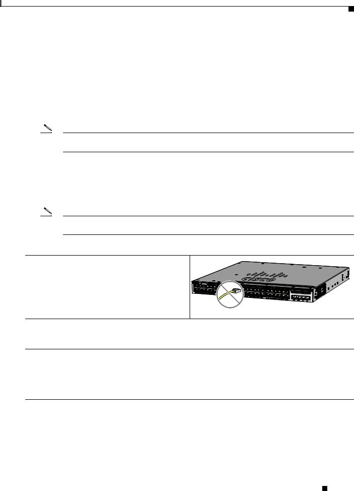
Step 1 Make sure that nothing is connected to the switch.
347774
Catalyst 3650 48 PoE+ 2X10G
G3 
TE3
G4 
TE4
Step 2 During Express Setup, the switch acts as a DHCP server. If your PC or laptop has a static IP address, temporarily change your PC or laptop settings before you use DHCP.
Note Write down the static IP address. You will need this IP address in Step 14.
Step 3 Install the power supply modules. See the “Power Supply Installation” chapter in the Catalyst 3650 Switch Hardware Installation Guide for instructions.
http://www.cisco.com/go/cat3650_hw
Note For information on 250-W AC power supply support on the PoE-capable switch models, refer to the Release Notes for the Cisco Catalyst 3650 Switch on Cisco.com.
Catalyst 3650 Switch Getting Started Guide
|
OL-29733-01 |
3 |
|
|
|

Running Express Setup
Step 4 Power the switch.
AC power switches: Plug the AC power cord into the switch power supply and into a grounded AC outlet.
DC power switches: See the wiring instructions in the
Catalyst 3650 Switch Hardware Installation Guide on Cisco.com:
http://www.cisco.com/go/cat3650_hw
CONSOLE |
MGMT |
PWR-C2-250WAC PWR-C2-640WAC
347767
Step 5 Observe the POST results. Approximately 30 seconds after the switch powers on, it begins the power-on self-test (POST), which can take up to 5 minutes to complete.
During POST, the SYSTEM LED blinks green. When POST is complete, the SYSTEM LED turns solid green. The ACTV LED is green if the switch is acting as the active switch.
Note Before going to the next step, wait until POST is complete.
Troubleshooting:
If the SYST LED does not turn solid green, or turns amber, the switch failed the POST. Contact your Cisco representative or reseller.
Step 6 Press and hold the Mode button until all the LEDs next to the Mode button turn green.
You might need to hold the button for more than 3 seconds.
The switch is now in Express Setup mode.
Catalyst 3650 48 PoE+ 2X10G |
|
ACTV |
|
TE3 |
TE4 |
Troubleshooting:
If the LEDs next to the Mode button blink when you press the button, release it. Blinking LEDs mean that the switch is already configured and cannot go into Express Setup mode. For more information, see the “Resetting the Switch” section on page 20.
347817
Catalyst 3650 Switch Getting Started Guide
4 |
OL-29733-01 |
|
|
Running Express Setup
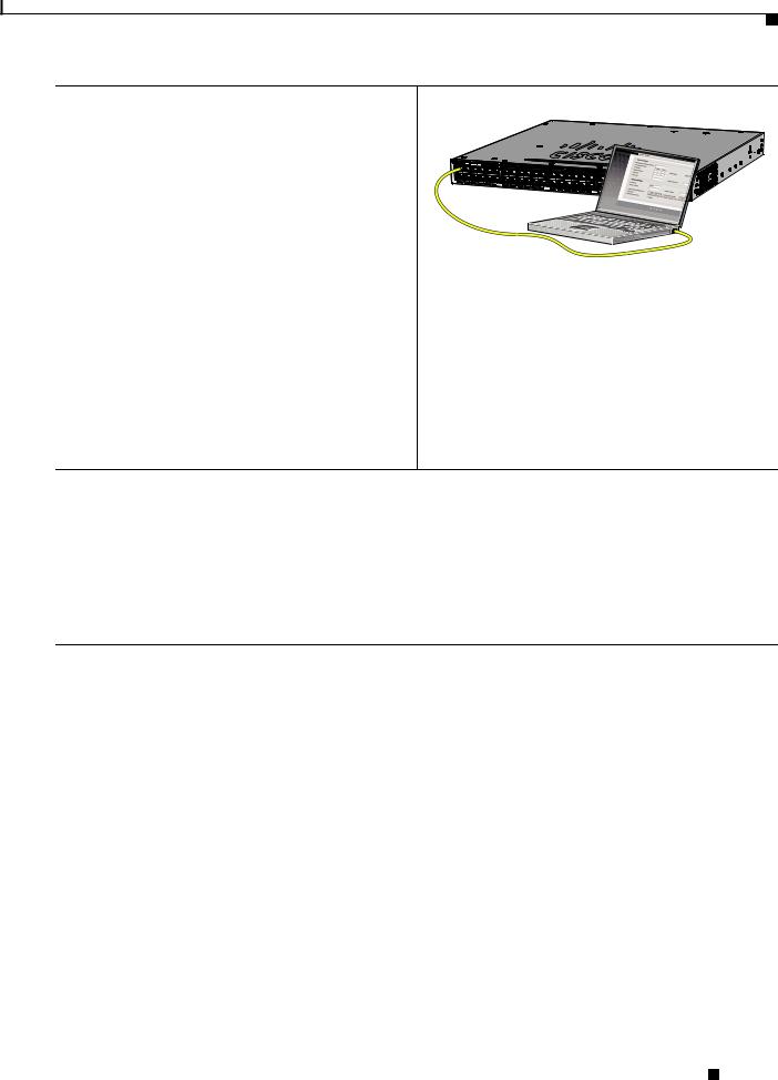
Step 7 Connect a Category 5 Ethernet cable to a port:
•Any 10/100/1000 or 10/100/1000 PoE+ Ethernet ports on the switch front panel.
• The RJ-45 management port on the switch rear panel.
Connect the other end of the cable to the Ethernet port on your PC or laptop.
Wait until the port LEDs on the switch and your PC or laptop are green or blinking green. Green LEDs indicate a successful connection.
Troubleshooting:
If the port LEDs do not turn green after about 30 seconds, make sure that:
•You connected the Ethernet cable to one of the downlink switch ports (not to the console port).
•You are using an undamaged Category 5 or 6 Ethernet cable.
•The other device is turned on.
Step 8 Start a browser session on the PC or laptop, and enter the IP address https://10.0.0.1. When prompted, enter the default password, cisco.
347820
Note The switch ignores text in the username field.
The Express Setup window appears.
Troubleshooting:
If the Express Setup window does not appear, make sure that any browser pop-up blockers or proxy settings are disabled and that any wireless client is disabled on your PC or laptop.
Catalyst 3650 Switch Getting Started Guide
|
OL-29733-01 |
5 |
|
|
|

Running Express Setup
Step 9 Enter this information in the Network Settings fields:
Note All entries must be in English letters.
• In the Management Interface (VLAN ID) field, the default is 1.
Note We recommend that you use the default VLAN value. During Express Setup, VLAN 1 is the only VLAN on the switch. Enter a new VLAN ID only if you want to change the management interface through which you manage the switch. The VLAN ID range is 1 to 1001.
•In the IP Address field, enter the switch IP address.
•In the Subnet Mask field, click the drop-down arrow, and select a subnet mask.
•In the Default Gateway field, enter the IP address for the default gateway (router).
•Enter your password in the Switch Password field. The password can be from 2 to 25 alphanumeric characters, can start with a number, is case sensitive, allows embedded spaces, but does not allow spaces at the beginning or end. In the Confirm Switch Password field, enter your password again.
Note You must change the default password, cisco.
(Optional) Enter this information in the Ethernet Management Port Settings fields:
•In the IP Address field, enter the IP address of the Ethernet management port. In the Subnet Mask field, click the drop-down arrow, and select an IP Subnet Mask.
Step 10 (Optional) You can enter other administrative settings in the Optional Settings fields. You can enter the Optional Settings information now or enter it later using the Device Manager interface. For example, the optional administrative settings identify and synchronize the switch for enhanced management. NTP automatically synchronizes the switch clock with the network clock. You can manually set the system clock if the switch should have different settings.
Step 11 (Optional) You can select the Advanced Settings tab on the Express Setup window and enter the advanced settings now or enter them later using the Device Manager interface.
•In the Telnet Access field, click Enable if you are going to use Telnet to manage the switch by using the command-line interface (CLI). If you enable Telnet access, you must enter a Telnet password.
•In the Telnet Password field, enter a password. The Telnet password can be from 1 to 25 alphanumeric characters, is case sensitive, allows embedded spaces, but does not allow spaces at the beginning or end. In the Confirm Telnet Password field, reenter the Telnet password.
•In the SNMP field, click Enable to enable Simple Network Management Protocol (SNMP). Enable SNMP only if you plan to manage switches by using Cisco Network Assistant or another SNMP-based network-management system.
•If you enable SNMP, you must enter a community string in the SNMP Read Community field, the SNMP Write Community field, or both. SNMP community strings authenticate access to MIB objects. Embedded spaces are not allowed in SNMP community strings. When you set the SNMP read community, you can access SNMP information, but you cannot change it. When you set the SNMP write community, you can both access and change SNMP information.
•In the System Contact and System Location fields, enter a contact name and the wiring closet, floor, or building where the switch is located.
•(Optional) In the Enable IPv6 field, click Enable to enable IPv6 on the switch. The IPv6 field is enabled by default.
Note Enabling IPv6 restarts the switch when you complete Express Setup.
Catalyst 3650 Switch Getting Started Guide
6 |
OL-29733-01 |
|
|

Managing the Switch
Step 12 Click Submit to save your changes and to complete the initial setup.
After you click Submit:
•The switch is configured and exits Express Setup mode.
•The browser displays a warning message and tries to connect with the earlier switch IP address. Typically, connectivity between the PC or laptop and the switch is lost because the configured switch IP address is in a different subnet from the IP address on the PC or laptop.
For more information about Express Setup fields, see the online help for the Express Setup window.
Step 13 Disconnect the switch from the PC and laptop, and install the switch in your network. See the “Installing the Switch” section on page 10.
Step 14 If you changed the static IP address on your PC or laptop in Step 2, change it to the previously configured static IP address.
Step 15 See the “Managing the Switch” section on page 7 for information about configuring and managing the switch.
Managing the Switch
After completing Express Setup and installing the switch in your network, you can use these options for configuration:
•Configuration Wizard
•Device Manager
•Cisco Network Assistant
•Command-Line Interface
•Other Management Options
Configuration Wizard
The Configuration Wizard is a Web-based controller user interface (UI) that lets you complete the initial wireless configuration after you configure the IP address, local username, and password or authorization using the authentication server. Using the Web UI, you can configure the controller, WLAN, and radios for all initial operations, establish management parameters, set security policies, access software management commands, configure system logs, and other tasks.
For more information on using the Configuration Wizard, see switch software configuration guide on Cisco.com
Device Manager
The simplest way to manage the switch is by using Device Manager in the switch memory. Use Device Manager for basic switch configuration and monitoring. This web interface offers quick configuration and monitoring. You can access it through a web browser.
To display Device Manager:
Step 1 Start a web browser on your PC or laptop.
Catalyst 3650 Switch Getting Started Guide
|
OL-29733-01 |
7 |
|
|
|
Loading...