


 Loading...
Catalyst 3560-C and 2960-C Switch
Hardware Installation Guide
March 2013
Americas Headquarters
Cisco Systems, Inc. 170 West Tasman Drive
San Jose, CA 95134-1706 USA http://www.cisco.com Tel: 408 526-4000
800 553-NETS (6387) Fax: 408 527-0883
Text Part Number: OL-23803-02
THE SPECIFICATIONS AND INFORMATION REGARDING THE PRODUCTS IN THIS MANUAL ARE SUBJECT TO CHANGE WITHOUT NOTICE. ALL STATEMENTS, INFORMATION, AND RECOMMENDATIONS IN THIS MANUAL ARE BELIEVED TO BE ACCURATE BUT ARE PRESENTED WITHOUT WARRANTY OF ANY KIND, EXPRESS OR IMPLIED. USERS MUST TAKE FULL RESPONSIBILITY FOR THEIR APPLICATION OF ANY PRODUCTS.
THE SOFTWARE LICENSE AND LIMITED WARRANTY FOR THE ACCOMPANYING PRODUCT ARE SET FORTH IN THE INFORMATION PACKET THAT SHIPPED WITH THE PRODUCT AND ARE INCORPORATED HEREIN BY THIS REFERENCE. IF YOU ARE UNABLE TO LOCATE THE SOFTWARE LICENSE OR LIMITED WARRANTY, CONTACT YOUR CISCO REPRESENTATIVE FOR A COPY.
The following information is for FCC compliance of Class A devices: This equipment has been tested and found to comply with the limits for a Class A digital device, pursuant to part 15 of the FCC rules. These limits are designed to provide reasonable protection against harmful interference when the equipment is operated in a commercial environment. This equipment generates, uses, and can radiate radio-frequency energy and, if not installed and used in accordance with the instruction manual, may cause harmful interference to radio communications. Operation of this equipment in a residential area is likely to cause harmful interference, in which case users will be required to correct the interference at their own expense.
The following information is for FCC compliance of Class B devices: This equipment has been tested and found to comply with the limits for a Class B digital device, pursuant to part 15 of the FCC rules. These limits are designed to provide reasonable protection against harmful interference in a residential installation. This equipment generates, uses and can radiate radio frequency energy and, if not installed and used in accordance with the instructions, may cause harmful interference to radio communications.
However, there is no guarantee that interference will not occur in a particular installation. If the equipment causes interference to radio or television reception, which can be determined by turning the equipment off and on, users are encouraged to try to correct the interference by using one or more of the following measures:
•Reorient or relocate the receiving antenna.
•Increase the separation between the equipment and receiver.
•Connect the equipment into an outlet on a circuit different from that to which the receiver is connected.
•Consult the dealer or an experienced radio/TV technician for help.
Modifications to this product not authorized by Cisco could void the FCC approval and negate your authority to operate the product.
The Cisco implementation of TCP header compression is an adaptation of a program developed by the University of California, Berkeley (UCB) as part of UCB’s public domain version of the UNIX operating system. All rights reserved. Copyright © 1981, Regents of the University of California.
NOTWITHSTANDING ANY OTHER WARRANTY HEREIN, ALL DOCUMENT FILES AND SOFTWARE OF THESE SUPPLIERS ARE PROVIDED “AS IS” WITH ALL FAULTS. CISCO AND THE ABOVE-NAMED SUPPLIERS DISCLAIM ALL WARRANTIES, EXPRESSED OR IMPLIED, INCLUDING, WITHOUT LIMITATION, THOSE OF MERCHANTABILITY, FITNESS FOR A PARTICULAR PURPOSE AND NONINFRINGEMENT OR ARISING FROM A COURSE OF DEALING, USAGE, OR TRADE PRACTICE.
Cisco and the Cisco logo are trademarks or registered trademarks of Cisco and/or its affiliates in the U.S. and other countries. To view a list of Cisco trademarks, go to this URL: www.cisco.com/go/trademarks. Third-party trademarks mentioned are the property of their respective owners. The use of the word partner does not imply a partnership relationship between Cisco and any other company. (1110R)
Any Internet Protocol (IP) addresses used in this document are not intended to be actual addresses. Any examples, command display output, and figures included in the document are shown for illustrative purposes only. Any use of actual IP addresses in illustrative content is unintentional and coincidental.
Catalyst 3560-C and 2960-C Switch Hardware Installation Guide
© 2011–2013 Cisco Systems, Inc. All rights reserved.

|
|
C O N T E N T S |
|
Preface vii |
|
|
Related Publications i-viii |
|
|
Obtaining Documentation and Submitting a Service Request i-viii |
|
|
Product Overview |
|
C H A P T E R 1 |
1-1 |
|
|
Switch Models |
1-1 |
|
Front Panel 1-2 |
|
10/100 and 10/100/1000 |
Fast Ethernet Downlink Ports 1-5 |
PoE Ports (Switches with |
PoE Ports) 1-5 |
PoE Pass-Through 1-6
PoE Uplink Ports (Catalyst 2960CPD-8TT-L, 2960CPD-8PT-L, and 3560CPD-8PT-S) 1-8
PoE-Capable Downlink Ports (Catalyst 2960CPD-8PT-L, 3560CG-8PC-S, 3560CPD-8PT-S, 2960C-8PC-L, 2960C-12PC-L, 3560C-8PC-S, and 3560C-12PC-S) 1-9
USB Type A Port |
1-9 |
|
||
Dual-Purpose Ports |
1-9 |
|
||
SFP Modules |
1-9 |
|
||
Management Ports |
1-11 |
|||
LEDs |
1-12 |
|
|
|
Switch Panel LEDs |
1-12 |
|||
System LED |
1-13 |
|
||
Console LEDs |
1-13 |
|
||
Modes for Port LEDs |
1-14 |
|||
Port LEDs |
1-14 |
|
||
PoE LED |
1-15 |
|
||
PD LED |
1-15 |
|
|
|
Dual-Purpose Port LEDs 1-15 |
||||
Rear Panel |
1-16 |
|
|
|
Internal Power Supply |
1-17 |
|||
Auxiliary Power Adapter |
1-17 |
|||
Security Slots |
1-18 |
|
||
Reset Button |
1-18 |
|
||
Management Options |
1-18 |
|
||
Network Configurations |
1-19 |
|||
Catalyst 3560-C and 2960-C Switch Hardware Installation Guide
|
OL-23803-02 |
iii |
|

Contents
C H A P T E R |
2 |
|
Switch Installation |
2-1 |
|
|
|
|
|
|
|
|
|
|||
|
|
|
|
|
Preparing for Installation |
2-1 |
|
|
|
|
|
|
|
|||
|
|
|
|
|
Warnings |
2-1 |
|
|
|
|
|
|
|
|
|
|
|
|
|
|
|
Installation Guidelines |
2-3 |
|
|
|
|
|
|
|
|||
|
|
|
|
|
Equipment That You Supply |
2-4 |
|
|
|
|
|
|
||||
|
|
|
|
|
Box Contents |
2-4 |
|
|
|
|
|
|
|
|
|
|
|
|
|
|
|
Powering the Switch |
2-4 |
|
|
|
|
|
|
|
|
||
|
|
|
|
|
Verifying Switch Operation |
2-5 |
|
|
|
|
|
|
|
|||
|
|
|
|
|
Mounting the Switch |
2-5 |
|
|
|
|
|
|
|
|
||
|
|
|
|
|
On a Desk or Shelf (without Mounting Screws) |
|
2-6 |
|
||||||||
|
|
|
|
|
Desk, Shelf, or Wall (with Mounting Screws) |
2-6 |
|
|||||||||
|
|
|
|
|
Deskor Shelf-Mounting |
2-6 |
|
|
|
|
|
|||||
|
|
|
|
|
Under the Deskor Shelf-Mounting |
2-8 |
|
|
|
|||||||
|
|
|
|
|
Wall-Mounting |
2-10 |
|
|
|
|
|
|
|
|||
|
|
|
|
|
With a Mounting Tray |
2-13 |
|
|
|
|
|
|
|
|||
|
|
|
|
|
Mounting Tray with Screws |
2-13 |
|
|
|
|
||||||
|
|
|
|
|
Mounting Tray with a Magnet |
|
2-15 |
|
|
|
|
|||||
|
|
|
|
|
In a Rack |
2-18 |
|
|
|
|
|
|
|
|
|
|
|
|
|
|
|
Attaching Brackets to the Switch |
2-18 |
|
|
|
|||||||
|
|
|
|
|
Mounting the Switch in a Rack |
2-19 |
|
|
|
|
||||||
|
|
|
|
|
On a DIN Rail |
2-20 |
|
|
|
|
|
|
|
|
||
|
|
|
|
|
Attaching the DIN-Mount Tray to the Switch |
2-20 |
|
|||||||||
|
|
|
|
|
Mounting the Switch on a DIN Rail |
2-21 |
|
|
|
|||||||
|
|
|
|
|
Removing the Switch from a DIN Rail |
2-23 |
|
|
||||||||
|
|
|
|
|
Installing a Cover for the Reset Button (Optional) |
2-24 |
|
|||||||||
|
|
|
|
|
Installing the Power Cord Retainer (Optional) |
2-25 |
|
|
|
|||||||
|
|
|
|
|
Installing the Cable Guard (Optional) |
2-28 |
|
|
|
|
||||||
|
|
|
|
|
After Installing the Switch |
2-31 |
|
|
|
|
|
|
|
|||
|
|
|
|
|
Installing SFP Modules |
2-31 |
|
|
|
|
|
|
|
|||
|
|
|
|
|
Removing SFP Modules |
2-32 |
|
|
|
|
|
|
|
|||
|
|
|
|
|
Connecting Devices to the Ethernet Ports |
2-33 |
|
|
|
|||||||
|
|
|
|
|
Connecting to the 10/100 and 10/100/1000 Ports |
2-33 |
|
|||||||||
|
|
|
|
|
Connecting to the PoE Ports |
2-34 |
|
|
|
|
|
|
||||
|
|
|
|
|
Where to Go Next |
2-35 |
|
|
|
|
|
|
|
|
||
|
|
|
Troubleshooting |
|
|
|
|
|
|
|
|
|
|
|
||
C H A P T E R |
3 |
|
3-1 |
|
|
|
|
|
|
|
|
|
|
|||
|
|
|
|
|
Diagnosing Problems |
3-1 |
|
|
|
|
|
|
|
|
||
|
|
|
|
|
Switch POST Results |
3-1 |
|
|
|
|
|
|
|
|||
|
|
|
|
Catalyst 3560-C and 2960-C Switch Hardware Installation Guide |
|
|
|
|
|
|
||||||
|
|
|
|
|
|
|
|
|
|
|||||||
|
|
|
|
|
|
|
|
|
|
|
|
|
|
|
|
|
|
iv |
|
|
|
|
|
|
|
|
|
|
|
|
|
OL-23803-02 |
|
|
|
|
|
|
|
|
|
|
|
|
|
|
|
|
||

Contents
|
|
|
Switch LEDs 3-2 |
|
|
|
|
|
|
|
|
|
|
|
|
|
Switch Connections |
3-2 |
|
|
|
|
|
|
|
||
|
|
|
Bad or Damaged Cable 3-2 |
|
|
|
|
|
|
||||
|
|
|
Ethernet and Fiber-Optic Cables 3-2 |
|
|
|
|
|
|
||||
|
|
|
Link Status |
3-2 |
|
|
|
|
|
|
|
|
|
|
|
|
10/100 and 10/100/1000 Port Connections |
3-3 |
|
|
|
|
|||||
|
|
|
10/100 PoE or PoE+ Port Connections |
3-3 |
|
|
|
|
|
||||
|
|
|
SFP Module |
3-3 |
|
|
|
|
|
|
|
|
|
|
|
|
Interface Settings |
3-3 |
|
|
|
|
|
|
|
||
|
|
|
Ping End Device |
3-3 |
|
|
|
|
|
|
|
||
|
|
|
Spanning Tree Loops |
3-4 |
|
|
|
|
|
|
|
||
|
|
|
Switch Performance |
3-4 |
|
|
|
|
|
|
|
||
|
|
|
Speed, Duplex, and Autonegotiation |
3-4 |
|
|
|
|
|
||||
|
|
|
Autonegotiation and Network Interface Cards |
3-4 |
|
|
|
|
|||||
|
|
|
Cabling Distance |
3-4 |
|
|
|
|
|
|
|
||
|
|
|
Resetting the Switch |
3-5 |
|
|
|
|
|
|
|
|
|
|
|
|
Finding the Switch Serial Number |
3-5 |
|
|
|
|
|
|
|||
|
|
Technical Specifications |
|
|
|
|
|
|
|
|
|
||
A P P E N D I X |
A |
A-1 |
|
|
|
|
|
|
|
|
|||
|
|
Connector and Cable Specifications |
|
|
|
|
|
|
|
||||
A P P E N D I X |
B |
B-1 |
|
|
|
|
|
|
|||||
|
|
|
Connector Specifications |
B-1 |
|
|
|
|
|
|
|
||
|
|
|
10/100 and 10/100/1000 Ports |
B-1 |
|
|
|
|
|
|
|||
|
|
|
SFP Module Connectors |
B-2 |
|
|
|
|
|
|
|
||
|
|
|
Dual-Purpose Ports |
B-2 |
|
|
|
|
|
|
|
|
|
|
|
|
Cables and Adapters |
B-3 |
|
|
|
|
|
|
|
|
|
|
|
|
SFP Module Cables |
B-3 |
|
|
|
|
|
|
|
||
|
|
|
Cable Pinouts |
B-4 |
|
|
|
|
|
|
|
|
|
|
|
|
Console Port Adapter Pinouts |
B-5 |
|
|
|
|
|
|
|||
|
|
Configuring the Switch with the CLI Setup Program |
|
|
|
|
|
||||||
A P P E N D I X |
C |
C-1 |
|
|
|
|
|||||||
|
|
|
Accessing the CLI Through the Console Port |
C-1 |
|
|
|
|
|
||||
|
|
|
RJ-45 Console Port |
C-1 |
|
|
|
|
|
|
|
|
|
|
|
|
USB Mini-Type B Console Port |
C-3 |
|
|
|
|
|
|
|||
|
|
|
Installing the Cisco Microsoft Windows USB Device Drivers |
C-4 |
|||||||||
|
|
|
Installing the Cisco Microsoft Windows XP USB Driver |
C-4 |
|||||||||
|
|
|
Installing the Cisco Microsoft Windows 2000 USB Driver |
C-5 |
|||||||||
|
|
|
Installing the Cisco Microsoft Windows Vista and Windows 7 USB Driver C-5 |
||||||||||
|
|
|
Uninstalling the Cisco Microsoft Windows USB Drivers C-6 |
|
|
|
|
||||||
|
|
|
|
|
|
|
Catalyst 3560-C and 2960-C Switch Hardware Installation Guide |
|
|
|
|||
|
|
|
|
|
|
|
|
||||||
|
|
|
|
|
|
|
|
|
|
|
|
|
|
|
OL-23803-02 |
|
|
|
|
|
|
|
|
|
|
v |
|
|
|
|
|
|
|
|
|
|
|
|
|
||

Contents
Uninstalling the Cisco Microsoft Windows XP and 2000 USB Driver C-6
Uninstalling the Cisco Microsoft Windows Vista and Windows 7 USB Driver C-6
Entering the Initial Configuration Information C-7
IP Settings C-7
Completing the Setup Program C-7
Catalyst 3560-C and 2960-C Switch Hardware Installation Guide
|
vi |
OL-23803-02 |
|
|
|

Preface
This guide describes the hardware features of the Catalyst 3560-C and 2960-C switches. It describes the physical and performance characteristics of the switch, explains how to install it, and provides troubleshooting information.
This guide does not describe system messages that you might receive or how to configure your switch. See the switch software configuration guide, the switch command reference, and the switch system message guide on Cisco.com.
Note Means reader take note. Notes contain helpful suggestions or references to materials not contained in this manual.
Caution Means reader be careful. In this situation, you might do something that could result in equipment damage or loss of data.
Warning IMPORTANT SAFETY INSTRUCTIONS
This warning symbol means danger. You are in a situation that could cause bodily injury. Before you work on any equipment, be aware of the hazards involved with electrical circuitry and be familiar with standard practices for preventing accidents. Use the statement number provided at the end of each warning to locate its translation in the translated safety warnings that accompanied this device. Statement 1071
SAVE THESE INSTRUCTIONS
The safety warnings for this product are translated into several languages in the Regulatory Compliance and Safety Information for the Catalyst 3560-C and 2960-C Switches that is available on Cisco.com. The EMC regulatory statements are also included in that guide.
Catalyst 3560-C and 2960-C Switch Hardware Installation Guide
|
OL-23803-02 |
vii |
|

Preface
Related Publications
Related Publications
http://www.cisco.com/go/cat3560c_docs
http://www.cisco.com/go/cat2960c_docs
Note Before installing, configuring, or upgrading the switch, see the release notes on Cisco.com for the latest information.
•Release Notes for the Catalyst 3560-C Switch
•Release Notes for the Catalyst 2960-C Switch
•Catalyst 3560-C and 2960-C Switch Getting Started Guide
•Regulatory Compliance and Safety Information for the Catalyst 3560-C and 2960-C Switches
•Catalyst 2960 and 2960-S Switch Software Configuration Guide
•Catalyst 2960 and 2960-S Switch Command Reference
•Catalyst 3560 Switch Software Configuration Guide
•Catalyst 3560 Switch Command Reference
•Catalyst 3750, 3560, 3550, 2975, 2970, 2960, and 2960-S Switch System Message Guide
For other information about related products, see these documents:
•Smart Install Configuration Guide
•Auto Smartports Configuration Guide
•Cisco EnergyWise Configuration Guide
Cisco SFP module documents:
http://www.cisco.com/en/US/products/hw/modules/ps5455/prod_installation_guides_list.html
SFP module compatibility matrix documents:
http://www.cisco.com/en/US/products/hw/modules/ps5455/products_device_support_tables_list.html
Obtaining Documentation and Submitting a Service Request
For information on obtaining documentation, submitting a service request, and gathering additional information, see the monthly What’s New in Cisco Product Documentation, which also lists all new and revised Cisco technical documentation, at:
http://www.cisco.com/en/US/docs/general/whatsnew/whatsnew.html
Subscribe to the What’s New in Cisco Product Documentation as a Really Simple Syndication (RSS) feed and set content to be delivered directly to your desktop using a reader application. The RSS feeds are a free service and Cisco currently supports RSS version 2.0.
Catalyst 3560-C and 2960-C Switch Hardware Installation Guide
|
viii |
OL-23803-02 |
|
|
|

C H A P T E R 1
Product Overview
The Catalyst 3560-C and 2960-C of switches, also referred to as the switch, are Ethernet switches to which you can connect devices such as Cisco IP Phones, Cisco Wireless Access Points, workstations, and other network devices such as servers, routers, and other switches.
You can deploy these switches outside of the traditional wiring closet environment, such as in office workspaces, hotel rooms, slot machines, kiosks, and classrooms. The switch is suitable for deployments where there are space and power constraints (access to power outlets).
See the switch software configuration guide for deployment examples.
•Switch Models, page 1-1
•Front Panel, page 1-2
•Rear Panel, page 1-16
•Management Options, page 1-18
Switch Models
Table 1-1 |
Switch Model Descriptions |
||
|
|
|
|
Switch Model |
|
Description |
|
|
|
|
|
Catalyst 2960CPD-8TT-L |
8 |
10/100 Ethernet ports and 2 10/100/1000BASE-T PD uplink copper ports. |
|
|
|
|
|
Catalyst 2960CPD-8PT-L |
8 |
10/100 PoE1 ports and 2 10/100/1000BASE-T PD uplink copper ports. |
|
Catalyst 2960CG-8TC-L |
8 10/100/1000 Ethernet ports and 2 dual-purpose ports (1 10/100/1000BASE-T copper port and |
||
|
|
1 |
SFP2 module slot). |
Catalyst 2960C-8TC-L |
8 |
10/100 Ethernet ports and 2 dual-purpose ports. |
|
|
|
|
|
Catalyst 2960C-8TC-S |
8 |
10/100 Ethernet ports and 2 dual-purpose ports. |
|
|
|
|
|
Catalyst 2960C-8PC-L |
8 |
10/100 PoE ports and 2 dual-purpose ports. |
|
|
|
||
Catalyst 2960C-12PC-L |
12 10/100 PoE ports and 2 dual-purpose ports. |
||
|
|
|
|
Catalyst 3560CG-8PC-S |
8 |
10/100/1000 PoE+ ports and 2 dual-purpose ports. |
|
|
|
|
|
Catalyst 3560CG-8TC-S |
8 |
10/100/1000 Ethernet ports and 2 dual-purpose ports. |
|
|
|
|
|
Catalyst 3560CPD-8PT-S |
8 |
10/100/1000 PoE ports and 2 10/100/1000BASE-T PD uplink copper ports. |
|
|
|
|
|
Catalyst 3560-C and 2960-C Switch Hardware Installation Guide
|
OL-23803-02 |
1-1 |
|
|
|

Chapter 1 Product Overview
Front Panel
Table 1-1 |
Switch Model Descriptions (continued) |
|
|
|
|
Switch Model |
|
Description |
|
|
|
Catalyst 3560C-8PC-S |
8 10/100 PoE+ ports and 2 dual-purpose ports. |
|
|
|
|
Catalyst 3560C-12PC-S |
12 10/100 PoE+ ports and 2 dual-purpose ports. |
|
|
|
|
1.PoE = Power over Ethernet
2.SFP = small form-factor pluggable
Front Panel
•8 or 12 downlink Ethernet ports of one of these types:
–10/100
–10/100/1000
–10/100 PoE
–10/100 PoE+
–10/100/1000 PoE
–10/100/1000 PoE+
•Two 10/100/1000 uplink ports or two dual purpose ports
•RJ-45 console port
•USB mini-Type B (console) port
•USB Type A port (available on the Catalyst 3560CPD-8PT-S, 2960CG-8TC-L, 3560CG-8PC-S, and 3560CG-8TC-S switches)
•LEDs
All the 8-port and 12-port switches have similar components. See Figure 1-1, Figure 1-2, Figure 1-3, Figure 1-4, and Figure 1-5 for examples.
Catalyst 3560-C and 2960-C Switch Hardware Installation Guide
1-2 |
OL-23803-02 |
|
|

Chapter 1 Product Overview
Front Panel
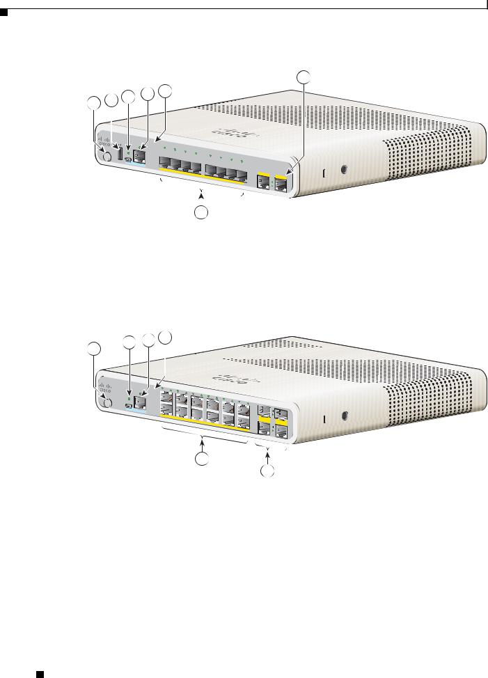
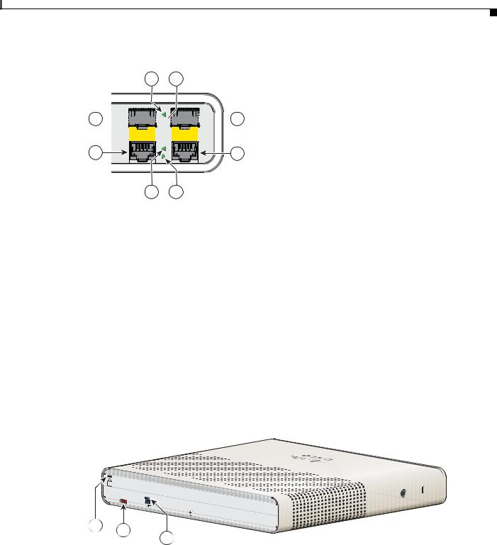
Figure 1-1 Catalyst 2960CPD-8PT-L Front Panel View
6
2 3 4
1
|
|
SYST |
|
|
|
|
|
|
|
|
|
|
|
|
STAT |
|
|
|
|
|
|
|
|
|
|
|
|
DPLX |
1 |
|
|
|
|
|
|
|
|
|
M O DE |
|
SPD |
2 |
|
|
|
|
|
|
|
||
|
|
|
3 |
|
|
|
S |
eries |
|
|||
|
|
PoE |
4 |
|
|
|
|
P |
||||
|
CONSO |
PD |
5 |
6 |
|
|
|
|||||
|
|
|
|
|
||||||||
|
LE |
|
|
|
|
|
7 |
|
|
|
|
|
|
|
|
|
|
|
|
8 |
|
|
|
|
|
|
|
|
PO |
|
|
|
|
|
|
|
|
|
|
|
|
W ER |
O |
|
|
|
|
|
|
|
|
|
|
|
|
VER |
ETH |
|
|
|
|
|
|
|
|
|
|
|
|
|
|
|
|
|
|||
|
|
|
|
|
ERNET |
|
|
1 |
|
|
|
|
|
|
|
|
|
|
|
|
|
2 |
|
||
|
|
|
|
|
|
|
|
|
|
|
|
|
|
|
|
|
|
|
|
|
|
|
|
|
|
|
|
|
|
|
|
|
|
|
|
|
|
|
282391
5
1 |
Mode button |
4 |
LEDs |
|
|
|
|
2 |
USB mini-Type B (console) port |
5 |
10/100 PoE ports |
|
|
|
|
3 |
RJ-45 console port |
6 |
10/100/1000 uplink ports |
|
|
|
|
Figure 1-2 Catalyst 3560CG-8PC-S Front Panel View
7
1 2 3 4 5
|
|
SYST |
|
|
|
|
|
|
|
|
|
|
|
|
|
STAT |
|
|
|
|
|
|
|
|
|
|
|
|
|
DPLX |
1 |
|
|
|
|
|
|
|
|
|
|
M O DE |
|
SPD |
2 |
|
|
|
C |
atalyst |
3560-CG |
|
|
||
|
|
PoE |
3 |
4 |
5 |
|
|
Series |
PoE |
||||
|
|
|
|
|
|
|
|
|
|
|
|
|
|
|
|
CO |
|
|
|
|
|
6 |
|
|
|
|
|
|
|
NSOLE |
|
|
|
|
|
7 |
|
|
|
|
|
|
|
|
|
|
|
|
|
8 |
|
|
|
|
|
|
|
|
PO |
|
|
|
|
|
|
|
|
|
|
|
|
|
W ER |
O |
|
|
|
|
|
|
|
|
|
|
|
|
|
VER |
ETH |
|
|
|
|
9 |
|
|
|
|
|
|
|
|
|
|
|
|
|
||||
|
|
|
|
|
ERNET |
|
|
|
|
|
|
||
|
|
|
|
|
|
|
|
|
|
|
10 |
|
|
|
|
|
|
|
|
|
|
|
|
|
|
|
|
|
|
|
|
|
|
|
|
|
|
|
|
|
|
208868
6
1 |
Mode button |
5 |
LEDs |
|
|
|
|
2 |
USB Type A port |
6 |
10/100/1000 PoE+ ports |
|
|
|
|
3 |
USB mini-Type B (console) port |
7 |
Dual-purpose ports |
|
|
|
|
4 |
RJ-45 console port |
|
|
|
|
|
|
Catalyst 3560-C and 2960-C Switch Hardware Installation Guide
|
OL-23803-02 |
1-3 |
|
|
|
Chapter 1 Product Overview
Front Panel
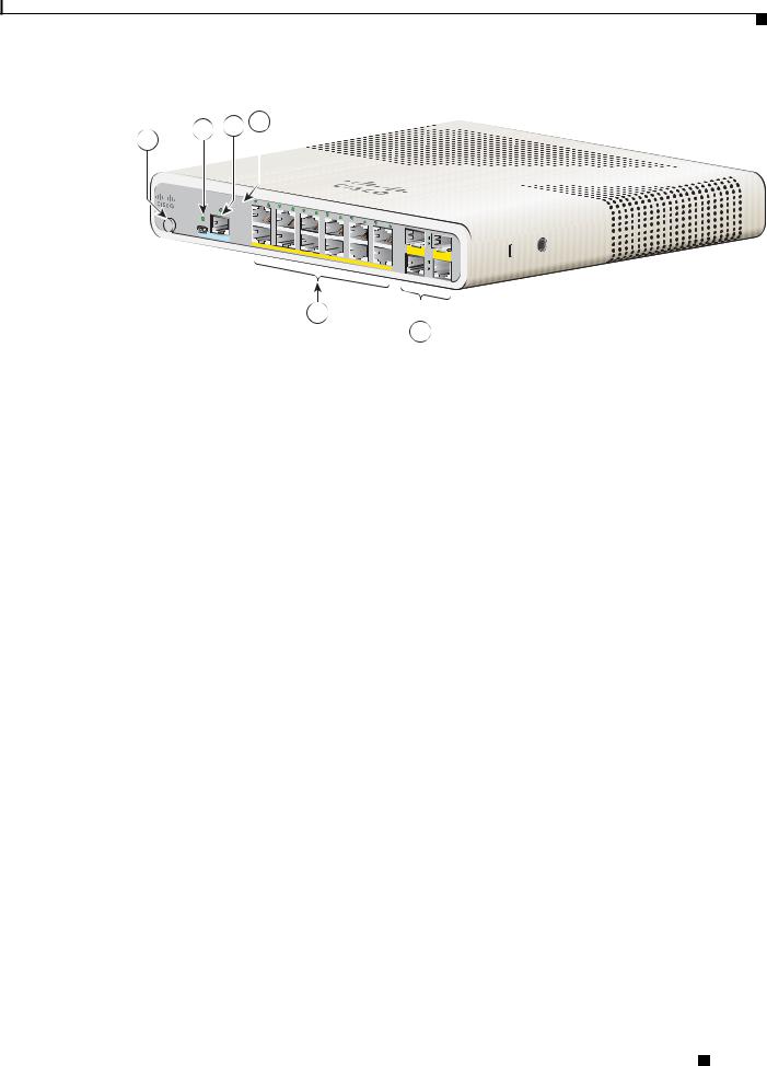
Figure 1-3 Catalyst 3560CPD-8PT-S Front Panel View
7
1 2 3 4 5
|
SYST |
|
|
|
|
|
|
|
|
|
|
|
|
STAT |
|
|
|
|
|
|
|
|
|
|
|
|
DPLX |
1 |
|
|
|
|
|
|
|
|
|
|
M O DE |
SPD |
2 |
|
|
|
C |
atalyst |
3560-CG |
|
|
||
|
PoE |
3 |
4 |
5 |
|
|
Series |
PD |
||||
|
PD |
|
|
|
|
|
|
|
|
|
|
|
|
|
|
|
|
|
6 |
|
|
|
|
|
|
|
CO |
|
|
|
|
|
7 |
|
|
|
|
|
|
NSOLE |
|
|
|
|
|
|
|
|
|
|
|
|
|
|
|
|
|
|
8 |
|
|
|
|
|
|
|
PO |
|
|
|
|
|
|
|
|
|
|
|
|
W ER |
O |
|
|
|
|
|
|
|
|
|
|
|
|
VER |
ETH |
|
|
|
|
|
|
|
|
|
|
|
|
|
|
|
|
|
|
|
||
|
|
|
|
ERNET |
|
|
|
|
1 |
|
|
|
|
|
|
|
|
|
|
|
|
|
|
||
|
|
|
|
|
|
|
|
|
|
2 |
|
|
|
|
|
|
|
|
|
|
|
|
|
|
|
|
|
|
|
|
|
|
|
|
|
|
|
|
208867
6
1 |
Mode button |
5 |
LEDs |
|
|
|
|
2 |
USB Type A port |
6 |
10/100/1000 PoE ports |
|
|
|
|
3 |
USB mini-Type B (console) port |
7 |
10/100/1000 uplink ports |
|
|
|
|
4 |
RJ-45 console port |
|
|
|
|
|
|
Figure 1-4 Catalyst 2960C-12PC-L Front Panel View
1
M ODE
2 3 4
|
SYST |
|
|
|
|
|
|
STAT |
|
|
|
|
|
|
DPLX |
1 |
|
|
|
|
|
3 |
|
||||
|
SPD |
|
||||
|
|
|
|
|
5 |
|
|
PoE |
|
|
|
|
7 |
|
|
2 |
|
|
|
9 |
CONSOLE |
|
4 |
11 |
|||
|
|
|
|
|
6 |
|
|
|
|
|
|
|
8 |
|
|
|
|
R |
ETHE |
10 |
|
|
|
|
|
||
|
|
|
|
|
|
12 |
Catalyst2960-C
1
Series
PoE
2
255491
5
|
|
6 |
|
|
|
|
|
|
|
1 |
Mode button |
|
4 |
LEDs |
|
|
|
|
|
2 |
USB mini-Type B (console) port |
|
5 |
10/100 PoE ports |
|
|
|
|
|
3 |
RJ-45 console port |
|
6 |
Dual-purpose ports |
|
|
|
|
|
Catalyst 3560-C and 2960-C Switch Hardware Installation Guide
1-4 |
OL-23803-02 |
|
|
Chapter 1 Product Overview
Front Panel
Figure 1-5 Catalyst 3560C-12PC-S Front Panel View
1
M ODE
2 3 4
|
SYST |
|
|
|
|
|
|
STAT |
|
|
|
|
|
|
DPLX |
1 |
|
|
|
|
|
3 |
|
||||
|
SPD |
|
||||
|
|
|
|
|
5 |
|
|
PoE |
|
|
|
|
7 |
|
|
2 |
|
|
|
9 |
CONSOLE |
|
4 |
11 |
|||
|
|
|
|
|
6 |
|
|
|
|
|
|
|
8 |
|
|
|
|
R |
ETHE |
10 |
|
|
|
|
|
||
|
|
|
|
|
|
12 |
Catalyst3960-C
1
Series
PoE
2
5
6
255492
1 |
Mode button |
4 |
LEDs |
|
|
|
|
2 |
USB mini-Type B (console) port |
5 |
10/100 PoE ports |
|
|
|
|
3 |
RJ-45 console port |
6 |
Dual-purpose ports |
|
|
|
|
10/100 and 10/100/1000 Fast Ethernet Downlink Ports
You can set the 10/100 ports to operate at 10 or 100 Mb/s in full-duplex or half-duplex mode. You can set the 10/100/1000 ports to operate at 10, 100, or 1000 Mb/s in full-duplex or half-duplex mode. You can also set these ports for speed and duplex autonegotiation. (The default setting is autonegotiate.)
Automatic medium-dependent interface crossover (auto-MDIX) is a feature that allows the switch interface to detect the required cable connection type (straight-through or crossover) and automatically configure the connection appropriately. With auto-MDIX enabled, you can use either a straight-through or crossover type cable to connect to the other device, and the interface automatically corrects for any incorrect cabling. In all cases, the attached device must be within 328 feet (100 meters)
The 10/100/1000 ports use RJ-45 connectors with Ethernet pinouts. The maximum cable length is 328 feet (100 meters). The 100BASE-TX and 1000BASE-T traffic requires Category 5, Category 5e, or Category 6 unshielded twisted pair (UTP) cable. The 10BASE-T traffic can use Category 3 or Category 4 UTP cable.
For information about port connections and port specifications, see the “Connecting to the 10/100 and 10/100/1000 Ports” section on page 2-33.
PoE Ports (Switches with PoE Ports)
The PoE and PoE+ ports provide PoE support for devices compliant with 802.3af and 802.3at and also provide Cisco prestandard PoE and PoE+ support for Cisco IP Phones and Cisco Aironet Access Points.
All 8 downlink ports on the Catalyst 2960CPD-8PT-L, 2960C-8PC-L, 2960C-12-PC-L, and the 3560CPD-8PT-S and are PoE-capable. Each port can supply 15.4 W of PoE per port.
The maximum switch power output for the Catalyst 2960CPD-8PT-L is 22.4 W, and for the
Catalyst 3560CPD-8PT-S is 15.4 W. The maximum switch power output for the Catalyst 2960C-8PC-L and the 2960C-12-PC-L is 123.2 W.
Catalyst 3560-C and 2960-C Switch Hardware Installation Guide
|
OL-23803-02 |
1-5 |
|
|
|

Chapter 1 Product Overview
Front Panel
All 8 or 12 downlink ports on the Catalyst,3560CG-8PC-S, 3560C-8PC-S, and 3560C-12PC-S switches are PoE+ capable. The maximum switch power output is 123.2 W. You can budget the PoE and PoE+:
•15.4 W of PoE output on eight ports
•30 W of PoE+ on four ports
On a per-port basis, you control whether or not a port automatically provides power when an IP phone or an access point is connected.
The 10/100/1000 PoE ports use RJ-45 connectors with Ethernet pinouts. The maximum cable length is 328 feet (100 meters). The 100BASE-TX and 1000BASE-T traffic requires Category 5, Category 5e, or Category 6 unshielded twisted pair (UTP) cable. The 10BASE-T traffic can use Category 3 or Category 4 UTP cable.
Cisco intelligent power management capabilities include enhanced power negotiation, power reservation, and per-port power policing. For information about configuring and monitoring PoE ports, see the switch software configuration guide on Cisco.com.
For information about port connections and port specifications, see the “Connecting to the 10/100 and 10/100/1000 Ports” section on page 2-33.
Note The output of the PoE circuit has been evaluated as a Limited Power Source (LPS) per IEC 60950-1.
PoE Pass-Through
The Catalyst 2960CPD-8PT-L and 3560CPD-8PT-S switches provide PoE pass-through. The
Catalyst 2960CPD-8PT-L is powered either through the 10/100/1000 PoE uplink ports receiving power from a PoE or PoE+ switch or through an auxiliary power adapter. The Catalyst 3560CPD-8PT-S is powered through the 10/100/1000 PoE uplink ports receiving power from a PoE+ switch or through an auxiliary power adapter. If the switch has surplus power (see Table 1-2), it can power other PoE-capable devices such as IP phones, access points, and so on. See Figure 1-6.
See the “Powering the Switch” section on page 2-4 for information on powering the switches.
Catalyst 3560-C and 2960-C Switch Hardware Installation Guide
1-6 |
OL-23803-02 |
|
|

Chapter 1 Product Overview
Front Panel
Figure 1-6 PoE Pass-Through
1
MODE

2
3
 Series
1 2
PD
|
13:0210/9/00 |
|
2000 |
|
|
|
|
|
|
_ |
|
|
2000 |
|
|
|
|
|
|
|
|
|
|
|
|
|
|
|
|
|
|
|
|
||
|
|
|
|
3000 |
|
|
|
|
|
|
|
|
|
|
|
|
|
|
|
|
|
|
|
|
||
|
Your current options |
|
|
|
|
|||
|
|
|
|
|
||||
|
|
|
|
|
||||
|
Redial NewCall CFwdAll |
more |
|
|
|
|
||
1 |
2 |
3 |
|
messages |
|
directory |
||
|
|
|
|
|
|
|||
|
ABC |
DEF |
|
|
|
|
|
|
|
|
|
|
services |
|
settings |
||
4 |
5 |
6 |
|
|
|
|
|
|
GHI |
JKL |
MNO |
|
|
|
|
VOLUME |
|
|
|
|
|
|
|
|
||
7 |
8 |
9 |
|
|
|
|
|
|
PQRS |
TUV |
WXYZ |
|
|
|
|
|
|
|
|
|
|
HEADSET |
MUTE SPEAKER |
|||
|
0 |
|
|
|
|
|
|
|
|
OPER |
|
|
|
|
|
|
|
|
|
|
|
|
|
|
|
|
4
5
1 |
PoE or PoE+ uplink switch |
4 |
Catalyst 2960-C providing power through its |
|
(Catalyst 3750-X shown as an example.) |
|
downlink port to the IP phone. |
|
|
|
|
2 |
Catalyst 2960-C switch receiving power from |
5 |
IP phone receiving power from the PoE |
|
the PoE+ switch |
|
downlink port |
|
|
|
|
3 |
Catalyst 2960-C switch |
|
|
|
|
|
|
The available switch PoE budget depends upon the PoE sent from the uplink switch. See Table 1-2.
Catalyst 3560-C and 2960-C Switch Hardware Installation Guide
|
OL-23803-02 |
1-7 |
|
|
|

Chapter 1 Product Overview
Front Panel
Table 1-2 |
PoE Budgeting for the Catalyst 2960CPD-8PT-L |
|
|
||
|
|
|
|
||
Powering Options on the |
Power Sent from Uplink |
|
|
||
Uplink Ports |
|
Switches |
Available PoE budget |
||
|
|
|
|
|
|
1 |
PoE uplink |
|
15.4 W |
– |
|
|
|
|
|
|
|
2 |
PoE uplinks |
|
30.8 W |
7 W |
|
|
|
|
|
|
|
1 |
PoE+ uplink |
|
30 W |
7 W |
|
|
|
|
|
|
|
2 |
PoE+ uplinks |
|
60 W |
22.4 |
W |
|
|
|
|
|
|
1 |
PoE and 1 PoE+ uplink |
45.4 W |
15.4 |
W |
|
|
|
|
|
||
I Cisco UPOE uplink |
60 W |
30.8 |
W1 |
||
2 |
Cisco UPOE uplinks |
120 W |
30.8 |
W1 |
|
Auxiliary power input |
– |
22.4 |
W (30.82) |
||
1.The second UPOE uplink is a backup.
2.When the Auxiliary AC input is used as a backup to a Cisco UPOE powered switch.
Table 1-3 |
PoE Budgeting for the Catalyst 3560CPD-8PT-S Switch |
|
|||
|
|
|
|
||
Powering Options on the |
Power Sent from Uplink |
|
|
||
Uplink Ports |
|
Switches |
Available PoE budget |
||
|
|
|
|
|
|
1 |
PoE+ uplink |
|
30 W |
– |
|
|
|
|
|
|
|
2 |
PoE+ uplinks |
|
60 W |
15.4 |
W |
|
|
|
|
|
|
1 |
Cisco UPOE uplink |
60 W |
23.8 |
W1 |
|
2 |
Cisco UPOE uplinks |
120 W |
23.8 |
W1 |
|
Auxiliary power input |
– |
15.4 |
W (23.8 W2) |
||
1.The second UPOE uplink is a backup.
2.When the Auxiliary AC input is used as a backup to a Cisco UPOE powered switch.
PoE Uplink Ports (Catalyst 2960CPD-8TT-L, 2960CPD-8PT-L, and 3560CPD-8PT-S)
The 10/100/1000 PoE uplink ports on the Catalyst 2960CPD-8TT-L and 2960CPD-8PT-L can receive power from a PoE or PoE+ switch. The 10/100/1000 PoE uplink ports on the Catalyst 3560CPD-8PT-S can receive power from a PoE+ switch. You can connect each of the uplink ports to different PoE switches or to the same PoE switch. See Figure 1-6.
Note You can also use an external auxiliary power adapter that connects to the rear of the switch. You can order it from your Cisco representative. See the “Auxiliary Power Adapter” section on page 1-17 for information.
Catalyst 3560-C and 2960-C Switch Hardware Installation Guide
1-8 |
OL-23803-02 |
|
|

Chapter 1 Product Overview
Front Panel
PoE-Capable Downlink Ports (Catalyst 2960CPD-8PT-L, 3560CG-8PC-S, 3560CPD-8PT-S, 2960C-8PC-L, 2960C-12PC-L, 3560C-8PC-S, and 3560C-12PC-S)
Depending upon the available PoE budget, these switches can power other PoE-capable devices such as IP phones, access points, and so on. See Table 1-2 for PoE budgeting information. See Figure 1-6.
For information on powering the switches, see the “Powering the Switch” section on page 2-4.
USB Type A Port
Some models have an USB Type A port. This port provides access to external Cisco USB flash devices (also known as thumb drives or USB keys). The port supports Cisco USB flash drives with capacities from 64 MB to 1 GB.
Cisco IOS software provides standard file system access to the flash device: read, write, erase, and copy, as well as the capability to format the flash device with a FAT file system.
For more information about the switch management ports, see the switch software configuration guide and the command reference on Cisco.com.
Dual-Purpose Ports
You can configure the dual-purpose ports on the switch as either 10/100/1000 ports or as SFP-module ports. You can set the 10/100/1000 ports to autonegotiate, or you can configure them as fixed 10, 100, or 1000 Mb/s (Gigabit) Ethernet ports.
By default, the switch selects the medium for each dual-purpose port (10/100/1000BASE-T or SFP). When a link is achieved on one media type, the switch disables the other media type until the active link goes down. If links are active on both media, the SFP-module port has priority, but you can use the media-type interface configuration command to manually designate the port as an RJ-45 port or an SFP port.
You can configure the speed and duplex settings consistent with the selected media type. For information on configuring interfaces, see the switch software configuration guide.
SFP Modules
The switch Ethernet SFP modules provide connections to other devices. These field-replaceable transceiver modules provide the uplink interfaces.The modules have LC connectors for fiber-optic connections or RJ-45 connectors for copper connections.
You can use any combination of these supported SFP modules:
•GLC-LH-SM=
•GLC-SX-MM=
•GLC-ZX-SM=
•GLC-BX-D=
•GLC-BX-U=
•GLC-FE-100FX=
•GLC-FE-100LX=
•GLC-FE-100BX-D=
Catalyst 3560-C and 2960-C Switch Hardware Installation Guide
|
OL-23803-02 |
1-9 |
|
|
|

Chapter 1 Product Overview
Front Panel
•GLC-FE-100BX-U=
•CWDM SFPs
For information about SFP modules, see your SFP module documentation and the “Installing SFP Modules” section on page 2-31. For cable specifications, see the “SFP Module Cables” section on page B-3.
Management Ports
You can connect the switch to a PC running Microsoft Windows or to a terminal server through either the RJ-45 console port or the USB mini-Type B console port, also referred to as the USB-mini console port.
•RJ-45 console port. The RJ-45 connection uses an RJ-45-to-DB-9 female cable.
•USB-mini console port (5-pin connector). The USB connection uses a USB Type A-to-5-pin mini-Type B cable.
The USB-mini console interface speeds are the same as the RJ-45 console interface speeds.
To use the USB-mini console port, you must install the Cisco Windows USB device driver on the device that is connected to the USB-mini console port and that is running Microsoft Windows.
Note For information about downloading the Cisco USB device driver, see the “Installing the Cisco Microsoft Windows USB Device Drivers” section on page C-4.
With the Cisco Windows USB device driver, connecting and disconnecting the USB cable from the console port does not affect Windows HyperTerminal operations. Mac OS X or Linux require no special drivers.
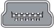
Note The 5-pin mini-Type B connectors resemble the 4-pin mini-Type B connectors. They are not compatible. Use only the 5-pin mini-Type B. See Figure 1-7.
Figure 1-7 USB Mini-Type B Port
 253163
The configurable inactivity timeout reactivates the RJ-45 console port if the USB-mini console port is activated, but no input activity occurs for a specified time period. When the USB-mini console port deactivates due to a timeout, you can restore its operation by disconnecting and reconnecting the USB cable. For information on using the CLI to configure the USB-mini console interface, see the switch software guide.
|
Catalyst 3560-C and 2960-C Switch Hardware Installation Guide |
1-10 |
OL-23803-02 |
Chapter 1 Product Overview
Front Panel
LEDs
You can use the switch system and port LEDs to monitor switch activity and performance.
Switch Panel LEDs
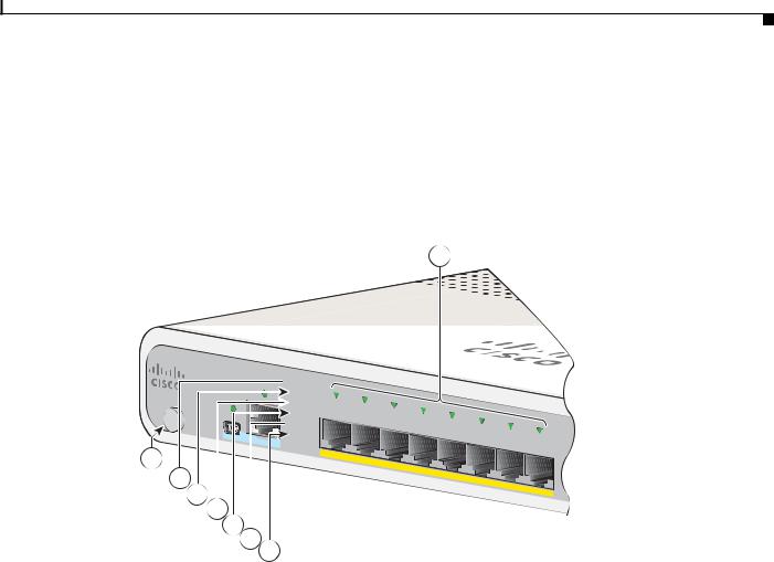
Figure 1-8 |
Switch LEDs |
8
M O D
1
 SYST
SYST
STAT
 DPLX
DPLX
SPD
 PoE
PoE
PD
2
3
4
5
6
7
PO W
ER
O VER
ETHERNET
5 6
282393
1 |
Mode button |
5 |
SPD LED (speed) |
|
|
|
|
2 |
SYST LED (system) |
6 |
PoE LED1 |
3 |
STAT LED (status) |
7 |
PD LED2 (powered device) |
4 |
DPLX LED (duplex) |
8 |
Port LEDs |
|
|
|
|
1.Applicable to switches with PoE ports.
2.Only the Catalyst 2960CPD-8PT-L and 3560PD-8PT-S switches have the PD LED.
|
|
Catalyst 3560-C and 2960-C Switch Hardware Installation Guide |
|
|
|
|
|
|
|||
|
OL-23803-02 |
|
|
1-11 |
|
|
|
|
|
||

Chapter 1 Product Overview
Front Panel
System LED
Table 1-4 |
System LED |
|
|
|
|
Color |
|
System Status |
|
|
|
Off |
|
System is not powered on. |
|
|
|
Green |
|
System is operating normally. |
|
|
|
Amber |
|
System is receiving power but is not operating properly. |
|
|
|
Console LEDs
The console LEDs show which console port is in use. See Figure 1-1 and Figure 1-2 for the LED locations.
If you connect a cable to a console port, the switch automatically uses that port for console communication. If you connect two console cables, the USB-mini console port has priority.
Table 1-5 |
RJ-45 and USB-Mini Console Port LEDs |
||
|
|
|
|
LED |
|
Color |
Description |
|
|
|
|
RJ-45 console port |
Green |
RJ-45 console port is active. |
|
|
|
|
USB-mini console port LED is not active. |
|
|
|
|
|
|
Off |
Port is not active. |
|
|
|
USB-mini console port is active. |
|
|
|
|
USB-mini console port |
Green |
USB-mini console port is active. |
|
|
|
|
RJ-45 console port LED is not active. |
|
|
|
|
|
|
Off |
Port is not active. |
|
|
|
RJ-45 console port is active. |
|
|
|
|
|
Catalyst 3560-C and 2960-C Switch Hardware Installation Guide |
1-12 |
OL-23803-02 |
Chapter 1 Product Overview
Front Panel
Modes for Port LEDs
The port LEDs, as a group or individually, display information about the switch and about the individual ports (Table 1-5).
Table 1-6 |
Modes for Port LEDs |
|
||
|
|
|
|
|
LED |
|
Port Mode |
|
Description |
|
|
|
|
|
STAT |
|
Port status |
|
The port status. This is the default mode. |
|
|
|
|
|
DUPLX |
|
Port duplex |
|
The port duplex mode: full duplex or half duplex. |
|
|
status |
|
|
|
|
|
|
|
SPD |
|
Port speed |
|
The port operating speed: 10, 100, or 1000 Mb/s. |
|
|
|
|
|
PD 1 |
|
Powered device |
|
The status of the uplink port. |
PoE |
|
PoE port power |
|
The PoE status. |
|
|
|
|
|
1. Only the Catalyst 2960CPD-8PT-L and 3560PD-8PT-S switches have the PD LED.
Port LEDs
RJ-45 ports and SFP-module slots have port LEDs. These LEDs, as a group or individually, provide information about the switch and about the individual ports.
Table 1-7 |
Meaning of Port LED Colors |
|
|
|
|
LED Color |
|
Meaning |
|
|
|
Off |
|
No link or port was administratively shut down. |
|
|
|
Green |
|
Link present but is not sending or receiving data. |
|
|
|
Blinking green |
|
Activity. Port is sending or receiving data. |
|
|
|
Alternating |
|
Link fault. Error frames can affect connectivity, and errors such as excessive |
green-amber |
|
collisions, CRC errors, and alignment and jabber errors are monitored for link |
|
|
faults. |
|
|
|
Amber |
|
Port is blocked by Spanning Tree Protocol (STP) and is not forwarding data. |
|
|
After a port is reconfigured, the port LED is amber for up to 30 seconds as STP |
|
|
searches for loops. |
|
|
|
|
|
Catalyst 3560-C and 2960-C Switch Hardware Installation Guide |
|
|
|
|
|
|
|||
|
OL-23803-02 |
|
|
1-13 |
|
|
|
|
|
||

Chapter 1 Product Overview
Front Panel
PoE LED
Even if the PoE mode is not selected, the LED shows PoE problems when they are detected (Table 1-8). The PoE LED is only on the switches that support PoE.
Table 1-8 |
PoE LED |
|
|
|
|
Color |
|
Meaning |
|
|
|
Off |
|
PoE is not enabled. |
|
|
|
Green |
|
PoE is enabled. Ports are functioning correctly. |
|
|
|
Blinking amber |
|
• PoE mode is not selected. |
|
|
• At least one of the 10/100 or 10/100/100 PoE ports has been |
|
|
denied power. |
|
|
or |
|
|
• At least one of the ports has a PoE fault. |
|
|
|
PD LED
Applies only to the Catalyst 2960CPD-8PT-L and 3560PD-8PT-S switches. (Table 1-9).
Table 1-9 |
PD LED |
|
|
|
|
Color |
|
Meaning |
|
|
|
Off |
|
Switch is not powered up. |
|
|
|
Blinking amber |
|
Switch is receiving power from a PoE device, but it is insufficient |
|
|
to power up the switch. |
|
|
|
Amber |
|
Switch is powered by only the auxiliary power adapter. |
|
|
|
Amber/green |
|
Switch is powered by the auxiliary power but is also receiving |
|
|
power from a PoE device. |
|
|
|
Green |
|
Switch is powered by a PoE switch through a PoE uplink port. |
|
|
|
Dual-Purpose Port LEDs
The dual-purpose port LEDs identify the connection as either a copper-based connector or an SFP module. The ports can autonegotiate, or you can manually configure each dual-purpose port as either 10/100/1000 with copper connectors or as an SFP-module port, but not as both types at the same time. See Table 1-7 for LED descriptions.
|
Catalyst 3560-C and 2960-C Switch Hardware Installation Guide |
1-14 |
OL-23803-02 |
Chapter 1 Product Overview
Rear Panel
Figure 1-9 Dual-Purpose LEDs
1 2
Catalyst 3560-CG Series PoE
8 


 3
3
9 |
10 |
7 |
4 |
6 5
208872
1 |
SFP module port LED |
5 |
RJ-45 port LED |
|
|
|
|
2 |
SFP module port LED |
6 |
RJ-45 port LED |
|
|
|
|
3 |
SFP module slot |
7 |
RJ-45 connector |
|
|
|
|
4 |
RJ-45 connector |
8 |
SFP module slot |
|
|
|
|
Rear Panel
•A reset button
•A security slot
•An AC power connector or a power adapter connector
•Heat sink fins (Catalyst 3560CG-8PC-S, 2960C-8PC-L, 2960C-12PC-L, 3560C-8PC-S, and 3560C-12PC-S switches)
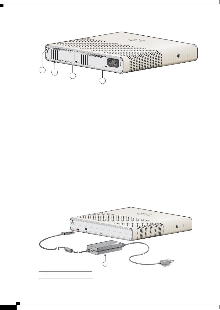
Figure 1-10 Catalyst 2960CPD-8PT-L Switch Rear Panel
RESET 
AUX 53V
1 2
3
208873
1 |
Security slot |
3 |
Power adapter connector |
|
|
|
|
2 |
Reset button |
|
|
|
|
|
|
|
|
Catalyst 3560-C and 2960-C Switch Hardware Installation Guide |
|
|
|
|
|
|
|||
|
OL-23803-02 |
|
|
1-15 |
|
|
|
|
|
||
Chapter 1 Product Overview
Rear Panel
Figure 1-11 Catalyst 3560CG-8PC-S Switch Rear Panel
RESET


1 2
3
4
208909
1 |
Security slot |
3 |
Heat sink fins |
|
|
|
|
2 |
Reset button |
4 |
AC power connector |
|
|
|
|
Internal Power Supply
All switches except the Catalyst 2960CPD-8TT-L, 2960CPD-8PT-L, and 3560CPD-8PT-S are powered through their internal power supplies. The internal power supply is an autoranging unit that supports input voltages between 100 and 240 VAC. Plug the AC power cord into the AC power connector and into an AC power outlet.
Auxiliary Power Adapter
The Catalyst 2960CPD-8TT-L, 2960CPD-8PT-L, and 3560CPD-8PT-S switches do not have a internal power supply. You can power the switch through either the 10/100/1000 uplink ports or through an auxiliary power adapter. You can order the auxiliary power adapter (PWR-ADPT) with the switch, or you can order it (PWR-ADPT=) later from your Cisco representative.
Figure 1-12 Connecting Through an External Auxiliary Power Adapter
RESET |
|
AUX 53V |
, 1.5A |
|
208870
1
1 Auxiliary power adapter
|
Catalyst 3560-C and 2960-C Switch Hardware Installation Guide |
1-16 |
OL-23803-02 |
Chapter 1 Product Overview
Management Options
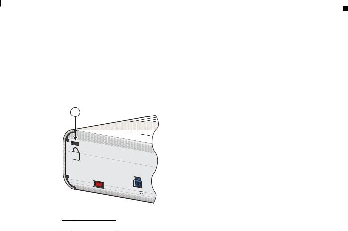
Security Slots
The switches have security slots on the rear panel. You can install an optional cable lock, such as the type that is used to secure a laptop computer, to secure the switch.
Figure 1-13 shows the slot on a rear panel.
Figure 1-13 Switch Left Panel
1
RESET |
|
AUX |
|
53V |
, 1.5A |
|
208875
1 Security slot
Reset Button
You can use press the reset button to power-cycle the switch. See Figure 1-13.
Management Options
•Cisco Network Assistant
Network Assistant is a PC-based network management GUI with centralized management of Cisco LAN switches, core switches, routers, access points, IP phones, and PIX firewalls.
Network Assistant is available at no cost and can be downloaded from this URL: http://www.cisco.com/en/US/products/ps5931/tsd_products_support_series_home.html
For information on starting Network Assistant, see the Getting Started with Cisco Network Assistant guide on Cisco.com. See the switch release notes for information on CNA support.
•Device manager
You can use the device manager, which is in the switch memory, to manage individual and standalone switches. Device manager is a web interface that offers quick configuration and monitoring. You can access the device manager from anywhere in your network through a web browser. For more information, see the device manager online help.
|
|
Catalyst 3560-C and 2960-C Switch Hardware Installation Guide |
|
|
|
|
|
|
|||
|
OL-23803-02 |
|
|
1-17 |
|
|
|
|
|
||

Chapter 1 Product Overview
Network Configurations
•Cisco IOS CLI
The switch CLI is based on Cisco IOS software and supports desktop-switching features. You can configure and monitor the switch and switch cluster members from the CLI. You can access the CLI either by connecting your management station directly to the switch console port or by using Telnet from a remote management station. See the switch command reference on Cisco.com for more information.
For setup instructions that use the CLI, go to Appendix C, “Configuring the Switch with the CLI Setup Program.”
•CiscoView application
The CiscoView device-management application displays the switch image that you can use to set configuration parameters and to view switch status and performance information. The CiscoView application, which you purchase separately, can be a standalone application or part of a Simple Network Management Protocol (SNMP) platform. See the CiscoView documentation for more information.
•SNMP network management
You can use SNMP management applications such as CiscoWorks LAN Management Solution (LMS) and HP OpenView to configure and manage the switch. You also can manage it from an SNMP-compatible workstation that is running platforms such as HP OpenView or SunNet Manager.
The Cisco Configuration Engine is a network management device that works with embedded CNS agents in the switch software. You can use the Cisco Configuration Engine to automate initial configurations and configuration updates on the switch.
Network Configurations
See the switch software configuration guide on Cisco.com for an explanation of network configuration concepts. The software configuration guide also provides network configuration examples for creating dedicated network segments that are interconnected through Ethernet connections.
|
Catalyst 3560-C and 2960-C Switch Hardware Installation Guide |
1-18 |
OL-23803-02 |

C H A P T E R 2
Switch Installation
This chapter describes how to start your switch and how to interpret the power-on self-test (POST) that ensures proper operation. It also describes how to install the switch.
Read the topics and perform the procedures in this order:
•Preparing for Installation, page 2-1
•Verifying Switch Operation, page 2-5
•Mounting the Switch, page 2-5
•Installing a Cover for the Reset Button (Optional), page 2-24
•Installing the Power Cord Retainer (Optional), page 2-25
•Installing the Cable Guard (Optional), page 2-28
•Connecting Devices to the Ethernet Ports, page 2-33
Preparing for Installation
•Warnings, page 2-1
•Installation Guidelines, page 2-3
•Equipment That You Supply, page 2-4
•Box Contents, page 2-4
•Powering the Switch, page 2-4
Warnings
These warnings are translated into several languages in the Regulatory Compliance and Safety Information for the Catalyst 3560-C and the 2960-C Switches guide.
Warning Before working on equipment that is connected to power lines, remove jewelry (including rings, necklaces, and watches). Metal objects will heat up when connected to power and ground and can cause serious burns or weld the metal object to the terminals. Statement 43
Catalyst 3560-C and 2960-C Switch Hardware Installation Guide
|
OL-23803-02 |
2-1 |
|
|
|

Chapter 2 Switch Installation
Preparing for Installation
Warning Read the wall-mounting instructions carefully before beginning installation. Failure to use the correct hardware or to follow the correct procedures could result in a hazardous situation to people and damage to the system. Statement 378
Warning Do not work on the system or connect or disconnect cables during periods of lightning activity.
Statement 1001
Warning Read the installation instructions before connecting the system to the power source. Statement 1004
Warning This product relies on the building’s installation for short-circuit (overcurrent) protection. Ensure that the protective device is rated not greater than:
20 A Statement 1005
Warning To prevent bodily injury when mounting or servicing this unit in a rack, you must take special precautions to ensure that the system remains stable. The following guidelines are provided to ensure your safety:
•This unit should be mounted at the bottom of the rack if it is the only unit in the rack.
•When mounting this unit in a partially filled rack, load the rack from the bottom to the top with the heaviest component at the bottom of the rack.
•If the rack is provided with stabilizing devices, install the stabilizers before mounting or servicing the unit in the rack. Statement 1006
Warning Class 1 laser product. Statement 1008
Warning This equipment must be grounded. Never defeat the ground conductor or operate the equipment in the absence of a suitably installed ground conductor. Contact the appropriate electrical inspection authority or an electrician if you are uncertain that suitable grounding is available. Statement 1024
Warning Ultimate disposal of this product should be handled according to all national laws and regulations.
Statement 1040
Catalyst 3560-C and 2960-C Switch Hardware Installation Guide
2-2 |
OL-23803-02 |
|
|
Loading...