


XFP-10GZR-OC192LR
Cisco XFP-10GZR-OC192LR, XFP-10GER-192IR+, XFP10GLR192SR-RGD, XFP-10GLR-OC192SR, DWDM-XFP-xxjcx Installation Notes
...
Cisco 10-Gigabit XFP Transceiver Modules
Installation Note
Revised: February 3, 2012
Product Numbers:
XFP-10G-MM-SR= XFP-10GLR-OC192SR= XFP10GLR-192SR-L=
XFP-10GER-OC192IR= XFP-10GER-192IR+= XFP10GER-192IR-L=
XFP-10GZR-OC192LR= DWDM-XFP-xx.xx= DWDM-XFP-C=
XFP10GLR192SR-RGD= XFP10GER192IR-RGD= XFP10GZR192LR-RGD=
This installation note provides the installation instructions for the 10-Gigabit XFP transceiver modules,
which are hot-swappable input/output (I/O) devices that plug into a 10-Gigabit port. The XFP transceiver
modules connect the system module port with a fiber-optic network.
This document contains these sections:
• Overview, page 2
• Safety, page 11
• Required Tools, page 17
• Installing the 10-Gigabit XFP Transceiver Module, page 17
• Removing the 10-Gigabit XFP Transceiver Module, page 19
• Translated Safety Warnings, page 21
• Related Documentation, page 26
• Obtaining Documentation and Submitting a Service Request, page 27
Americas Headquarters:
Cisco Systems, Inc., 170 West Tasman Drive, San Jose, CA 95134-1706 USA
Overview
3
4
144375
1
2
5
6
Overview
The 10-Gigabit XFP transceiver module is a hot-swappable I/O device that plugs into 10-Gigabit ports.
(See Figure 1.) The XFP transceiver module connects the electrical circuitry of the system with the
optical network.
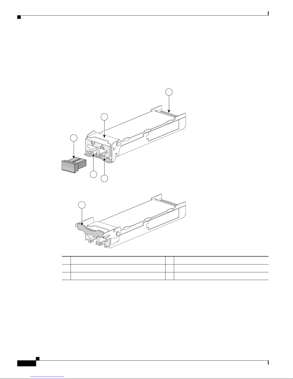
Figure 1 10-Gigabit XFP Transceiver Module
1 Transmit optical bore 4 Bail clasp (locked position)
2 Receive optical bore 5 Dust plug
3 Transceiver socket connector 6 Bail clasp (unlocked position)
The different XFP transceiver module types are listed in Table 1 and Table 2.
Cisco 10-Gigabit XFP Transceiver Modules Installation Note
2
OL-24246-01

Table 1 10-Gigabit XFP Transceiver Modules
Overview
XFP Transceiver Module
Description
Product Number
XFP-10G-MM-SR= Cisco 10GBASE-SR XFP transceiver module for MMF, 850-nm
wavelength, dual LC connector
XFP-10GLR-OC192SR=
XFP10GLR-192SR-L=
Cisco multirate XFP transceiver module for 10GBASE-LR Ethernet and
OC-192/STM-64 short-reach (SR-1) Packet-over-SONET/SDH (POS)
applications, SMF, dual LC connector
XFP10GLR192SR-RGD= Cisco multirate XFP transceiver module for 10GBASE-LR Ethernet and
OC-192/STM-64 short-reach (SR-1) Packet-over-SONET/SDH (POS)
applications, SMF, dual LC connector, industrial temperature range
XFP-10GER-OC192IR=
XFP-10GER-192IR+=
XFP10GER-192IR-L=
Cisco multirate XFP transceiver module for 10GBASE-ER Ethernet and
OC-192/STM-64 intermediate-reach (IR-2) Packet-over-SONET/SDH
(POS) applications, SMF, dual LC connector
XFP10GER192IR-RGD= Cisco multirate XFP transceiver module for 10GBASE-ER Ethernet and
OC-192/STM-64 intermediate-reach (IR-2) Packet-over-SONET/SDH
(POS) applications, SMF, dual LC connector, industrial temperature
range
XFP-10GZR-OC192LR= Cisco multirate XFP transceiver module for 10GBASE-LR Ethernet and
OC-192/STM-64 long-reach Packet-over-SONET/SDH (POS)
applications, SMF, dual LC connector
XFP10GZR192LR-RGD= Cisco multirate XFP transceiver module for 10GBASE-LR Ethernet and
OC-192/STM-64 long-reach Packet-over-SONET/SDH (POS)
applications, SMF, dual LC connector, industrial temperature range
Table 2 10-Gigabit Dense-Wavelength Division-Multiplexing (DWDM) XFP Transceiver
Modules
Transceiver Module
Product Number
Description ITU
Channel
DWDM-XFP-60.61= 10GBASE-DWDM 1560.61 nm XFP (100-GHz ITU grid) 21
DWDM-XFP-59.79= 10GBASE-DWDM 1559.79 nm XFP (100-GHz ITU grid) 22
DWDM-XFP-58.98= 10GBASE-DWDM 1558.98 nm XFP (100-GHz ITU grid) 23
DWDM-XFP-58.17= 10GBASE-DWDM 1558.17 nm XFP (100-GHz ITU grid) 24
DWDM-XFP-56.55= 10GBASE-DWDM 1556.55 nm XFP (100-GHz ITU grid) 26
DWDM-XFP-55.75= 10GBASE-DWDM 1555.75 nm XFP (100-GHz ITU grid) 27
DWDM-XFP-54.94= 10GBASE-DWDM 1554.94 nm XFP (100-GHz ITU grid) 28
DWDM-XFP-54.13= 10GBASE-DWDM 1554.13 nm XFP (100-GHz ITU grid) 29
DWDM-XFP-52.52= 10GBASE-DWDM 1552.52 nm XFP (100-GHz ITU grid) 31
DWDM-XFP-51.72= 10GBASE-DWDM 1551.72 nm XFP (100-GHz ITU grid) 32
DWDM-XFP-50.92= 10GBASE-DWDM 1550.92 nm XFP (100-GHz ITU grid) 33
DWDM-XFP-50.12= 10GBASE-DWDM 1550.12 nm XFP (100-GHz ITU grid) 34
DWDM-XFP-48.51= 10GBASE-DWDM 1548.51 nm XFP (100-GHz ITU grid) 36
OL-24246-01
Cisco 10-Gigabit XFP Transceiver Modules Installation Note
3

Overview
Table 2 10-Gigabit Dense-Wavelength Division-Multiplexing (DWDM) XFP Transceiver
Modules (continued)
Transceiver Module
Product Number
Description ITU
Channel
DWDM-XFP-47.72= 10GBASE-DWDM 1547.72 nm XFP (100-GHz ITU grid) 37
DWDM-XFP-46.92= 10GBASE-DWDM 1546.92 nm XFP (100-GHz ITU grid) 38
DWDM-XFP-46.12= 10GBASE-DWDM 1546.12 nm XFP (100-GHz ITU grid) 39
DWDM-XFP-44.53= 10GBASE-DWDM 1544.53 nm XFP (100-GHz ITU grid) 41
DWDM-XFP-43.73= 10GBASE-DWDM 1543.73 nm XFP (100-GHz ITU grid) 42
DWDM-XFP-42.94= 10GBASE-DWDM 1542.94 nm XFP (100-GHz ITU grid) 43
DWDM-XFP-42.14= 10GBASE-DWDM 1542.14 nm XFP (100-GHz ITU grid) 44
DWDM-XFP-40.56= 10GBASE-DWDM 1540.56 nm XFP (100-GHz ITU grid) 46
DWDM-XFP-39.77= 10GBASE-DWDM 1539.77 nm XFP (100-GHz ITU grid) 47
DWDM-XFP-38.98= 10GBASE-DWDM 1538.98 nm XFP (100-GHz ITU grid) 48
DWDM-XFP-38.19= 10GBASE-DWDM 1538.19 nm XFP (100-GHz ITU grid) 49
DWDM-XFP-36.61= 10GBASE-DWDM 1536.61 nm XFP (100-GHz ITU grid) 51
DWDM-XFP-35.82= 10GBASE-DWDM 1535.82 nm XFP (100-GHz ITU grid) 52
DWDM-XFP-35.04= 10GBASE-DWDM 1535.04 nm XFP (100-GHz ITU grid) 53
DWDM-XFP-34.25= 10GBASE-DWDM 1534.25 nm XFP (100-GHz ITU grid) 54
DWDM-XFP-32.68= 10GBASE-DWDM 1532.68 nm XFP (100-GHz ITU grid) 56
DWDM-XFP-31.90= 10GBASE-DWDM 1531.90 nm XFP (100-GHz ITU grid) 57
DWDM-XFP-31.12= 10GBASE-DWDM 1531.12 nm XFP (100-GHz ITU grid) 58
DWDM-XFP-30.33= 10GBASE-DWDM 1530.33 nm XFP (100-GHz ITU grid) 59
DWDM-XFP-C= 10GBASE-DWDM tuneable XFP (50-GHz ITU grid) See
Tabl e 3
Note The dual LC connector on the XFP transceivers support network interface cables with either Physical
Contact (PC) or Ultra-Physical Contact (UPC) polished face types. The dual LC connectors on the XFP
transceivers do not support network interface cables with an Angle Polished Connector (APC) polished
face type.
Tabl e 3 lists the 80 DWDM ITU 50-GHz channels available to the tuneable XFP transceiver modules.
Table 3 ITU 50-GHz Center Wavelengths and Channel Numbering
Channel ID Frequency
(THz)
Wavelength
(nm)
80 195.9 1530.33 79 195.85 1530.72
78 195.8 1531.12 77 195.75 1531.51
76 195.7 1531.90 75 195.65 1532.29
74 195.6 1532.68 73 195.55 1533.07
Cisco 10-Gigabit XFP Transceiver Modules Installation Note
4
Channel ID Frequency
(THz)
Wavelength
(nm)
OL-24246-01

Table 3 ITU 50-GHz Center Wavelengths and Channel Numbering (continued)
Overview
Channel ID Frequency
(THz)
Wavelength
(nm)
Channel ID Frequency
(THz)
Wavelength
(nm)
72 195.5 1533.47 71 195.45 1533.86
70 195.4 1534.25 69 195.35 1534.64
68 195.3 1535.04 67 195.25 1535.43
66 195.2 1535.82 65 195.15 1536.22
64 195.1 1536.61 63 195.05 1537.00
62 195.0 1537.40 61 194.95 1537.79
60 194.9 1538.19 59 194.85 1538.58
58 194.8 1538.98 57 194.75 1539.37
56 194.7 1539.77 55 194.65 1540.16
54 194.6 1540.56 53 194.55 1540.95
52 194.5 1541.35 51 194.45 1541.75
50 194.4 1542.14 49 194.35 1542.54
48 194.3 1542.94 47 194.25 1543.33
46 194.2 1543.73 45 194.15 1544.13
44 194.1 1544.53 43 194.05 1544.92
42 194.0 1545.32 41 193.95 154572
40 193.9 1546.12 39 193.85 1546.52
38 193.8 1546.92 37 193.75 1547.32
36 193.7 1547.72 35 193.65 1548.11
34 193.6 1548.51 33 193.55 1548.91
32 193.5 1549.32 31 193.45 1549.72
30 193.4 1550.12 29 193.35 1550.52
28 193.3 1550.92 27 193.25 1551.32
26 193.2 1551.72 25 193.15 1552.12
24 193.1 1552.52 23 193.05 1552.93
22 193.0 1553.33 21 192.95 1553.73
20 192.9 1554.13 19 192.85 1554.54
18 192.8 1554.94 17 192.75 1555.34
16 192.7 1555.75 15 192.65 1556.15
14 192.6 1556.55 13 192.55 1556.96
12 192.5 1557.36 11 192.45 1557.77
10 192.4 1558.17 9 192.35 1558.58
8 192.3 1558.98 7 192.25 1559.39
6 192.2 1559.79 5 192.15 1560.20
OL-24246-01
Cisco 10-Gigabit XFP Transceiver Modules Installation Note
5

Overview
Table 3 ITU 50-GHz Center Wavelengths and Channel Numbering (continued)
Channel ID Frequency
(THz)
Wavelength
(nm)
Channel ID Frequency
(THz)
Wavelength
(nm)
4 192.1 1560.61 3 192.05 1561.01
2 192.0 1561.42 1 191.95 1561.83
Tabl e 4 lists the port cabling specifications for the 10-Gigabit XFP transceiver modules.
Table 4 XFP Transceiver Port Cabling Specifications
XFP Product Number Nominal
Wavelength
(nm)
XFP-10G-MM-SR= 850 MMF 62.5
XFP-10GLR-OC192SR=
1310 SMF G.652 — 10 km (6.2 miles)
Cable Type Core Size
(microns)
62.5
50.0
50.0
50.0
Modal
Bandwidth
(MHz/km)
160
200
400
500
2000
XFP10GLR-192SR-L=
XFP10GLR192SR-RGD=
XFP-10GER-OC192IR=
1550 SMF G.652 — 40 km (24.86 miles)
XFP-10GER-192IR+=
XFP10GER-192IR-L=
XFP10GER192IR-RGD=
XFP-10GZR-OC192LR=
1550 SMF G.652 — 80 km (49.70 miles)
XFP10GZR192LR-RGD=
DWDM-XFP-xx.xx= See Tabl e 2
SMF G.652 — 80 km (49.70 miles)
on page 3
DWDM-XFP-C= See Tabl e 3
SMF G.652 — 80 km (49.70 miles)
on page 4
Maximum Cabling Distance
26 m (85.3 ft)
33 m (108.3 ft)
66 m (216.5 ft)
82 m (269 ft)
300 m (984.3 ft)
10-Gigabit Ethernet
2 km (1.24 miles)
OC-192/STM-64 SR1
Cisco 10-Gigabit XFP Transceiver Modules Installation Note
6
OL-24246-01

Tabl e 5 lists the XFP transceiver modules optical transmit and receive specifications.
Table 5 XFP Transceiver Optical Transmit and Receive Specifications
Overview
XFP Product Number Transceiver Operating Mode Transmit Power
(dBm)
XFP-10G-MM-SR= 10GBASE-SR, 850-nm MMF
(10.3125-Gbps line rate)
XFP-10GLR-OC192SR=
XFP10GLR-192SR-L=
XFP10GLR192SR-RGD=
10GBASE-LR, 1310-nm SMF
(10.3125-Gbps line rate)
OC-192/STM-64 SR1, 1310-nm
SMF
–1.0 (Max)
–7.3 (Min)
+0.5 (Max)
–8.2 (Min)
–1.0 (Max)
–6.0 (Min)
(9.95328-Gbps line rate)
XFP-10GER-OC192IR=
XFP-10GER-192IR+=
XFP10GER-192IR-L=
10GBASE-ER, 1550-nm SMF
(10.3125-Gbps line rate)
+4.0 (Max)
–4.7 (Min)
XFP10GER192IR-RGD=
OC-192/STM-64 IR2, 1550-nm
SMF
+2.0 (Max)
–1.0 (Min)
(9.95328-Gbps line rate)
XFP-10GZR-OC192LR=
XFP10GZR192LR-RGD=
10GBASE-ZR, 1550-nm SMF
(10.3125-Gbps line rate)
+4.0 (Max)
0 (Min)
OC-192/STM-64 LR2, 1550-nm
SMF
(9.95328-Gbps line rate)
Receive Power
(dBm)
–1.2 (Max)
–9.9 (Min)
+0.5 (Max)
–14.4 (Min)
–1.0 (Max)
–11.0 (Min)
–1.0 (Max)
–15.8 (Min)
+2.0 (Max)
–14.0 (Min
–7.0 (Max)
–24 (Min)
Transmit and
Receive
Wavelength (nm)
840 to 860
(TX and RX)
1260 to 1355 (TX)
1260 to 1565 (RX)
1290 to 1330 (TX)
1260 to 1565 (RX)
1530 to 1565 (TX)
1260 to 1565 (RX)
1530 to 1565 (TX)
1260 to 1565 (RX)
1530 to 1565 (TX)
1260 to 1565 (RX)
OL-24246-01
Cisco 10-Gigabit XFP Transceiver Modules Installation Note
7

Overview
Tabl e 6 lists the optical specifications of the DWDM XFP transceiver modules.
Table 6 DWDM XFP Optical Transmit and Receive Specifications
Parameter Symbol Minimum Typical Maximum Units Notes and Conditions
Transmitter
Spectral Width — — — 0.2 nm Full width, –20 dB from maximum, with
resolution bandwidth (RBW) = 0.01 nm
Transmitter
—x
1
– 100
xx
1
+ 100 pm See Tabl e 2 for center wavelengths
center
wavelength
Side-mode
SMSR 30 — — dB —
suppression ratio
Transmitter
OMI 9 — — dB —
extinction ratio
Transmitter
optical output
Pout –1.0 — 3.0 dBm Average power coupled into single-mode
fiber
power
Receiver
Receiver optical
— 1530— 1565nm —
input wavelength
Receiver damage
—— —4.0 dBm—
threshold
Dispersion
— –500— 1600ps/nm—
tolerance
Power-Limited Performance (measured at optical signal-to-noise ratio [OSNR] of 30 dB at 0.1-nm RBW)
Optical input
power
Dispersion power
penalty
Pin –23.0 — –7.0 dBm Measured at a bit error rate (BER) = 1E–12
with an IEEE 802.3 test pattern
— — — 3 dB Measured at a bit error rate (BER) = 1E–12
with an IEEE 802.3 test pattern
Noise-Limited Performance (measured at OSNR of 24 dB at 0.1-nm RBW)
Optical input
power
Dispersion
OSNR penalty
1. x is the center wavelength. The center wavelength can vary ±100 picometers (pm).
Pin –18.0 — –7.0 dB Measured at a bit error rate (BER) = 1E–12
with an IEEE 802.3 test pattern
— — — 3 dB Measured at a bit error rate (BER) = 1E–12
with an IEEE 802.3 test pattern
Cisco 10-Gigabit XFP Transceiver Modules Installation Note
8
OL-24246-01

Overview
Tabl e 7 and Tab le 8 list the optical specifications of the tuneable DWDM XFP transceiver modules
(DWDM-XFP-C=).
Table 7 Tuneable DWDM XFP Optical Transmit and Receive Specifications
Parameter Symbol Minimum Typical Maximum Units Notes and Conditions
Transmitter
Spectral Width — — — 0.2 nm Full width, –20 dB from maximum, with
resolution bandwidth (RBW) = 0.01 nm.
Transmitter
—x
1
– 25
xx
1
+ 25 pm See Tab le 2 for center wavelengths.
center
wavelength
Side-mode
SMSR 30 — — dB —
suppression ratio
Transmitter
OMI 9 — — dB —
extinction ratio
Transmitter
optical output
Pout 0.0 — 3.0 dBm Average power coupled into single-mode
fiber
power
Receiver
Receiver optical
— 1530— 1565nm —
input wavelength
Receiver damage
—— —4.0 dBm—
threshold
Dispersion
— –500— 1600ps/nm—
tolerance
Power-Limited Performance (measured at optical signal-to-noise ratio [OSNR] of 30 dB at 0.1-nm RBW)
Optical input
power
Dispersion power
penalty
Pin –23.0 — –7.0 dBm Measured at a bit error rate (BER) = 1E–12
with an IEEE 802.3 test pattern
— — — 3 dB Measured at a bit error rate (BER) = 1E–12
with an IEEE 802.3 test pattern
Noise-Limited Performance (measured at OSNR of 24 dB at 0.1-nm RBW)
Optical input
power
Dispersion
OSNR penalty
1. x is the center wavelength. The center wavelength can vary ±25 picometers (pm).
Pin –18.0 — –7.0 dB Measured at a bit error rate (BER) = 1E–12
with an IEEE 802.3 test pattern
— — — 3 dB Measured at a bit error rate (BER) = 1E–12
with an IEEE 802.3 test pattern
OL-24246-01
Cisco 10-Gigabit XFP Transceiver Modules Installation Note
9
 Loading...