


 Loading...
Catalyst 2960 Switch Hardware
Installation Guide
March 2010
Revised: April 2013
Americas Headquarters
Cisco Systems, Inc. 170 West Tasman Drive
San Jose, CA 95134-1706 USA http://www.cisco.com Tel: 408 526-4000
800 553-NETS (6387) Fax: 408 527-0883
Text Part Number: OL-7075-09
THE SPECIFICATIONS AND INFORMATION REGARDING THE PRODUCTS IN THIS MANUAL ARE SUBJECT TO CHANGE WITHOUT NOTICE. ALL STATEMENTS, INFORMATION, AND RECOMMENDATIONS IN THIS MANUAL ARE BELIEVED TO BE ACCURATE BUT ARE PRESENTED WITHOUT WARRANTY OF ANY KIND, EXPRESS OR IMPLIED. USERS MUST TAKE FULL RESPONSIBILITY FOR THEIR APPLICATION OF ANY PRODUCTS.
THE SOFTWARE LICENSE AND LIMITED WARRANTY FOR THE ACCOMPANYING PRODUCT ARE SET FORTH IN THE INFORMATION PACKET THAT SHIPPED WITH THE PRODUCT AND ARE INCORPORATED HEREIN BY THIS REFERENCE. IF YOU ARE UNABLE TO LOCATE THE SOFTWARE LICENSE OR LIMITED WARRANTY, CONTACT YOUR CISCO REPRESENTATIVE FOR A COPY.
The following information is for FCC compliance of Class A devices: This equipment has been tested and found to comply with the limits for a Class A digital device, pursuant to part 15 of the FCC rules. These limits are designed to provide reasonable protection against harmful interference when the equipment is operated in a commercial environment. This equipment generates, uses, and can radiate radio-frequency energy and, if not installed and used in accordance with the instruction manual, may cause harmful interference to radio communications. Operation of this equipment in a residential area is likely to cause harmful interference, in which case users will be required to correct the interference at their own expense.
The following information is for FCC compliance of Class B devices: The equipment described in this manual generates and may radiate radio-frequency energy. If it is not installed in accordance with Cisco’s installation instructions, it may cause interference with radio and television reception. This equipment has been tested and found to comply with the limits for a Class B digital device in accordance with the specifications in part 15 of the FCC rules. These specifications are designed to provide reasonable protection against such interference in a residential installation. However, there is no guarantee that interference will not occur in a particular installation.
Modifying the equipment without Cisco’s written authorization may result in the equipment no longer complying with FCC requirements for Class A or Class B digital devices. In that event, your right to use the equipment may be limited by FCC regulations, and you may be required to correct any interference to radio or television communications at your own expense.
You can determine whether your equipment is causing interference by turning it off. If the interference stops, it was probably caused by the Cisco equipment or one of its peripheral devices. If the equipment causes interference to radio or television reception, try to correct the interference by using one or more of the following measures:
•Turn the television or radio antenna until the interference stops.
•Move the equipment to one side or the other of the television or radio.
•Move the equipment farther away from the television or radio.
•Plug the equipment into an outlet that is on a different circuit from the television or radio. (That is, make certain the equipment and the television or radio are on circuits controlled by different circuit breakers or fuses.)
Modifications to this product not authorized by Cisco Systems, Inc. could void the FCC approval and negate your authority to operate the product.
The Cisco implementation of TCP header compression is an adaptation of a program developed by the University of California, Berkeley (UCB) as part of UCB’s public domain version of the UNIX operating system. All rights reserved. Copyright © 1981, Regents of the University of California.
NOTWITHSTANDING ANY OTHER WARRANTY HEREIN, ALL DOCUMENT FILES AND SOFTWARE OF THESE SUPPLIERS ARE PROVIDED “AS IS” WITH ALL FAULTS. CISCO AND THE ABOVE-NAMED SUPPLIERS DISCLAIM ALL WARRANTIES, EXPRESSED OR IMPLIED, INCLUDING, WITHOUT LIMITATION, THOSE OF MERCHANTABILITY, FITNESS FOR A PARTICULAR PURPOSE AND NONINFRINGEMENT OR ARISING FROM A COURSE OF DEALING, USAGE, OR TRADE PRACTICE.
IN NO EVENT SHALL CISCO OR ITS SUPPLIERS BE LIABLE FOR ANY INDIRECT, SPECIAL, CONSEQUENTIAL, OR INCIDENTAL DAMAGES, INCLUDING, WITHOUT LIMITATION, LOST PROFITS OR LOSS OR DAMAGE TO DATA ARISING OUT OF THE USE OR INABILITY TO USE THIS MANUAL, EVEN IF CISCO OR ITS SUPPLIERS HAVE BEEN ADVISED OF THE POSSIBILITY OF SUCH DAMAGES.
Cisco and the Cisco logo are trademarks or registered trademarks of Cisco and/or its affiliates in the U.S. and other countries. To view a list of Cisco trademarks, go to this URL: www.cisco.com/go/trademarks. Third-party trademarks mentioned are the property of their respective owners. The use of the word partner does not imply a partnership relationship between Cisco and any other company. (1110R)
Any Internet Protocol (IP) addresses used in this document are not intended to be actual addresses. Any examples, command display output, and figures included in the document are shown for illustrative purposes only. Any use of actual IP addresses in illustrative content is unintentional and coincidental.
Catalyst 2960 Switch Hardware Installation Guide
© 2005–2010 Cisco Systems, Inc. All rights reserved.

|
|
|
|
|
|
C O N T E N T S |
|||||
|
|
Preface vii |
|
|
|
|
|
|
|
|
|
|
Product Overview |
|
|
|
|
|
|
|
|
||
C H A P T E R 1 |
1-1 |
|
|
|
|
|
|
|
|||
|
|
Features |
1-1 |
|
|
|
|
|
|
|
|
|
|
Front Panel Description |
1-4 |
|
|
|
|
|
|
||
|
|
Catalyst 2960 Switch 24and 48-Port Switches |
1-4 |
|
|
|
|
||||
|
|
Catalyst 2960-24-S, 2960-Plus 24TC-S, 2960-24TC-S, 2960-Plus 48TC-S, 2960-48TC-S, and |
|||||||||
|
|
2960-48TT-S Switches |
1-5 |
|
|
|
|
|
|||
|
|
Catalyst 2960-Plus 24PC-L, 2960-24PC-L, 2960-Plus 24PC-S, 2960-24PC-S, 2960-Plus 24LC-L, |
|||||||||
|
|
2960-Plus 24LC-S, 2960-24LC-S, 2960-Plus 24TC-L, 2960-24TC-L, 2960-Plus 48TC-L, |
|||||||||
|
|
2960-48TC-L, 2960-24LT-L, 2960-24TT-L, 2960-48TT-L, 2960-Plus 48PST-L, 2960-48PST-L, |
|||||||||
|
|
2960-Plus 48PST-S, and 2960-48PST-S Switches |
1-6 |
|
|
|
|||||
|
|
Catalyst 2960G-24TC-L and Catalyst 2960G-48TC-L Switches 1-9 |
|||||||||
|
|
Catalyst 2960 8-Port Switches 1-9 |
|
|
|
|
|
||||
|
|
Catalyst 2960PD-8TT-L Switch 1-9 |
|
|
|
|
|
||||
|
|
Catalyst 2960-8TC-S, Catalyst 2960-8TC-L, and Catalyst 2960G-8TC -L Switches 1-10 |
|||||||||
|
|
10/100 Ports |
1-11 |
|
|
|
|
|
|
|
|
|
|
10/100/1000 Ports |
1-11 |
|
|
|
|
|
|
||
|
|
PoE Ports (Only Catalyst 2960 PoE Switches) 1-12 |
|
|
|
|
|||||
|
|
SFP Module Slots |
1-13 |
|
|
|
|
|
|
||
|
|
Dual-Purpose Port |
1-13 |
|
|
|
|
|
|
||
|
|
Power Input Port (Catalyst 2960PD-8TT-L Switch) |
1-14 |
|
|
|
|||||
|
|
LEDs |
1-14 |
|
|
|
|
|
|
|
|
|
|
System LED 1-15 |
|
|
|
|
|
|
|||
|
|
RPS LED |
1-16 |
|
|
|
|
|
|
|
|
|
|
Port LEDs and Modes |
1-16 |
|
|
|
|
|
|||
|
|
Dual-Purpose Port LEDs |
1-18 |
|
|
|
|
|
|||
|
|
Cable Guard for the Catalyst 2960 8-Port Switches |
1-19 |
|
|
|
|||||
|
|
Rear Panel Description |
1-19 |
|
|
|
|
|
|
||
|
|
Internal Power Supply 1-20 |
|
|
|
|
|
|
|||
|
|
Cisco RPS 1-20 |
|
|
|
|
|
|
|
||
|
|
Cisco RPS 2300 |
1-20 |
|
|
|
|
|
|
||
|
|
Cisco RPS 675 |
1-21 |
|
|
|
|
|
|
||
|
|
Console Port |
1-21 |
|
|
|
|
|
|
|
|
|
|
Security Slots |
1-21 |
|
|
|
|
|
|
|
|
|
|
|
|
|
|
Catalyst 2960 Switch Hardware Installation Guide |
|
|
|
||
|
|
|
|
|
|
|
|||||
|
OL-7075-09 |
|
|
|
|
|
|
|
|
iii |
|
|
|
|
|
|
|
|
|
|
|
||

Contents
|
Management Options |
1-22 |
|
|
Network Configurations |
1-22 |
|
|
Switch Installation (24and 48-Port Switches) 2-1 |
||
C H A P T E R 2 |
|||
|
Preparing for Installation 2-1 |
||
|
Warnings 2-2 |
|
|
|
Guidelines for Particulate Matter 2-4 |
||
|
Installation Guidelines |
2-4 |
|
|
Box Contents 2-5 |
|
|
|
Tools and Equipment |
2-5 |
|
|
Verifying Switch Operation |
2-5 |
|
|
Installing the Switch |
2-6 |
|
Rack-Mounting 2-6
Removing Screws from the Switch 2-7
Attaching Brackets to the Catalyst 2960 Switch 2-7
Mounting the Switch in a Rack
Attaching the Cable Guide
Wall-Mounting 2-11
Attaching the Brackets to the Switch for Wall-Mounting 2-12
Attaching the RPS Connector Cover
Mounting the Switch on a Wall
Tableor Shelf-Mounting 2-14
Connecting to the 10/100 and 10/100/1000
Installing and Removing SFP Modules
Installing SFP Modules
Removing SFP Modules
Connecting to SFP Modules 2-18
Connecting to Fiber-Optic SFP Modules
Connecting to 1000BASE-T SFP Modules
Connecting to a Dual-Purpose Port
Where to Go Next
Catalyst 2960 Switch Hardware Installation Guide
|
iv |
OL-7075-09 |
|
|
|

Contents
C H A P T E R 3 |
Switch Installation (8-Port Switches) 3-1 |
||
|
Preparing for Installation |
3-1 |
|
|
Warnings 3-1 |
|
|
|
Installation Guidelines |
3-3 |
|
|
Equipment That You Supply 3-4 |
||
|
Box Contents 3-5 |
|
|
|
Tools and Equipment |
3-5 |
|
|
Verifying Switch Operation |
3-5 |
|
|
Installing the Switch |
3-5 |
|
|
Deskor Shelf-Mounting (without Mounting Screws) 3-6 |
||
|
Deskor Shelf-Mounting (with Mounting Screws) 3-7 |
||
|
Under the Deskor Shelf-Mounting (with Mounting Screws) 3-8 |
||
|
Wall-Mounting (with Mounting Screws) 3-11 |
||
|
Magnet Mounting |
3-14 |
|
|
Rack-Mounting 3-15 |
|
|
|
|
|
|
Attaching Brackets to the Switch |
3-15 |
|
|||
|
Mounting the Switch in a 19-Inch Rack |
3-16 |
||||
|
Wall-Mounting (with Rack-Mount Brackets) |
3-16 |
||||
|
Where to Go Next |
3-18 |
|
|
|
|
|
Troubleshooting 4-1 |
|
|
|
|
|
C H A P T E R 4 |
|
|
|
|
|
|
|
Diagnosing Problems |
4-1 |
|
|
|
|
|
Verify Switch POST Results |
4-2 |
|
|
|
|
|
Monitor Switch LEDs 4-2 |
|
|
|
|
|
|
Verify Switch Connections |
4-2 |
|
|
|
|
|
Bad or Damaged Cable |
4-2 |
|
|
|
|
|
Ethernet and Fiber Cables |
4-3 |
|
|
||
|
Link Status |
4-3 |
|
|
|
|
|
Transceiver Module Port Issues |
4-3 |
|
|||
|
Port and Interface Settings |
4-4 |
|
|
||
|
Ping the End Device |
4-4 |
|
|
|
|
|
Spanning Tree Loops |
4-4 |
|
|
|
|
Monitor Switch Performance 4-4
|
Speed, Duplex, and Autonegotiation |
4-4 |
|
|
|
|
Autonegotiation and NIC Cards 4-5 |
|
|
|
|
|
Cabling Distance 4-5 |
|
|
|
|
|
Clearing the Switch IP Address and Configuration 4-5 |
||||
|
Locating the Switch Serial Number 4-6 |
|
|
|
|
|
|
Catalyst 2960 Switch Hardware Installation Guide |
|
|
|
|
|
|
|||
|
OL-7075-09 |
|
|
v |
|
|
|
|
|
||

Contents
A P P E N D I X A |
Technical Specifications |
A-1 |
|
|
|
|
|
||
|
|
Connector and Cable Specifications |
|
|
|
|
|||
A P P E N D I X |
B |
B-1 |
|
|
|
||||
|
|
Connector Specifications |
B-1 |
|
|
|
|
|
|
|
|
10/100/1000 Ports |
B-1 |
|
|
|
|
|
|
|
|
Connecting to 10BASE-T- and 100BASE-TX-Compatible Devices B-1 |
|||||||
|
|
Connecting to 1000BASE-T Devices |
|
B-2 |
|
||||
|
|
SFP Module Ports |
B-3 |
|
|
|
|
|
|
|
|
Dual-Purpose Ports |
B-3 |
|
|
|
|
|
|
|
|
Console Port |
B-4 |
|
|
|
|
|
|
|
|
Cable and Adapter Specifications B-4 |
|
|
|
||||
|
|
SFP Module Cable Specifications |
B-4 |
|
|
|
|||
|
|
Two Twisted-Pair Cable Pinouts |
B-6 |
|
|
|
|||
|
|
Four Twisted-Pair Cable Pinouts for 1000BASE-T Ports |
B-6 |
||||||
|
|
Crossover Cable and Adapter Pinouts |
B-7 |
|
|||||
|
|
Identifying a Crossover Cable B-7 |
|
|
|
||||
|
|
Adapter Pinouts |
B-8 |
|
|
|
|
|
|
|
|
Configuring the Switch with the CLI-Based Setup Program |
|
||||||
A P P E N D I X |
C |
C-1 |
|||||||
|
|
Accessing the CLI |
C-1 |
|
|
|
|
|
|
|
|
Accessing the CLI Through Express Setup |
C-1 |
|
|||||
|
|
Accessing the CLI Through the Console Port C-2 |
|
||||||
|
|
Connecting to the Console Port |
C-3 |
|
|
|
|
||
|
|
Starting the Terminal Emulation Software |
C-3 |
|
|||||
|
|
Connecting to a Power Source |
C-4 |
|
|
|
|
||
|
|
Entering the Initial Configuration Information |
C-4 |
|
|||||
|
|
IP Settings |
C-5 |
|
|
|
|
|
|
|
|
Completing the Setup Program |
C-5 |
|
|
|
|||
I N D E X
Catalyst 2960 Switch Hardware Installation Guide
|
vi |
OL-7075-09 |
|
|
|

Preface
Audience
This guide is for the networking or computer technician responsible for installing the
Catalyst 2960 switch, hereafter known as the switch. We assume that you are familiar with the concepts and terminology of Ethernet and local area networking. If you are interested in more training and education in these areas, learning opportunities including training courses, self-study options, seminars, and career certifications programs are available on the Cisco Training & Events web page:
http://www.cisco.com/web/learning/index.html
Purpose
This guide describes the hardware features of the Catalyst 2960 switch. It describes the physical and performance characteristics of the switch, explains how to install it, and provides troubleshooting information.
This guide does not describe system messages that you might receive or how to configure your switch. For more information, see the switch software configuration guide, the switch command reference, and the switch system message guide on the Cisco.com Product Documentation home page. For information about the standard Cisco IOS Release 12.1 or 12.2 commands, see the Cisco IOS documentation set from the Cisco.com home page by choosing Support > Documentation > Product and Support Documentation/Cisco IOS Software.
Conventions
This document uses these conventions and symbols for notes, cautions, and warnings:
Note Means reader take note. Notes contain helpful suggestions or references to materials not contained in this manual.
Caution Means reader be careful. In this situation, you might do something that could result in equipment damage or loss of data.
Catalyst 2960 Switch Hardware Installation Guide
|
OL-7075-09 |
vii |
|

Preface
Warning IMPORTANT SAFETY INSTRUCTIONS
This warning symbol means danger. You are in a situation that could cause bodily injury. Before you work on any equipment, be aware of the hazards involved with electrical circuitry and be familiar with standard practices for preventing accidents. Use the statement number provided at the end of each warning to locate its translation in the translated safety warnings that accompanied this device. Statement 1071
SAVE THESE INSTRUCTIONS
The safety warnings for this product are translated into several languages in the Regulatory Compliance and Safety Information for the Catalyst 2960 Switch guide. The EMC regulatory statements are also included in that guide.
Related Documentation
These documents provide complete information about the switch and are available from this
Cisco.com site:
http://www.cisco.com/en/US/products/ps6406/tsd_products_support_series_home.html
•Release Notes for the Catalyst 3750, 3560, 2970, and 2960 Switches
Note Before installing, configuring, or upgrading the switch, refer to the release notes on Cisco.com for the latest information.
•Catalyst 2960 Switch Software Configuration Guide
•Catalyst 2960 Switch Command Reference
•Catalyst 3750, 3560, 3550, 2970, and 2960 Switch System Message Guide
•Device manager online help (available on the switch)
•Cisco Network Assistant online help (available on the switch)
•Catalyst 2960 Switches Getting Started Guide (8-Port Switches)
•Catalyst 2960 Switch Getting Started Guide. This guide is for the 24and 48-port switches and provides information in these languages: English, Chinese (Simplified), French, German, Italian, Japanese, and Spanish
•Regulatory Compliance and Safety Information for the Catalyst 2960 Switch
For information about related products, see these documents on Cisco.com:
•Getting Started with Cisco Network Assistant
•Release Notes for Cisco Network Assistant
•Cisco Small Form-Factor Pluggable Modules Installation Notes
•Cisco CWDM GBIC and CWDM SFP Installation Note
Catalyst 2960 Switch Hardware Installation Guide
|
viii |
OL-7075-09 |
|
|
|

Preface
•Cisco Redundant Power System 2300 Hardware Installation Guide
•Cisco RPS 675 Redundant Power System Hardware Installation Guide
These compatibility matrix documents are available from this Cisco.com site: http://www.cisco.com/en/US/products/hw/modules/ps5455/products_device_support_tables_list.html
•Cisco Gigabit Ethernet Transceiver Modules Compatibility Matrix
•Cisco 100-Megabit Ethernet SFP Modules Compatibility Matrix
•Cisco CWDM SFP Transceiver Compatibility Matrix
•Cisco Small Form-Factor Pluggable Modules Compatibility Matrix
•Compatibility Matrix for 1000BASE-T Small Form-Factor Pluggable Modules
•Cisco Redundant Power System 2300 Compatibility Matrix
Obtaining Documentation and Submitting a Service Request
For information on obtaining documentation, submitting a service request, and gathering additional information, see the monthly What’s New in Cisco Product Documentation, which also lists all new and revised Cisco technical documentation, at:
http://www.cisco.com/en/US/docs/general/whatsnew/whatsnew.html
Subscribe to the What’s New in Cisco Product Documentation as a Really Simple Syndication (RSS) feed and set content to be delivered directly to your desktop using a reader application. The RSS feeds are a free service and Cisco currently supports RSS Version 2.0.
Catalyst 2960 Switch Hardware Installation Guide
|
OL-7075-09 |
ix |
|

Preface
Catalyst 2960 Switch Hardware Installation Guide
|
x |
OL-7075-09 |
|
|
|
C H A P T E R 1
Product Overview
The Catalyst 2960 switch—also referred to as the switch—is an Ethernet switch to which you can connect devices such as workstations, Cisco Wireless Access Points, Cisco IP Phones, and other network devices including servers, routers, and other switches. This chapter provides a functional overview of the Catalyst 2960 switch. These topics are included:
•Features, page 1-1
•Front Panel Description, page 1-4
•Rear Panel Description, page 1-19
•Management Options, page 1-22
Features
You can deploy the 24and 48-port Catalyst 2960 switches as backbone switches, aggregating 10BASE-T, 100BASE-TX, and 1000BASE-T Ethernet traffic from other network devices. The Catalyst 2960 8-port compact switches provide the same Ethernet connectivity, but you can deploy these switches outside of the traditional wiring closet environment, such as in office workspaces and classrooms. See the switch software configuration guide for deployment examples.
Table 1-1 describes the switch model features.
Table 1-1 |
Catalyst 2960 Switch Model Descriptions |
|||||||
|
|
|
|
|
|
|
|
|
|
|
|
Supported |
|
|
|
|
|
|
Switch Model |
|
Software Image |
Description |
||||
|
|
|
|
|||||
|
Catalyst 2960-8TC-S |
LAN-Lite |
8 10/100BASE-TX Ethernet ports and 1 dual-purpose port |
|||||
|
|
|
|
(1 10/100/1000BASE-T copper port and 1 small form-factor pluggable |
||||
|
|
|
|
[SFP] module slot); (no fan or RPS port) |
||||
|
|
|
|
|
||||
|
Catalyst 2960-24-S |
LAN-Lite |
24 |
10/100BASE-TX Ethernet ports (no RPS port or SFP module slot) |
||||
|
|
|
|
|
||||
|
Catalyst 2960-Plus 24TC-S |
LAN-Lite |
24 |
10/100BASE-TX Ethernet ports and 2 dual-purpose ports (no RPS port) |
||||
|
|
|
|
|
||||
|
Catalyst 2960-24TC-S |
LAN-Lite |
24 |
10/100BASE-TX Ethernet ports and 2 dual-purpose ports (no RPS port) |
||||
|
|
|
|
|
||||
|
Catalyst 2960-Plus 48TC-S |
LAN-Lite |
48 |
10/100BASE-TX Ethernet ports and 2 dual-purpose ports (no RPS port) |
||||
|
|
|
|
|
||||
|
Catalyst 2960-48TC-S |
LAN-Lite |
48 |
10/100BASE-TX Ethernet ports and 2 dual-purpose ports (no RPS port) |
||||
|
|
|
|
|
||||
|
Catalyst 2960-48TT-S |
LAN Lite |
48 |
10/100BASE-TX ports and 2 10/100/1000 ports (no RPS port or |
||||
|
|
|
|
SFP module slot) |
||||
|
|
|
|
|
|
|
|
|
|
|
|
|
|
Catalyst 2960 Switch Hardware Installation Guide |
|
|
|
|
|
|
|
|
|
|||
|
OL-7075-09 |
|
|
|
|
|
1-1 |
|
|
|
|
|
|
|
|
||

Chapter 1 Product Overview
Features
Table 1-1 |
Catalyst 2960 Switch Model Descriptions (continued) |
|||
|
|
|
|
|
|
|
Supported |
|
|
Switch Model |
|
Software Image |
Description |
|
|
|
|
||
Catalyst 2960-Plus 48PST-S |
LAN-Lite |
48 10/100B SE-TX PoE ports, 2 10/100/1000 ports, and 2 SFP module slots |
||
|
|
|
||
Catalyst 2960-48PST-S |
LAN-Lite |
48 10/100BASE-TX PoE ports, 2 10/100/1000 ports, and 2 SFP module slots |
||
|
|
|
|
|
Catalyst 2960-Plus 24PC-S |
LAN-Lite |
24 |
10/100BASE-TX PoE ports and 2 dual-purpose ports |
|
|
|
|
|
|
Catalyst 2960-24PC-S |
LAN-Lite |
24 |
10/100BASE-TX PoE ports and 2 dual-purpose ports |
|
|
|
|
|
|
Catalyst 2960-Plus 24LC-S |
LAN-Lite |
24 |
10/100BASE-TX ports (8 of which are PoE) and 2 dual-purpose ports |
|
|
|
|
|
|
Catalyst 2960-24LC-S |
LAN-Lite |
24 |
10/100BASE-TX ports (8 of which are PoE) and 2 dual-purpose ports |
|
|
|
|
||
Catalyst 2960-8TC-L |
LAN-Base |
8 10/100BASE-TX Ethernet ports and 1 dual-purpose port (no fan or |
||
|
|
|
RPS port) |
|
|
|
|
||
Catalyst 2960G-8TC-L |
LAN-Base |
7 10/100/100BASE-TX Ethernet ports and 1 dual-purpose port (no fan or |
||
|
|
|
RPS port) |
|
|
|
|
||
Catalyst 2960PD-8TT-L |
LAN-Base |
8 10/100BASE-TX Ethernet ports and 1 10/100/1000 port that receives |
||
|
|
|
power (no fan, RPS port, or SFP module slot) |
|
|
|
|
|
|
Catalyst 2960-24LT-L |
LAN-Base |
24 |
10/100BASE-TX ports, 8 of which are Power over Ethernet (PoE), and |
|
|
|
|
2 10/100/1000 ports (no SFP module slot) |
|
|
|
|
|
|
Catalyst 2960-Plus 24PC-L |
LAN-Base |
24 |
10/100BASE-TX PoE ports and 2 dual-purpose ports |
|
|
|
|
|
|
Catalyst 2960-24PC-L |
LAN-Base |
24 |
10/100BASE-TX PoE ports and 2 dual-purpose ports |
|
|
|
|
|
|
Catalyst 2960-Plus 24TC-L |
LAN-Base |
24 |
10/100BASE-TX Ethernet ports and 2 dual-purpose ports |
|
|
|
|
|
|
Catalyst 2960-24TC-L |
LAN-Base |
24 |
10/100BASE-TX Ethernet ports and 2 dual-purpose ports |
|
|
|
|
|
|
Catalyst 2960G-24TC-L |
LAN-Base |
20 |
10/100/1000BASE-T Ethernet ports and 4 dual-purpose ports |
|
|
|
|
|
|
Catalyst 2960-24TT-L |
LAN-Base |
24 |
10/100BASE-TX Ethernet ports and 2 10/100/1000BASE-T copper |
|
|
|
|
uplink ports (no SFP module slot) |
|
|
|
|
||
Catalyst 2960-Plus 48PST-L |
LAN-Base |
48 10/100BASE-TX PoE ports, 2 10/100/1000BASE-T copper ports, and |
||
|
|
|
2 SFP module slots |
|
|
|
|
|
|
Catalyst 2960-48PST-L |
LAN-Base |
48 |
10/100BASE-TX PoE ports, 2 10/100/1000BASE-T copper ports, and |
|
|
|
|
2 SFP module slots |
|
|
|
|
|
|
Catalyst 2960-Plus 48TC-L |
LAN-Base |
48 |
10/100BASE-TX Ethernet ports and 2 dual-purpose ports |
|
|
|
|
|
|
Catalyst 2960-48TC-L |
LAN-Base |
48 |
10/100BASE-TX Ethernet ports and 2 dual-purpose ports |
|
|
|
|
|
|
Catalyst 2960G-48TC-L |
LAN-Base |
44 |
10/100/1000BASE-T Ethernet ports and 4 dual-purpose ports |
|
|
|
|
|
|
Catalyst 2960-48TT-L |
LAN-Base |
48 |
10/100BASE-TX Ethernet ports and 2 10/100/1000BASE-T copper |
|
|
|
|
uplink ports (no SFP module slot) |
|
|
|
|
|
|
Catalyst 2960-Plus 24LC-L |
LAN-Base |
24 |
10/100BASE-TX ports (8 of which are PoE) and 2 dual-purpose ports |
|
|
|
|
|
|
The Catalyst 2960-8TC-S, 2960-8TC-L, 2960G-8TC-L, and 2960PD-8TT-L switches are smaller than the other Catalyst 2960 switches. They can be mounted with a magnet, have security lock slots, and do not have a fan. See “Catalyst 2960 8-Port Switches” section on page 1-9 for more information. See Chapter 3, “Switch Installation (8-Port Switches),” for the installation instructions for these switch models.
Catalyst 2960 Switch Hardware Installation Guide
1-2 |
OL-7075-09 |
|
|

Chapter 1 Product Overview
Features
These PoE switches comply with Cisco prestandard PoE and IEEE 802.3af:
•Catalyst 2960-24LC-S
•Catalyst 2960-Plus 24LC-S
•Catalyst 2960-Plus 24LC-L
•Catalyst 2960-24LT-L
•Catalyst 2960-24PC-L
•Catalyst 2960-Plus 24PC-L
•Catalyst 2960-24PC-S
•Catalyst 2960-Plus 24PC-S
•Catalyst 2960-48PST-L
•Catalyst 2960-Plus 48PST-L
•Catalyst 2960-48PST-S
•Catalyst 2960-Plus 48PST-S
These are the SFP modules supported by the switches:
•1000BASE-CWDM
•1000BASE-BX
•1000BASE-LX/LH
•1000BASE-SX
•1000BASE-T
•1000BASE-ZX
•100BASE-BX
•100BASE-FX
•100BASE-LX
The Catalyst 2960-24PC-L, 2960-Plus 24PC-L, 2960-24PC-S, 2960-Plus 24PC-S, 2960-24LC-S,2960-Plus 24LC-S, 2960-Plus 24LC-L, 2960-24TC-L, 2960-Plus 24TC-L, 2960-48TC-L, 2960-Plus 48TC-L, 2960-48PST-L, 2960-Plus 48PST-L, 2960-48PST-S, 2960-Plus 48PST-S, 2960G-24TC-L, and 2960G-48TC-L switches support all the SFP modules.
The Catalyst 2960-8TC-S, 2960-24TC-S, 2960-Plus 24TC-S, 2960-48TC-S, and 2960-Plus 48TC-S switches support only 1000BASE-LX/LH, 1000BASE-SX, and 100BASE-FX SFP modules.
The Catalyst 2960-8TC-L, 2960G-8TC-L, and 2960-8TC-S switches do not support the 1000BASE-T or GLC-GE-100FX SFP modules.
For specific information about which SFP modules are supported on specific switches, see the Cisco Gigabit Ethernet Transceiver Modules Compatibility Matrix at this Cisco.com URL:
http://www.cisco.com/en/US/docs/interfaces_modules/transceiver_modules/compatibility/matrix/ OL_6981.html
The 1000BASE-T SFP modules operate at 10, 100, or 1000 Mb/s in full-duplex mode or at
10 or 100 Mb/s in half-duplex mode when installed in Catalyst 2960 switches. The 10/100 and 10/100/1000 ports autonegotiate speed and support full-duplex or half-duplex mode.
Catalyst 2960 Switch Hardware Installation Guide
|
OL-7075-09 |
1-3 |
|
|
|

Chapter 1 Product Overview
Front Panel Description
Some Catalyst 2960 switches have a redundant power system (RPS) connector for an optional Cisco RPS 2300 or Cisco RPS 675 redundant power system that operates on AC input and supplies backup DC power to the switch. See the compatibility matrix documents for the RPS systems on Cisco.com for more information about switch support for the RPS models.
These switches do not have an RPS connector:
•Catalyst 2960-8TC-L
•Catalyst 2960G-8TC-L
•Catalyst 2960-8TC-S
•Catalyst 2960PD-8TT-L
•Catalyst 2960-24-S
•Catalyst 2960-24TC-S
•Catalyst 2960-Plus 24TC-S
•Catalyst 2960-48TT-S
•Catalyst 2960-48TC-S
•Catalyst 2960-Plus 48TC-S
Front Panel Description
These sections describe the switch front panels:
•Catalyst 2960 Switch 24and 48-Port Switches, page 1-4
•Catalyst 2960 8-Port Switches, page 1-9
•10/100 Ports, page 1-11
•10/100/1000 Ports, page 1-11
•PoE Ports (Only Catalyst 2960 PoE Switches), page 1-12
•SFP Module Slots, page 1-13
•Dual-Purpose Port, page 1-13
•Power Input Port (Catalyst 2960PD-8TT-L Switch), page 1-14
•LEDs, page 1-14
•Cable Guard for the Catalyst 2960 8-Port Switches, page 1-19
Catalyst 2960 Switch 24and 48-Port Switches
These sections describe the Catalyst 2960 24and 48-port switches:
•Catalyst 2960-24-S, 2960-Plus 24TC-S, 2960-24TC-S, 2960-Plus 48TC-S, 2960-48TC-S, and 2960-48TT-S Switches, page 1-5
•Catalyst 2960-Plus 24PC-L, 2960-24PC-L, 2960-Plus 24PC-S, 2960-24PC-S, 2960-Plus 24LC-L, 2960-Plus 24LC-S, 2960-24LC-S, 2960-Plus 24TC-L, 2960-24TC-L, 2960-Plus 48TC-L, 2960-48TC-L, 2960-24LT-L, 2960-24TT-L, 2960-48TT-L, 2960-Plus 48PST-L, 2960-48PST-L, 2960-Plus 48PST-S, and 2960-48PST-S Switches, page 1-6
•Catalyst 2960G-24TC-L and Catalyst 2960G-48TC-L Switches, page 1-9
Catalyst 2960 Switch Hardware Installation Guide
1-4 |
OL-7075-09 |
|
|

Chapter 1 Product Overview
Front Panel Description
Catalyst 2960-24-S, 2960-Plus 24TC-S, 2960-24TC-S, 2960-Plus 48TC-S, 2960-48TC-S, and 2960-48TT-S
Switches
The 10/100 ports on the Catalyst 2960-24-S switch are numbered as follows: The first member of the pair (port 1) is above the second member (port 2), port 3 is above port 4, and so on. See Figure 1-1.
Figure 1-1 Catalyst 2960-24-S Switch Front Panel
 SYST
SYST
 STAT
STAT
 DUPLX
DUPLX
 SPEED
SPEED
MODE
1
1 10/100 ports
Catalyst 2960 |
Series SI |
204632
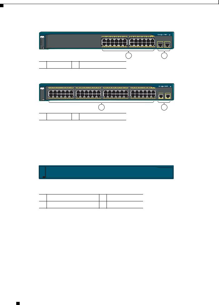
The 10/100 ports on the Catalyst 2960-Plus 24TC-S, 2960-24TC-S, 2960-Plus 48TC-S, and 2960-48TC-S switches are numbered in the same way as the Catalyst 2960-24-S switch. These switches have dual-purpose ports, that is, 10/100/1000 ports 1 and 2 can use either the SFP module or the RJ-45 connector for that port, but not both at the same time. Use the software to set the connector type for these ports. For more information about the dual-purpose port, see the “Dual-Purpose Port” section on
page 1-13. See Figure 1-2 and Figure 1-3.
Figure 1-2
 SYST
SYST
 STAT
STAT
 DUPLX
DUPLX
 SPEED
SPEED
MODE
Catalyst 2960-Plus 24TC-S and 2960-24TC-S Switch Front Panel
Catalyst 2960 |
Series SI |
204631
1 |
2 |
1 10/100 ports 2 Dual-purpose ports
Figure 1-3 Catalyst 2960-Plus 48TC-S and 2960-48TC-S Switch Front Panel
Catalyst 2960
1 |
2 |
3 |
4 |
5 |
6 |
7 |
8 |
9 |
10 |
11 |
12 |
|
13 |
14 |
15 |
16 |
17 |
18 |
19 |
20 |
21 |
22 |
23 |
24 |
|
25 |
26 |
27 |
28 |
29 |
30 |
31 |
32 |
33 |
34 |
35 |
36 |
|
37 |
38 |
39 |
40 |
41 |
42 |
43 |
44 |
45 |
46 |
47 |
48 |
 SYST
SYST
 STAT
STAT
 DUPLX
DUPLX
 SPEED
SPEED
MODE
Series SI
204630
1 |
2 |
1 10/100 ports 2 Dual-purpose ports
Catalyst 2960 Switch Hardware Installation Guide
|
OL-7075-09 |
1-5 |
|
|
|

Chapter 1 Product Overview
Front Panel Description
The 10/100 ports on the Catalyst 2960-48TT-S switch are numbered as follows: The first member of the pair (port 1) is above the second member (port 2), port 3 is above port 4, and so on. This switch has two 10/100/1000 uplink ports, numbered 1 and 2. The See Figure 1-4.
Figure 1-4 Catalyst 2960-48TT-S Switch Front Panel
271431
1 |
2 |
1 10/100 ports 2 10/100/1000 ports
Catalyst 2960-Plus 24PC-L, 2960-24PC-L, 2960-Plus 24PC-S, 2960-24PC-S, 2960-Plus 24LC-L, 2960-Plus 24LC-S, 2960-24LC-S, 2960-Plus 24TC-L, 2960-24TC-L, 2960-Plus 48TC-L, 2960-48TC-L, 2960-24LT-L, 2960-24TT-L, 2960-48TT-L, 2960-Plus 48PST-L, 2960-48PST-L, 2960-Plus 48PST-S, and 2960-48PST-S Switches
The 10/100 ports on the switches are grouped in pairs. The first member of the pair (port 1) is above the second member (port 2), port 3 is above port 4, and so on.
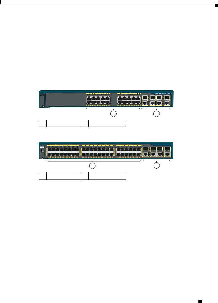
The fixed 10/100 ports on the Catalyst 2960-24PC-L and 2960-24PC-S switches are PoE ports. See Figure 1-5 and Figure 1-6.
Ports 1 to 8 on the Catalyst 2960-24LC-S switch are PoE ports. See Figure 1-7.
Figure 1-5
 SYST
SYST
 RPS
RPS
 STAT
STAT
 DUPLX
DUPLX
 SPEED
SPEED
 PoE
PoE
MODE
Catalyst 2960-Plus 24PC-L and 2960-24PC-L Switch Front Panel
1 |
2 |
3 |
4 |
5 |
6 |
7 |
8 |
9 |
10 |
11 |
12 |
13 |
14 |
15 |
16 |
17 |
18 |
19 |
20 |
21 |
22 |
23 |
24 |
|
|
1X |
|
|
|
|
|
|
|
|
|
|
11X |
13X |
|
|
|
|
|
|
|
|
|
|
23X |
|
204641 |
|
|
|
|
|
|
|
|
|
|
|
|
|
|
|
|
|
|
|
|
|
|
|
1 |
2 |
|
2X |
|
|
|
|
|
|
|
|
|
|
12X |
14X |
|
|
|
|
|
|
|
|
|
|
24X |
|
|
POWER |
|
ETHERNET |
|
|
|
|
|
|
|
|
|
|
|
|
|
|
|
|
|
|
|
|
|
||
1 |
2 |
1 10/100 PoE ports 2 Dual-purpose ports
Figure 1-6 Catalyst 2960-Plus 24PC-S and 2960-24PC-S Switch Front Panel
206731
1 |
2 |
1 10/100 PoE ports 2 Dual-purpose ports
Catalyst 2960 Switch Hardware Installation Guide
1-6 |
OL-7075-09 |
|
|

Chapter 1 Product Overview
Front Panel Description
Figure 1-7 Catalyst 2960-Plus 24LC-L and 2960-24LC-S Switch Front Panel
206730
|
1 |
2 |
3 |
||
|
|
|
|
|
|
1 |
10/100 PoE ports |
3 |
Dual-purpose ports |
|
|
|
|
|
|
|
|
2 |
10/100 ports |
|
|
|
|
|
|
|
|
|
|
The Catalyst 2960-24TC-L and Catalyst 2960-48TC-L switches have dual-purpose ports, that is, 10/100/1000 ports 1 and 2 can use either the SFP module or the RJ-45 connector for that port, but not both. Use the software to set the connector type for these ports. For more information about the dual-purpose port, see the “Dual-Purpose Port” section on page 1-13. See Figure 1-8 and Figure 1-9.
Figure 1-8 Catalyst 2960-Plus 24TC-L and 2960-24TC-L Switch Front Panel
SYST |
|
RPS |
|
STAT |
|
DUPLX |
|
SPEED |
|
MODE |
|
1 |
2 |
1 10/100 ports 2 Dual-purpose ports |
|
204606
Figure 1-9 Catalyst 2960-Plus 48TC-L and 2960-48TC-L Switch Front Panel
 SYST
SYST
 RPS
RPS
 STAT
STAT
 DUPLX
DUPLX
 SPEED
SPEED
MODE 
1 |
2 |
1 10/100 ports 2 Dual-purpose ports
204608
The Catalyst 2960-24LT-L, Catalyst 2960-24TT-L, and Catalyst 2960-48TT-L switches have two 10/100/1000 uplink ports, numbered 1 and 2. Ports 1 to 8 on the Catalyst 2960-24LT-L switch are PoE ports. See Figure 1-10, Figure 1-11, and Figure 1-12.
Figure 1-10 |
Catalyst 2960-24LT-L Switch Front Panel |
|
|
||
|
1 2 |
3 4 5 6 7 8 9 10 11 12 |
13 14 15 16 17 18 19 20 21 22 23 24 |
Catalyst 2960 Series PoE-8 |
|
SYST |
1X |
11X |
13X |
23X |
|
RPS |
|
|
|
|
|
STAT |
|
|
|
|
|
DUPLX |
|
|
|
|
|
SPEED |
|
|
|
1 |
2 |
PoE |
|
|
|
|
|
|
2X |
12X |
14X |
24X |
|
MODE |
POWER |
ETHERNET |
|
|
|
|
|
1 |
2 |
3 |
|
|
|
|
|
|
|
1 |
10/100 PoE ports |
3 |
10/100/1000 uplink ports |
|
|
|
|
|
|
|
|
2 |
10/100 ports |
|
|
|
|
|
|
|
|
|
|
204642
Catalyst 2960 Switch Hardware Installation Guide
|
OL-7075-09 |
1-7 |
|
|
|
Chapter 1 Product Overview
Front Panel Description
Figure 1-11 Catalyst 2960-24TT-L Switch Front Panel
SYST |
|
RPS |
|
STAT |
|
DUPLX |
|
SPEED |
|
MODE |
|
1 |
2 |
1 10/100 ports 2 10/100/1000 uplink ports |
|
Figure 1-12 Catalyst 2960-48TT-L Switch Front Panel
204607
 SYST
SYST
 RPS
RPS
 STAT
STAT
 DUPLX
DUPLX
 SPEED
SPEED
MODE 
1 |
2 |
1 10/100 ports 2 10/100/1000 uplink ports
204609
The Catalyst 2960-48PST-L and 2960-48PST-S switches have two SFP module slots (numbered 1 and 2) and two 10/100/1000 uplink ports (numbered 3 and 4). Ports 1 to 48 on the switch are PoE ports. See Figure 1-13 and Figure 1-14.
Figure 1-13 Catalyst 2960-Plus 48PST-L and 2960-48PST-L Switch Front Panel
3
|
1 |
2 |
3 |
4 |
5 |
6 |
7 |
8 |
9 |
10 |
11 |
12 |
13 |
14 |
15 |
16 |
17 |
18 |
19 |
20 |
21 |
22 |
23 |
24 |
25 |
26 |
27 |
28 |
29 |
30 |
31 |
32 |
33 |
34 |
35 |
36 |
37 |
38 |
39 |
40 |
41 |
42 |
43 |
44 |
45 |
46 |
47 |
48 |
|
SYST 1X |
|
|
|
|
|
|
|
|
|
|
|
11X |
13X |
|
|
|
|
|
|
|
|
|
|
23X |
24X |
|
|
|
|
|
|
|
|
|
|
35X |
37X |
|
|
|
|
|
|
|
|
|
|
47X |
|
RPS |
|
|
|
|
|
|
|
|
|
|
|
|
|
|
|
|
|
|
|
|
|
|
|
|
|
|
|
|
|
|
|
|
|
|
|
|
|
|
|
|
|
|
|
|
|
|
|
1 |
2 |
STAT |
|
|
|
|
|
|
|
|
|
|
|
|
|
|
|
|
|
|
|
|
|
|
|
|
|
|
|
|
|
|
|
|
|
|
|
|
|
|
|
|
|
|
|
|
|
|
|
|
|
DUPLX |
|
|
|
|
|
|
|
|
|
|
|
|
|
|
|
|
|
|
|
|
|
|
|
|
|
|
|
|
|
|
|
|
|
|
|
|
|
|
|
|
|
|
|
|
|
|
|
|
|
SPEED |
|
|
|
|
|
|
|
|
|
|
|
|
|
|
|
|
|
|
|
|
|
|
|
|
|
|
|
|
|
|
|
|
|
|
|
|
|
|
|
|
|
|
|
|
|
|
|
|
|
PoE |
|
|
|
|
|
|
|
|
|
|
|
|
|
|
|
|
|
|
|
|
|
|
|
|
|
|
|
|
|
|
|
|
|
|
|
|
|
|
|
|
|
|
|
|
|
|
|
|
|
|
|
|
|
|
|
|
|
|
|
|
|
|
|
|
|
|
|
|
|
|
|
|
|
|
|
|
|
|
|
|
|
|
|
|
|
|
|
|
|
|
|
|
|
|
|
|
|
3 |
4 |
2X |
|
|
|
|
|
|
|
|
|
|
|
12X |
14X |
|
|
|
|
|
|
|
|
|
|
24X |
26X |
|
|
|
|
|
|
|
|
|
|
36X |
38X |
|
|
|
|
|
|
|
|
|
|
48X |
|
MODE |
POWER |
|
ETHERNET |
|
|
|
|
|
|
|
|
|
|
|
|
|
|
|
|
|
|
|
|
|
|
|
|
|
|
|
|
|
|
|
|
|
|
|
|
|
|
|
|
|
|
|
|
||
|
|
|
|
|
|
|
|
|
|
|
|
|
|
|
|
|
|
|
|
|
|
|
|
1 |
|
|
|
|
|
|
|
|
|
|
|
|
|
|
|
|
|
|
|
|
|
|
|
|
2 |
1 |
10/100 PoE ports |
|
|
|
|
|
|
|
|
|
3 |
|
|
SFP module slots |
|
|
|
|
|
|
|
|
|
||||||||||||||||||||||||||
2 |
10/100/1000 uplink ports |
|
|
|
|
|
|
|
|
|
|
|
|
|
|
|
|
|
|
|
|
|
|
|
|
|
|
|
|
|
|||||||||||||||||||
205644
Figure 1-14 Catalyst 2960-Plus 48PST-S and 2960-48PST-S Switch Front Panel
3
206732
|
1 |
|
2 |
|
|
|
|
|
|
1 |
10/100 PoE ports |
3 |
SFP module slots |
|
|
|
|
|
|
2 |
10/100/1000 uplink ports |
|
|
|
|
|
|
|
|
Catalyst 2960 Switch Hardware Installation Guide
1-8 |
OL-7075-09 |
|
|
Chapter 1 Product Overview
Front Panel Description
Catalyst 2960G-24TC-L and Catalyst 2960G-48TC-L Switches
The 10/100/1000 ports on the Catalyst 2960G-24TC-L and Catalyst 2960G-48TC-L switches are grouped in pairs. The first member of the pair (port 1) is above the second member (port 2), port 3 is above port 4, and so on. The SFP module slots are numbered 21 to 24 on the Catalyst 2960G-24TC-L switch and 45 to 48 on the Catalyst 2960G-48TC-L switch. See Figure 1-15 and Figure 1-16.
The Catalyst 2960G-24TC-L and Catalyst 2960G-48TC-L switches have dual-purpose ports, meaning ports 21 to 24 or 45 to 48 can use either the SFP module or the RJ-45 connector for that port, but not both. Use the software to set the connector type for these ports. For more information about the dual-purpose port, see the “Dual-Purpose Port” section on page 1-13.
Figure 1-15 Catalyst 2960G-24TC-L Switch Front Panel
 SYST
SYST
 RPS
RPS
 STAT
STAT
 DUPLX
DUPLX
 SPEED
SPEED
MODE
1 |
2 |
1 10/100/1000 ports 2 Dual-purpose ports
204610
Figure 1-16 Catalyst 2960G-48TC-L Switch Front Panel
|
1 |
2 |
3 |
4 |
5 |
6 |
7 |
8 |
9 |
10 |
11 |
12 |
13 |
14 |
15 |
16 |
|
17 |
18 |
19 |
20 |
21 |
22 |
23 |
24 |
25 |
26 |
27 |
28 |
29 |
30 |
31 |
32 |
33 |
34 |
35 |
36 |
37 |
38 |
39 |
40 |
41 |
42 |
43 |
44 |
|
Catalyst 2960 SERIES |
|
|
|
|
|
|
||||||||||||||||||||||||||||||||||||||||||||
1X |
|
|
|
|
|
|
|
|
|
|
|
|
|
|
|
|
15X |
17X |
|
|
|
|
|
|
|
|
|
|
|
|
|
|
31X |
33X |
|
|
|
|
|
|
|
|
|
|
42X |
|
|
|
|
|
|
|
|
|
|
|
|
|
|
|
|
|
|
|
|
|
|
|
|
|
|
|
|
|
|
|
|
|
|
|
|
|
|
|
|
|
|
|
|
|
|
|
|
45 |
46 |
47 |
48 |
2X |
|
|
|
|
|
|
|
|
|
|
|
|
12X |
|
|
|
16X |
18X |
|
|
|
|
|
|
|
|
|
|
|
12X |
|
|
32X |
34X |
|
|
|
|
|
|
|
|
|
|
46X |
|
|
|
MODE |
|
|
|
|
|
|
|
|
|
|
|
|
|
|
|
|
|
|
|
|
|
|
|
|
|
|
|
|
|
|
|
|
|
|
|
|
|
|
|
|
|
|
|
|
|
|
|
|
|
|
|
|
|
|
|
|
|
|
|
|
|
|
|
|
|
|
|
|
|
|
1 |
|
|
|
|
|
|
|
|
|
|
|
|
|
|
|
|
|
|
|
|
|
|
|
2 |
|
|
1 |
10/100/1000 ports |
|
2 |
|
|
|
Dual-purpose ports |
|
|
|
|
|
|
|
|
|
|
|
||||||||||||||||||||||||||||||
204611
Catalyst 2960 8-Port Switches
These sections describe the Catalyst 2960 8-port switches:
•Catalyst 2960PD-8TT-L Switch, page 1-9
•Catalyst 2960-8TC-S, Catalyst 2960-8TC-L, and Catalyst 2960G-8TC -L Switches, page 1-10
Catalyst 2960PD-8TT-L Switch
The Catalyst 2960PD-8TT-L (Figure 1-17) switch front panel has a console port, eight 10/100 ports, and a 10/100/1000 uplink port that can receive power from an upstream PoE switch. The switch can also receive power from an optional AC power adapter that is connected through the rear panel.
Catalyst 2960 Switch Hardware Installation Guide
|
OL-7075-09 |
1-9 |
|
|
|

Chapter 1 Product Overview
Front Panel Description
Figure 1-17 Catalyst 2960PD-8TT-L Switch Front Panel
1x |
2x |
3x |
4x |
5x |
6x |
7x |
8x |
CONSOLE |
|
|
|
|
|
|
1 |
SYST |
|
|
|
|
|
|
|
STAT |
|
|
|
|
|
|
|
DPLX |
|
|
|
|
|
|
|
SPD |
|
|
|
|
|
|
|
MODE |
|
|
|
|
|
|
PoE INPUT |
|
1 |
2 |
3 |
|
|
|
|
|
|
1 |
Console port |
3 |
10/100/1000 power input port |
|
|
|
|
|
|
2 |
10/100 ports |
|
|
|
|
|
|
|
|
Catalyst 2960-8TC-S, Catalyst 2960-8TC-L, and Catalyst 2960G-8TC -L Switches
204643
The console ports for the Catalyst 2960-8TC-S, Catalyst 2960-8TC-L, and Catalyst 2960G-8TC-L switches (Figure 1-18 to Figure 1-20) are on the front panels. The switches also have a dual-purpose port that can use either an RJ-45 connector or an SFP module, but not both at the same time. Use the software to set the connector type for these ports.
For more information on the dual-purpose port, see the “Dual-Purpose Port” section on page 1-13. For more information on the console port, see the “Console Port” section on page 1-21.
Figure 1-18 Catalyst 2960-8TC-S Switch Front Panel
|
|
Catalyst 2960 |
SI |
SYST |
|
|
|
STAT |
|
|
|
DPLX |
|
|
|
SPD |
|
|
271432 |
MODE |
|
|
|
1 |
2 |
3 |
|
1 |
Console port |
3 |
Dual-purpose port |
|
|
|
|
2 |
10/100/100 ports |
|
|
|
|
|
|
Figure 1-19 |
|
Catalyst 2960-8TC-L Switch Front Panel |
|
|||||||
|
|
|
|
|
|
|
|
|
Catalyst 2960Series |
|
SYST |
CONSOLE |
1x |
2x |
3x |
4x |
5x |
6x |
7x |
8x |
|
|
|
|
|
|
|
|
|
|
||
STAT |
|
|
|
|
|
|
|
|
|
|
DPLX |
|
|
|
|
|
|
|
|
|
|
SPD |
|
|
|
|
|
|
|
|
|
204627 |
|
|
|
|
|
|
|
|
|
1 |
|
MODE |
|
|
|
|
|
|
|
|
|
|
|
|
|
|
|
|
|
|
|
|
|
|
1 |
|
|
|
|
2 |
|
|
3 |
|
1 |
Console port |
3 |
Dual-purpose port |
|
|
|
|
2 |
10/100/100 ports |
|
|
|
|
|
|
Catalyst 2960 Switch Hardware Installation Guide
1-10 |
OL-7075-09 |
|
|
Chapter 1 Product Overview
Front Panel Description
Figure 1-20 Catalyst 2960G-8TC-L Switch Front Panel
|
|
|
|
|
|
|
|
Catalyst 2960GSeries |
|
SYST |
CONSOLE |
1x |
2x |
3x |
4x |
5x |
6x |
7x |
|
|
|
|
|
|
|
|
|
||
STAT |
|
|
|
|
|
|
|
|
|
DPLX |
|
|
|
|
|
|
|
|
204633 |
SPD |
|
|
|
|
|
|
|
|
|
|
|
|
|
|
|
|
|
1 |
|
|
MODE |
|
|
|
|
|
|
|
|
|
|
|
|
|
|
|
|
|
|
1 |
2 |
3 |
|
|
|
|
|
|
1 |
Console port |
3 |
Dual-purpose port |
|
|
|
|
|
|
2 |
10/100/1000 ports |
|
|
|
|
|
|
|
|
10/100 Ports
You can set the 10/100 ports to operate at 10 or 100 Mb/s in full-duplex or half-duplex mode. You can also set these ports for speed and duplex autonegotiation. The default setting is autonegotiate. When the port is set to autonegotiate, it senses the speed and duplex settings of the attached device and advertises its own capabilities. If the connected device also supports autonegotiation, the switch port negotiates the best connection (that is, the fastest line speed that both devices support and full-duplex transmission if the attached device supports it) and configures itself accordingly. In all cases, the attached device must be within 328 feet (100 meters).
100BASE-TX traffic requires a Category 5 or higher cable. 10BASE-T traffic can use Category 3 or Category 4 cables.
When you connect the switch to workstations, servers, routers, and Cisco IP Phones, be sure that the cable is a straight-through cable. When you connect the switch to switches or hubs, use a crossover cable. Pinouts for the cables are described in Appendix B, “Connector and Cable Specifications.”
You can use the mdix auto interface configuration command in the command-line interface (CLI) to enable the auto-MDIX feature. When the auto-MDIX feature is enabled, the switch detects the required cable type for copper Ethernet connections and configures the interfaces accordingly. Therefore, you can use either a crossover or a straight-through cable for connections to a copper 10/100/1000 or 1000BASE-T SFP module port on the switch, regardless of the type of device on the other end of the connection. For configuration information for this feature, see the switch software configuration guide or the switch command reference.
10/100/1000 Ports
You can set the 10/100/1000 ports to operate at 10, 100, or 1000 Mb/s in full-duplex or half-duplex mode. You can also set these ports for speed and duplex autonegotiation. (The default setting is autonegotiate.) When you set the port for autonegotiation, it senses the speed and duplex settings of the attached device and advertises its own capabilities. If the connected device also supports autonegotiation, the switch port negotiates the best connection (that is, the fastest line speed that both devices support and full-duplex transmission if the attached device supports it) and configures itself accordingly. In all cases, the attached device must be within 328 feet (100 meters).
100BASE-TX and 1000BASE-T traffic requires a Category 5 or higher cable. 10BASE-T traffic can use Category 3 or Category 4 cables.
Catalyst 2960 Switch Hardware Installation Guide
|
OL-7075-09 |
1-11 |
|
|
|

Chapter 1 Product Overview
Front Panel Description
When you connect the switch to workstations, servers, routers, and Cisco IP Phones, be sure that the cable is a straight-through cable. When you connect the switch to switches or hubs, use a crossover cable. When using a straight-through or crossover cable for 1000BASE-T connections, be sure to use a twisted four-pair, Category 5 or higher cable for proper operation. Pinouts for the cables are described in Appendix B, “Connector and Cable Specifications.”
You can use the mdix auto interface configuration command in the CLI to enable the automatic medium-dependent interface crossover (auto-MDIX) feature. When the auto-MDIX feature is enabled, the switch detects the required cable type for copper Ethernet connections and configures the interfaces accordingly. Therefore, you can use either a crossover or a straight-through cable for connections to a copper 10/100/1000 or 1000BASE-T SFP module port on the switch, regardless of the type of device on the other end of the connection. For configuration information for this feature, see the switch software configuration guide or the switch command reference.
PoE Ports (Only Catalyst 2960 PoE Switches)
This section applies only to the Catalyst 2960-24PC-L, 2960-24LT-L, 2960-24PC-S, 2960-24LC-S, 2960 48PST-L, and 2960-48PST-S switches.
Warning Voltages that present a shock hazard may exist on Power over Ethernet (PoE) circuits if interconnections are made using uninsulated exposed metal contacts, conductors, or terminals. Avoid using such interconnection methods, unless the exposed metal parts are located within a restricted access location and users and service people who are authorized within the restricted access location are made aware of the hazard. A restricted access area can be accessed only through the use of a special tool, lock and key or other means of security. Statement 1072
•The 10/100 ports on the Catalyst 2960-Plus 24PC-L, 2960-24PC-L, 2960-Plus 48PST-L, 2960-48PST-L, 2960-Plus 48PST-S, 2960-48PST-S, 2960-Plus 24PC-S, and 2960-24PC-S, switches and ports 1 to 8 of the 10/100 ports on the Catalyst 2960-24LT-L, 2960-Plus 24LC-L, 2960-Plus 24LC-S, and 2960-24LC-S switches provide PoE support for devices that are compliant with IEEE 802.3af. The Cisco prestandard PoE is also supported for Cisco IP Phones and Cisco Aironet Access Points.
•Each of the PoE ports on the Catalyst 2960 switches deliver up to 15.4 W of PoE.
The Catalyst 2960-Plus 24PC-L, 2960-24PC-L, 2960-Plus 48PST-L, 2960-48PST-L, 2960-Plus 48PST-S, 2960-48PST-S, 2960-Plus 24PC-S, and 2960-24PC-S switches deliver a maximum power output of approximately 370-W PoE power.
The Catalyst 2960-24LT-L, 2960-Plus 24LC-L, 2960-Plus 24LC-S, and 2960-24LC-S switches deliver a maximum power output of approximately 124-W PoE power.
•On a per-port basis, you can control whether or not a Catalyst 2960 PoE port automatically provides power when an IP phone or an access point is connected. The device manager, Network Assistant, and the CLI provide PoE settings for each 10/100 PoE port:
–Auto: When you select the Auto setting, the port provides power only if a valid powered device, such as an IEEE 802.3af-compliant powered device, a Cisco prestandard IP phone, or a Cisco prestandard Cisco access point, is connected. The Auto setting is the default.
–Never: When you select the Never setting, the port does not provide power even if a Cisco IP phone or an access point is connected.
Catalyst 2960 Switch Hardware Installation Guide
1-12 |
OL-7075-09 |
|
|

Chapter 1 Product Overview
Front Panel Description
•You also can connect a Cisco IP Phone or Cisco Aironet Access Point to a Catalyst 2960 PoE switch 10/100 port and to an AC power source for redundant power. The powered device might switch to the AC power source as its primary power source upon being connected to it. In that case, the PoE port becomes the backup power source for the powered device.
If the primary source fails, the second power source becomes the primary power source to the powered device. During the power transfer, an IP phone might reboot or reestablish link with the switch.
For information about configuring and monitoring PoE ports, see the switch software
configuration guide. For information about Cisco IP Phones and Cisco Aironet Access Points, see the documentation that came with your IP phone or access point.
Many legacy powered devices, including older Cisco IP phones and access points that do not fully support IEEE 802.3af, might not support PoE when connected to the switches by a crossover cable.
SFP Module Slots
The Catalyst 2960 switches (other than those listed) use Gigabit Ethernet SFP modules for Gigabit uplink connections and 100-Megabit SFP modules for 100-Megabit connections to establish fiber-optic connections. These Catalyst 2960 switches do not have an SFP module slot:
•Catalyst 2960PD-8TT-L
•Catalyst 2960-24LT-L
•Catalyst 2960-24-S
•Catalyst 2960-24TT-L
•Catalyst 2960-48TT-L
•Catalyst 2960-48TT-S
The transceiver modules are field-replaceable, providing the uplink interfaces when you insert an SFP module. You can use the SFP modules for Gigabit uplink connections to other switches. You use fiber-optic cables with LC connectors to connect to a fiber-optic SFP module. You use Category 5 or higher cable with RJ-45 connectors to connect to a copper SFP module.
For more information about these SFP modules, see your SFP module documentation or the release notes for your switch software. For more information about cabling requirements, see Appendix B, “Connector and Cable Specifications.”
Dual-Purpose Port
You can configure a dual-purpose port as either a 10/100/1000 port or as an SFP module port. Each port is considered as a single interface with dual front ends—an RJ-45 connector and an SFP module connector. The dual front ends are not redundant interfaces. The switch activates only one connector of the pair at a time.
By default, the switch dynamically selects the interface type that first links up. However, you can use the media-type interface configuration command to manually select the RJ-45 connector or the
SFP module connector. For information about configuring speed and duplex settings for a dual-purpose uplink, see the software configuration guide.
Each uplink port has two LEDs: one shows the status of the RJ-45 port, and one shows the status of the SFP module port. The port LED is on the active connector.
Catalyst 2960 Switch Hardware Installation Guide
|
OL-7075-09 |
1-13 |
|
|
|
Chapter 1 Product Overview
Front Panel Description
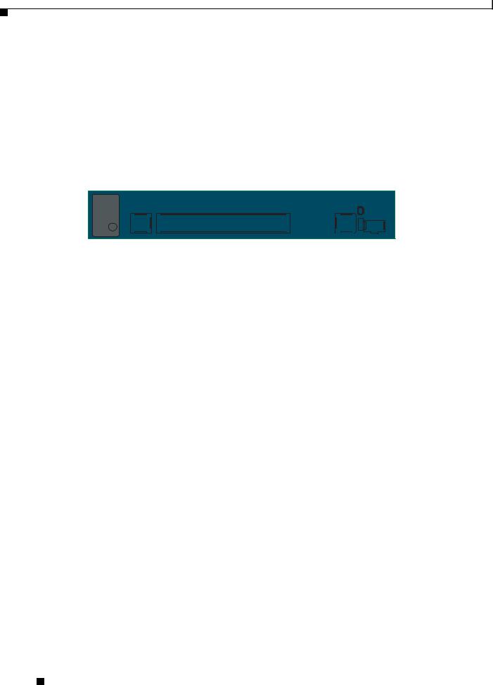
Power Input Port (Catalyst 2960PD-8TT-L Switch)
The Catalyst 2960PD-8TT-L can receive power from these sources:
1.Through a 10/100/1000 port from an upstream Ethernet switch that provides power (complies with IEEE 802.3af). (See Figure 1-21.)
2.Through an external AC power adapter that connects to the back of the switch. This external power adapter (PWR-A=) is not included with the switch, but you can order it from your Cisco representative. (See Figure 1-22.)
Figure 1-21 Connecting Through a 10/100/1000 Port
1x |
2x |
3x |
4x |
5x |
6x |
7x |
8x |
CONSOLE |
|
|
|
|
|
|
1 |
SYST |
|
|
|
|
|
|
|
STAT |
|
|
|
|
|
|
|
DPLX |
|
|
|
|
|
|
|
SPD |
|
|
|
|
|
|
|
MODE |
|
|
|
|
|
|
PoE |
204644
1
Figure 1-22 Connecting Through an External AC Power Adapter
1
48  0.3 A
0.3 A
 270433
1 Power adapter port
LEDs
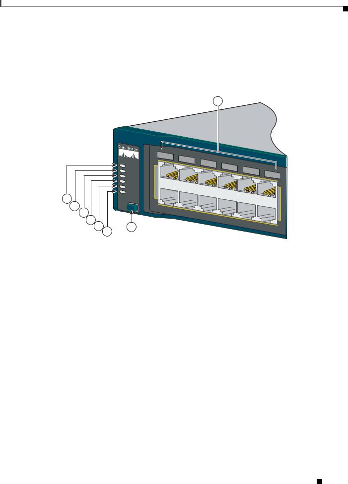
You can use the switch LEDs to monitor switch activity and its performance. Figure 1-23 shows the switch LEDs and the Mode button that you use to select one of the port modes.
All LEDs are visible through the GUI management applications—Network Assistant for multiple switches and the device manager for a single switch. The switch software configuration guide describes how to use the CLI to configure and to monitor individual switches and switch clusters.
Catalyst 2960 Switch Hardware Installation Guide
1-14 |
OL-7075-09 |
|
|
Chapter 1 Product Overview
Front Panel Description
Only the Catalyst 2960 PoE switches have a PoE LED.
The four Catalyst 2960 8-port switches and these models do not have an RPS connector or an RPS LED: Catalyst 2960-24-S, Catalyst 2960-Plus 24TC-S, 2960-24TC-S, 2960-48TT-S, 2960-Plus 48TC-S, 2960-48TC-S.
Figure 1-23 Catalyst 2960 Switch LEDs
8
|
|
1 |
2 |
|
|
|
|
|
|
|
|
|
3 |
4 |
5 |
|
|
|
|
|
1X |
|
|
6 |
|
|
|
||
|
|
|
|
|
|
|
|||
|
SYST |
|
|
|
|
7 |
8 |
|
|
|
RPS |
|
|
|
|
|
9 |
10 |
|
|
STAT |
|
|
|
|
|
|
11 |
12 |
|
|
|
|
|
|
|
|
||
|
|
|
|
|
|
|
|
|
|
|
DUPLX |
|
|
|
|
|
|
|
11X |
|
SPEED |
|
|
|
|
|
|
|
|
|
|
|
|
|
|
|
|
|
|
1 |
PoE |
|
|
|
|
|
|
|
|
|
|
|
|
|
|
|
|
|
|
2 |
MODE |
|
|
|
|
|
|
|
|
3 |
|
|
|
|
|
|
|
|
|
4 |
|
|
|
|
|
|
|
|
|
5 |
7 |
|
|
|
|
|
|
|
204612 |
|
6 |
|
|
|
|
|
|
|
|
|
|
|
|
|
|
|
|
|
1 |
SYST LED |
5 |
Speed LED |
|
|
|
|
2 |
RPS LED |
6 |
PoE LED1 |
3 |
Status LED |
7 |
Mode button |
|
|
|
|
4 |
Duplex LED |
8 |
Port LEDs |
|
|
|
|
1.The PoE LED is only on the Catalyst 2960 PoE switches.
System LED
The System LED shows whether the system is receiving power and is functioning properly. Table 1-2 lists the LED colors and their meanings.
Table 1-2 |
System LED |
|
|
Color |
System Status |
|
|
Off |
System is not powered on. |
|
|
Green |
System is operating normally. |
|
|
Amber |
System is receiving power but is not functioning properly. |
|
|
Catalyst 2960 Switch Hardware Installation Guide
|
OL-7075-09 |
1-15 |
|
|
|

Chapter 1 Product Overview
Front Panel Description
RPS LED
The RPS LED shows the RPS status. Table 1-3 lists the LED colors and their meanings.
Note The Catalyst 2960 8-port switches, and the Catalyst 2960-24-S, 2960-Plus 24TC-S, 2960-24TC-S, 2960-Plus 48TC-S, 2960-48TC-S, and 2960-48TT-S switches do not have an RPS LED.
Table 1-3 |
RPS LED |
|
|
|
|
Color |
|
RPS Status |
|
|
|
Off |
|
RPS is off or not properly connected. |
|
|
|
Green |
|
RPS is connected and ready to provide back-up power, if required. |
|
|
|
Blinking green |
|
RPS is connected but is unavailable because it is providing power to another device |
|
|
(redundancy has been allocated to a neighboring device). |
|
|
|
Amber |
|
The RPS is in standby mode or in a fault condition. Press the Standby/Active button |
|
|
on the RPS, and the LED should turn green. If it does not, the RPS fan could have |
|
|
failed. Contact Cisco Systems. |
|
|
|
Blinking amber |
|
The internal power supply in a switch has failed, and the RPS is providing power |
|
|
to the switch (redundancy has been allocated to this device). |
|
|
|
For more information about the Cisco RPS 2300 or the Cisco RPS 675, see the related hardware |
||
installation guide for that power system. |
||
Port LEDs and Modes
The port LEDs, as a group or individually, display information about the switch and about the individual ports (Table 1-4):
Table 1-4 |
Modes for Port LEDs |
|
|
|
|
|
|
Selected Mode |
|
|
|
LED |
|
Port Mode |
Description |
|
|
|
|
STAT |
|
Port status |
The port status. This is the default mode. |
|
|
|
|
DUPLX |
|
Port duplex mode |
The port duplex mode: full duplex or half duplex. |
|
|
|
|
SPEED1 |
|
Port speed |
The port operating speed: 10, 100, or 1000 Mb/s. |
PoE2 |
|
PoE port power |
The PoE status. |
1.When installed in Catalyst 2960 switches, 1000BASE-T SFP modules can operate at 10, 100, or 1000 Mb/s in full-duplex mode or at 10 or 100 Mb/s in half-duplex mode.
2.The PoE LED is only on the Catalyst 2960 PoE switches.
Catalyst 2960 Switch Hardware Installation Guide
1-16 |
OL-7075-09 |
|
|

Chapter 1 Product Overview
Front Panel Description
Even if the PoE mode is not selected, the PoE LED shows PoE problems when they are detected (Table 1-5). The PoE LED applies only to Catalyst 2960 switches that support PoE.
|
|
Table 1-5 |
|
PoE Mode LED |
|
|
|
|
|
|
|
|
|
|
|
Color |
|
|
PoE Status |
|
|
|
|
|
|
|
|
|
|
Off |
|
|
PoE mode is not selected. None of the 10/100 PoE ports have been denied power |
|
|
|
|
|
|
or are in a fault condition. |
|
|
|
|
|
|
|
|
|
|
Green |
|
|
PoE mode is selected, and the PoE status is shown on the port LEDs. |
|
|
|
|
|
|
|
|
|
|
Blinking amber |
|
PoE mode is not selected. At least one of the 10/100 PoE ports has been denied |
|
|
|
|
|
|
|
power, or at least one of the ports has a PoE fault. |
|
|
|
|
|
|
|
|
|
|
To select or change a mode, press the Mode button until the desired mode is highlighted. When you |
|
|||
|
|
change port modes, the meanings of the port LED colors also change. Table 1-6 explains how to interpret |
|
|||
|
|
the port LED colors in different port modes. |
|
|||
Table 1-6 |
Meaning of Port LED Colors in Different Modes on the Switch |
|
||||
|
|
|
|
|||
Port Mode |
LED Color |
Meaning |
|
|||
|
|
|
|
|||
STAT |
Off |
No link, or port was administratively shut down. |
|
|||
(port status) |
|
|
|
|
|
|
Green |
Link present. |
|
||||
|
|
|||||
|
|
|
|
|||
|
Blinking green |
Activity. Port is sending or receiving data. |
|
|||
|
|
|
|
|||
|
Alternating |
Link fault. Error frames can affect connectivity, and errors such as excessive collisions, |
|
|||
|
green-amber |
cyclic redundancy check (CRC) errors, and alignment and jabber errors are monitored for a |
|
|||
|
|
|
link-fault indication. |
|
||
|
|
|
|
|||
|
Amber |
Port is blocked by Spanning Tree Protocol (STP) and is not forwarding data. |
|
|||
|
|
|
Note After a port is reconfigured, the port LED can remain amber for up to 30 seconds as |
|
||
|
|
|
|
|
STP checks the network topology for possible loops. |
|
|
|
|
|
|||
|
Blinking amber |
Port is blocked by STP and is not sending or receiving packets. |
|
|||
|
|
|
|
|||
DUPLX |
Off |
Port is operating in half duplex. |
|
|||
(duplex) |
|
|
|
|
|
|
Green |
Port is operating in full duplex. |
|
||||
|
|
|||||
|
|
|
|
|||
SPEED |
10/100 and 10/100/1000 ports |
|
||||
|
|
|
|
|||
|
Off |
Port is operating at 10 Mb/s. |
|
|||
|
|
|
|
|||
|
Green |
Port is operating at 100 Mb/s. |
|
|||
|
|
|
|
|||
|
Blinking green |
Port is operating at 1000 Mb/s. |
|
|||
|
|
|
|
|
|
|
|
SFP ports |
|
|
|
|
|
|
|
|
|
|||
|
Off |
Port is operating at 10 Mb/s. |
|
|||
|
|
|
|
|||
|
Green |
Port is operating at 100 Mb/s. |
|
|||
|
|
|
|
|||
|
Blinking green |
Port is operating at 1000 Mb/s. |
|
|||
|
|
|
Note When installed in Catalyst 2960 switches, 1000BASE-T SFP modules can operate at |
|
||
|
|
|
|
|
10, 100, or 1000 Mb/s in full-duplex mode or at 10 or 100 Mb/s in half-duplex mode. |
|
|
|
|
|
|
|
|
Catalyst 2960 Switch Hardware Installation Guide
|
OL-7075-09 |
1-17 |
|
|
|
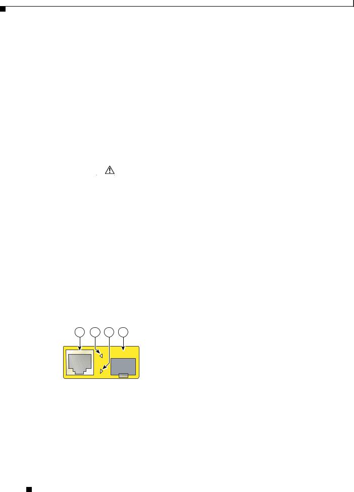
Chapter 1 Product Overview
Front Panel Description
Table 1-6 |
Meaning of Port LED Colors in Different Modes on the Switch (continued) |
|
||||
|
|
|
|
|||
Port Mode |
LED Color |
Meaning |
|
|||
|
|
|
|
|||
PoE |
Off |
PoE is off. |
|
|||
|
|
|
If the powered device is receiving power from an AC power source, the PoE port LED is off |
|
||
|
|
|
even if the powered device is connected to the switch port. |
|
||
|
|
|
|
|
||
|
Green |
|
PoE is on. The port LED is green only when the switch port is providing power. |
|
||
|
|
|
|
|
||
|
Alternating green |
|
PoE is denied because providing power to the powered device will exceed the switch power |
|
||
|
and amber |
|
capacity. The Catalyst 2960-Plus 24PC-L, 2960-24PC-L, 2960-Plus 48PST-L, |
|
||
|
|
|
2960-48PST-L, 2960-Plus 48PST-S, 2960-48PST-S, 2960-Plus 24PC-S, and 2960-24PC-S |
|
||
|
|
|
switches provide up to 370 W of power. The Catalyst 2960-24LT-L, 2960-Plus 24LC-L, |
|
||
|
|
|
2960-Plus 24LC-S, and 2960-24LC-S switches provide up to 124 W of power. |
|
||
|
|
|
|
|||
|
Blinking amber |
PoE is off due to a fault. |
|
|||
|
|
|
|
|
|
|
|
|
|
Caution PoE faults are caused when noncompliant cabling or powered devices are |
|
||
|
|
|
|
|
connected to a PoE port. Only standard-compliant cabling can be used to connect |
|
|
|
|
|
|
Cisco prestandard IP Phones or wireless access points or IEEE 802.3af-compliant |
|
|
|
|
|
|
devices to PoE ports. You must remove from the network the cable or device that |
|
|
|
|
|
|
causes a PoE fault. |
|
|
|
|
|
|
|
|
|
|
|
|
|
||
|
Amber |
|
PoE for the port has been disabled. By default, PoE is enabled. |
|
||
|
|
|
|
|
|
|
Dual-Purpose Port LEDs
The LEDs on a dual-purpose port show whether an RJ-45 connector is connected to the port, or if an SFP module is installed in the slot. See the example in Figure 1-24. You can configure each port as either a 10/100/1000 port through the RJ-45 connector or as an SFP module, but not both at the same time. The LEDs show how the port is being used (Ethernet or SFP module).
The LED colors have the same meanings as described in Table 1-4 and Table 1-6.
Figure 1-24 Dual-Purpose Port LEDs
1 2 3 4
1 |
RJ-45 connector |
3 |
SFP module port in-use LED |
|
|
|
|
2 |
RJ-45 port in-use LED |
4 |
SFP module slot |
|
|
|
|
Catalyst 2960 Switch Hardware Installation Guide
1-18 |
OL-7075-09 |
|
|
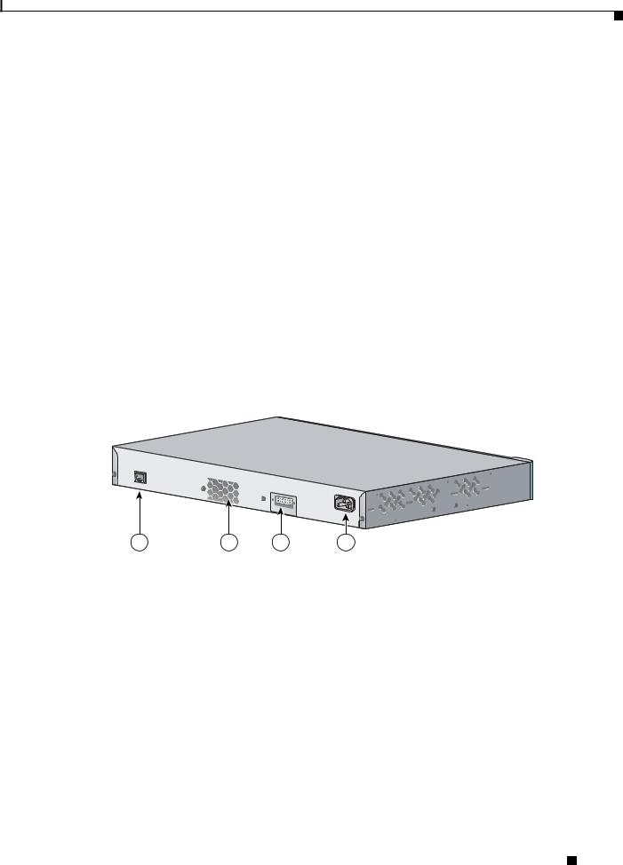
Chapter 1 Product Overview
Rear Panel Description
Cable Guard for the Catalyst 2960 8-Port Switches
You can order an optional cable guard to secure cables to the front of the Catalyst 2960-8TC-L, 2960G-8TC-L, 2960-8TC-S, and 2960PD-8TT-L switches and prevent them from being accidentally removed.
To order a cable guard, contact your Cisco representative using these part numbers:
•CBLGRD-C2960-8TC: Catalyst 2960-8TC-L, 2960-8TC-S, and 2960PD-8TT-L switches
•CBLGRD-C2960G-8TC: Cisco Catalyst 2960G-8TC switch
Rear Panel Description
•Internal Power Supply, page 1-20
•Cisco RPS, page 1-20
•Console Port, page 1-21
Depending on the Catalyst 2960 switch model, the switch can have an RJ-45 console port, a fan exhaust, an RPS connector, and an AC power connector (see Figure 1-25 for an example of a Catalyst 2960 rear panel).
Figure 1-25 Catalyst 2960 Switch Rear Panel
CONSOLE
1 |
2 |
3 |
4 |
137071 |
1 |
RJ-45 console port1 |
3 |
RPS connector 2 |
2 |
Fan exhaust3 |
4 |
AC power connector4 |
1.The Catalyst 2960 8-port switches have the console port on the front panel rather than on the rear panel.
2.These Catalyst 2960 switches do not have an RPS connector: Catalyst 8-port switches, 2960-24-S, 2960-Plus 24TC-S, 2960-24TC-S, 2960-Plus 48TC-S, 2960-48TC-S, and 2960-48TT-S switches.
3.The Catalyst 2960 8-port switches do not have a fan.
4.The Catalyst 2960PD-8TT-L switch does not have an AC internal power supply.
Catalyst 2960 Switch Hardware Installation Guide
|
OL-7075-09 |
1-19 |
|
|
|

Chapter 1 Product Overview
Rear Panel Description
Internal Power Supply
All switches other than the Catalyst 2960PD-8TT-L are powered through their internal power supply. The internal power supply is an autoranging unit that supports input voltages between 100 and 240 VAC. Use the supplied AC power cord to connect the AC power connector to an AC power outlet.
Note The Catalyst 2960PD-8TT-L switch does not have a internal power supply. For more information, see “Power Input Port (Catalyst 2960PD-8TT-L Switch)” section on page 1-14.
Cisco RPS
Depending on the switch model, you can connect the switch to either of these Cisco redundant power systems (RPS) to provide backup power if the switch power supply fails:
•“Cisco RPS 2300” section on page 1-20
•“Cisco RPS 675” section on page 1-21
Connect the switch and the Cisco RPS to the same AC power source. Use the RPS connector cable supplied with the RPS to connect the RPS to the switch.
Warning Attach only the following Cisco RPS model to the RPS receptacle: PWR-RPS2300 / PWR675-AC-RPS-N1 Statement 370
Note These Catalyst 2960 switches do not have an RPS connector: Catalyst 8-port switches, 2960-24-S, 2960-Plus 24TC-S, 2960-24TC-S, 2960-Plus 48TC-S, 2960-48TC-S, 2960-48TT-S, 2960-Plus 48PST-S, 2960-48PST-S, 2960-Plus 24PC-S, 2960-24PC-S, 2960-Plus 24LC-S, and 2960-24LC-S switches.
Note These Catalyst 2960 switches support only the Cisco RPS 2300: Catalyst 2960-24PC-L, 2960-24LT-L, and 2960-48PST-L switches.
For complete information about the Cisco RPS products, including compatibility matrixes listing the supported RPS for each Catalyst 2960 switch, see the RPS documents on Cisco.com:
http://www.cisco.com/en/US/products/ps7148/prod_installation_guides_list.html
Cisco RPS 2300
The Cisco RPS 2300 is a redundant power system that supports six network switches and provides power to one or two failed switches at a time. It automatically senses when the internal power supply of a connected switch fails and provides power to the failed switch, preventing loss of network traffic.
The Cisco RPS 2300 has two output levels: -52 V and 12 V. The total maximum output power depends on the installed power-supply modules.
All supported, connected switches can simultaneously communicate with the RPS 2300. You can configure these RPS 2300 features through the switch software:
• Enable RPS active or standby mode for each connected switch
Catalyst 2960 Switch Hardware Installation Guide
1-20 |
OL-7075-09 |
|
|
Loading...