


 Loading...
Cisco C1101-4P, C1111-8P, C1111-4P, C1112-8P, C1113-8PM Service Manual
...Hardware Installation Guide for the Cisco 1100 Series Integrated Services Router
Last Modified: 2018-04-04
Americas Headquarters
Cisco Systems, Inc. 170 West Tasman Drive
San Jose, CA 95134-1706 USA http://www.cisco.com Tel: 408 526-4000
800 553-NETS (6387) Fax: 408 527-0883
© 2017-2017 Cisco Systems, Inc. All rights reserved.

C O N T E N T S
P r e f a c e
C H A P T E R 1
C H A P T E R 2
Preface vii
Audience vii
Document Organization vii
Document Conventions viii
Related Documentation ix
Obtaining Documentation and Submitting a Service Request x
Overview of Cisco 1000 Series Integrated Services Routers 1
Overview 1
About Cisco 1100 Series Integrated Service Routers 1
Chassis Views 2
Labels on the Router 3
For Additional Help Locating Labels on the Router 4
Hardware Features 4
Interface Ports 4
Power-over-Ethernet (PoE) 5
LED Indicators 5
Reset Button 10
Slots and Interfaces 10
About Slots, Subslots, and Port Numbering 10
Subslot/Bay Numbering 11
Specification 11
Periodic Inspection and Cleaning 14
Preparing for Router Installation 15
Preparing for Router Installation 15
Safety Recommendations 15
Hardware Installation Guide for the Cisco 1100 Series Integrated Services Router
iii

Contents
C H A P T E R 3
Safety With Electricity 15
Preventing Electrostatic Discharge Damage 16
General Site Requirements 16
Site Selection Guidelines 17
Rack Requirements 17
Router Environmental Requirements 17
Power Guidelines and Requirements 18
Network Cabling Specifications 18
Console Port Connections 19
EIA/TIA-232 19
USB Serial Console 19
Console Port Considerations 20
Preparing for Network Connections 20
Ethernet Connections 20
Required Tools and Equipment for Installation and Maintenance 20
Installation Checklist 21
Creating a Site Log 22
Installing and Connecting the Router 23
Installing and Connecting the Router 23
Safety Warnings 23
What You Need to Know 23
Before You Begin 24
Unpacking the Router 24
Installing the Router 24
Installing a Cisco 1100 Series ISR 24
Attaching the Chassis 25
Mounting on the Wall 25
Attaching DIN Rail Brackets 28
Mounting the Router in a Rack 30
Setting the Chassis on a Desktop 31
Chassis Grounding 31
Connecting to a Console Terminal or Modem 32
Connecting to the Serial Port with Microsoft Windows 33
Connecting to the Console Port with Mac OS X 34
Hardware Installation Guide for the Cisco 1100 Series Integrated Services Router
iv

Contents
C H A P T E R 4
C H A P T E R 5
Connecting to the Console Port with Linux |
34 |
|
|
|
|
|||
Installing the Cisco Microsoft Windows USB Device Driver |
35 |
|
|
|||||
Installing the Cisco Microsoft Windows XP USB Driver |
35 |
|
||||||
Installing the Cisco Microsoft Windows 2000 USB Driver |
36 |
|
||||||
Installing the Cisco Microsoft Windows Vista USB Driver |
36 |
|
||||||
Installing the Cisco Microsoft Windows 8/Windows 10 USB Driver |
36 |
|||||||
Uninstalling the Cisco Microsoft Windows USB Driver |
37 |
|
|
|
||||
Uninstalling the Cisco Microsoft Windows XP and 2000 USB Driver |
37 |
|||||||
Uninstalling the Cisco Microsoft Windows Vista USB Driver 38 |
|
|||||||
Connecting WAN and LAN Interfaces 38 |
|
|
|
|
|
|
|
|
Ports and Cabling 39 |
|
|
|
|
|
|
|
|
Connection Procedures and Precautions |
39 |
|
|
|
|
|
||
ROM Monitor Overview and Basic Procedures 41 |
|
|
|
|
|
|
||
ROM Monitor Overview and Basic Procedures |
41 |
|
|
|
|
|
||
ROM Monitor Overview 41 |
|
|
|
|
|
|
|
|
Entering ROM Monitor Mode 42 |
|
|
|
|
|
|
|
|
Checking the Current ROMmon Version |
42 |
|
|
|
|
|||
Commonly Used ROM Monitor Commands 43 |
|
|
|
|
||||
Displaying the Available ROM Monitor Commands |
43 |
|
|
|
||||
Examples 44 |
|
|
|
|
|
|
|
|
Changing the ROM Monitor Prompt 44 |
|
|
|
|
|
|
||
Displaying the Configuration Register Setting 44 |
|
|
|
|
||||
Environment Variable Settings 45 |
|
|
|
|
|
|
|
|
Frequently Used Environmental Variables |
45 |
|
|
|
|
|||
Displaying Environment Variable Settings |
45 |
|
|
|
|
|||
Entering Environment Variable Settings |
46 |
|
|
|
|
|
||
Saving Environment Variable Settings |
46 |
|
|
|
|
|
||
Exiting ROM Monitor Mode |
46 |
|
|
|
|
|
|
|
Configuration Example |
47 |
|
|
|
|
|
|
|
Upgrading the ROMmon for a Router |
47 |
|
|
|
|
|
||
Installing and Upgrading Internal Modules and FRUs 49
Installing and Upgrading Internal Modules and FRUs 49
Safety Warnings 49
Hardware Installation Guide for the Cisco 1100 Series Integrated Services Router
v

Contents
C H A P T E R 6
Accessing Internal Modules 49
Replacing the Chassis Cover 50
Removing the Cover 50
Replacing the Cover 51
Locating Internal and External Slots for Modules 51
Installing the Internal PoE Daughter Card 52
Removing and Replacing the Internal PoE Daughter Card 53
Removing and Replacing the USB Flash Token Memory Stick 53
AC Power Supplies 54
Overview of the AC Power Supply 54
Installing and Removing SFP Modules 54
Installing SFPs 61
Removing SFP Modules 61
Declaration of Conformity for RF Exposure 63
Declaration of Conformity of RF Exposure 63
Hardware Installation Guide for the Cisco 1100 Series Integrated Services Router
vi

Preface
• Audience, page vii
• Document Organization, page vii
• Document Conventions, page viii
• Related Documentation, page ix
• Obtaining Documentation and Submitting a Service Request, page x
Audience
This guide is intended for Cisco equipment providers and service personnel who are technically knowledgeable and familiar with Cisco routers and Cisco IOS software and features. They would understand how to install, configure, and maintain the router, and they should be familiar with electronic circuitry and wiring practices, and have experience as an electronic or electromechanical technician. This guide identifies certain procedures that should be performed only by trained and qualified personnel.
Document Organization
This guide includes the following chapters and appendix::
Chapter//Appendix |
Title |
Description |
Chapter 1 |
Overview of the Cisco |
Describes the router chassis views, general hardware |
|
1100 Series ISR |
features, slot, port and interface information, and LED |
|
|
indicators. |
Chapter 2 |
Preparing for Router |
Describes site requirements and the equipment needed |
|
Installation |
to install the router. |
Chapter 3 |
Installing and |
Describes how to install and connect the router to LAN |
|
Connecting the Router |
and WAN. |
Hardware Installation Guide for the Cisco 1100 Series Integrated Services Router
vii

Preface
Document Conventions
Chapter//Appendix |
Title |
Description |
Chapter 4 |
ROM Monitor Overview |
|
and Basic Procedures |
Chapter 5 |
InstallingandUpgrading |
|
Internal Modules and |
|
FRUs |
Provides an overview of ROM Monitor concepts and operations.
Describes how to install and upgrade internal modules and field replaceable units1 on the router.
1 Field Replaceable Unit
Document Conventions
This document uses the following conventions:
Convention |
Description |
^ or Ctrl |
Both the ^ symbol and Ctrl represent the Control (Ctrl) key on a keyboard. |
|
For example, the key combination ^D or Ctrl-D means that you hold |
|
down the Control key while you press the D key. (Keys are indicated in |
|
capital letters but are not case sensitive.) |
bold font |
Commands and keywords and user-entered text appear in bold font. |
Italic font |
Document titles, new or emphasized terms, and arguments for which you |
|
supply values are in italic font. |
Courier font |
Terminal sessions and information the system displays appear in courier |
|
font. |
Bold Courier font |
Bold Courier font indicates text that the user must enter. |
[x] |
Elements in square brackets are optional. |
... |
An ellipsis (three consecutive nonbolded periods without spaces) after |
|
a syntax element indicates that the element can be repeated. |
| |
A vertical line, called a pipe, indicates a choice within a set of keywords |
|
or arguments. |
[x | y] |
Optional alternative keywords are grouped in brackets and separated by |
|
vertical bars. |
{x | y} |
Required alternative keywords are grouped in braces and separated by |
|
vertical bars. |
Hardware Installation Guide for the Cisco 1100 Series Integrated Services Router
viii

Preface
Related Documentation
Convention |
Description |
[x {y | z}] |
Nested set of square brackets or braces indicate optional or required |
|
choices within optional or required elements. Braces and a vertical bar |
|
within square brackets indicate a required choice within an optional |
|
element. |
string |
A nonquoted set of characters. Do not use quotation marks around the |
|
string or the string will include the quotation marks. |
< > |
Nonprinting characters such as passwords are in angle brackets. |
[ ] |
Default responses to system prompts are in square brackets. |
!, # |
An exclamation point (!) or a pound sign (#) at the beginning of a line |
|
of code indicates a comment line. |
Reader Alert Conventions
This document uses the following conventions for reader alerts:
Note Means reader take note. Notes contain helpful suggestions or references to material not covered in the manual.
Tip Means the following information will help you solve a problem.
Caution Means reader be careful. In this situation, you might do something that could result in equipment damage or loss of data.
Timesaver Means the described action saves time. You can save time by performing the action described in the paragraph.
Warning Means reader be warned. In this situation, you might perform an action that could result in bodily injury.
Related Documentation
For related release documentation, see the following URLs:
Hardware Installation Guide for the Cisco 1100 Series Integrated Services Router
ix

Preface
Obtaining Documentation and Submitting a Service Request
Cisco 1100 Series ISR Release Notes: https://www.cisco.com/c/en/us/td/docs/routers/access/1100/release/ 16-6-2/isr1k-rel-notes-xe-16-6.html
Cisco 1100 Series ISR Configuration Guide - https://www.cisco.com/c/en/us/td/docs/routers/access/1100/ software/configuration/guide/cisco_1100_series_swcfg.html
Obtaining Documentation and Submitting a Service Request
For information on obtaining documentation, submitting a service request, and gathering additional information, see What’s New in Cisco Product Documentation at: http://www.cisco.com/en/US/docs/general/whatsnew/ whatsnew.html.
Subscribe to What’s New in Cisco Product Documentation, which lists all new and revised Cisco technical documentation, as an RSS feed and deliver content directly to your desktop using a reader application. The RSS feeds are a free service.
Hardware Installation Guide for the Cisco 1100 Series Integrated Services Router
x
C H A P T E R 1
Overview of Cisco 1000 Series Integrated
Services Routers
• Overview , page 1
Overview
Cisco 1000 Series Integrated Services Routers (ISRs) with Cisco IOS XE Software combine Internet access, comprehensive security, and wireless services (LTE Advanced 3.0, Wireless WAN and Wireless LAN), are high-performance devices that are easy to deploy and manage. The routers are well suited for deployment as customer premises equipment (CPE) in enterprise branch offices, and in service provider managed service environments.
The Cisco 1000 ISRs provide enterprise grade-wired line-like functionality, such as quality of service (QoS) for cellular, Multi-VRF, advanced VPN, and unified communications solutions over LTE.
The 1000 Series also provides the ability to extend Cisco product-based networks to remote offices with a relatively low incremental investment, as well as to enable managed services offerings based on end-to-end Cisco system architecture.
About Cisco 1100 Series Integrated Service Routers
The Cisco 1100 Series ISRs are fixed branch routers based on the Cisco IOS XE Everest 16.6.2 operating system, with a multi-core Data Plane.
The two types of platforms supported on Cisco 1100 Series ISRs are 8-port and 4-port platforms.
8-port platforms are high-performance, managed service provider and enterprise platforms having:
•8-port integrated front panel switch ports
•Optional PoE on LAN daughter card with support up to 4PoE/2PoE+ports
•Optional WLAN support - 802.11ac WAVE 2
•4G LTE-Advanced support with carrier aggregation
Hardware Installation Guide for the Cisco 1100 Series Integrated Services Router
1

Overview of Cisco 1000 Series Integrated Services Routers
Chassis Views
4-port platforms are midrange performance, managed service provider platforms and enterprise platforms having:
•4-port integrated front panel switch ports
•VDSL2 and ADSL2/2+ support
•Optional POE on LAN daughter card supporting 2PoE/1PoE+ ports
•Optional WLAN support - 802.11ac WAVE 2
•4G LTE-Advanced support with carrier aggregation
Chassis Views
This section contains views of the front and back panels of the Cisco 1100 Series ISR, showing locations of the power and signal interfaces, interface slots, status indicators, and chassis identification labels.
Bezel View
Figure 1: Cisco 1100 Series ISR - Bezel View
1 |
Status |
2 |
VPN |
3 |
WiFi |
4 |
GPS |
5 |
LTE Signal Intensity |
6 |
LTE Data/SIM |
7 |
Illuminated Cisco Logo |
|
|
Hardware Installation Guide for the Cisco 1100 Series Integrated Services Router
2

Overview of Cisco 1000 Series Integrated Services Routers
Labels on the Router
I/O View
Figure 2: Cisco 1100 Series ISR - I/O Views
1 |
LTE Antennas – Main |
2 |
LAN |
|
and Diversity |
|
|
3 |
GPS Connection |
4 |
CLEI Label |
5 |
Serial Number |
6 |
Grounding |
7 |
Reset Button |
8 |
Power Switch |
9 |
4-pin Power Connector |
10 |
GE 0/0/1 |
11 |
GE 0/0/0 - RJ45 |
12 |
GE 0/0/0 - SFP |
13 |
USB3.0 |
14 |
uSIM*2 |
15 |
LTE Provisioning Port |
16 |
RJ45 / Micro USB |
|
|
|
Console |
17 |
DSL |
18 |
Kensington Lock Slot |
Labels on the Router
To obtain a software license, you need a product authorization key (PAK) and the unique device identifier (UDI) of the device where the license will be installed.
Hardware Installation Guide for the Cisco 1100 Series Integrated Services Router
3
Overview of Cisco 1000 Series Integrated Services Routers
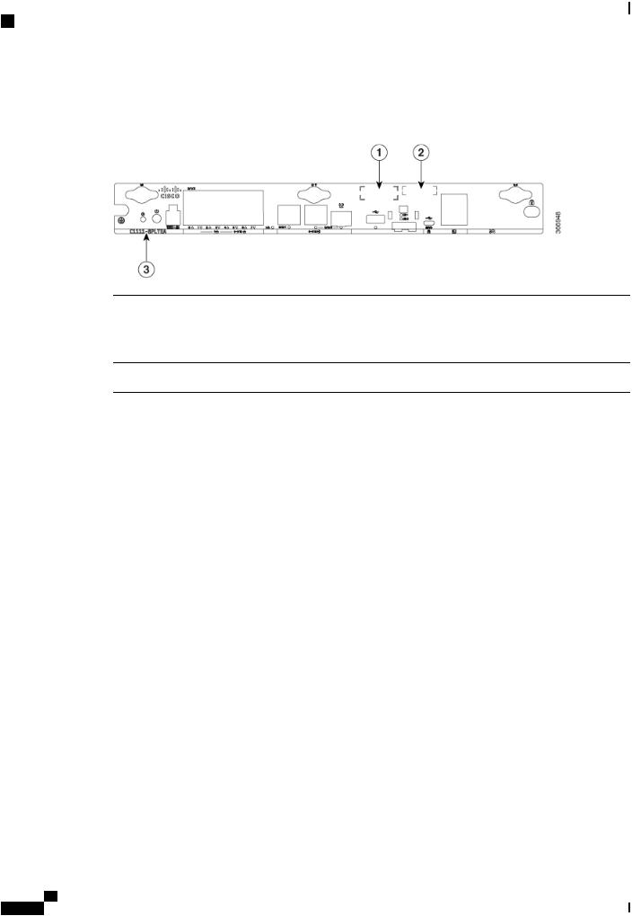
For Additional Help Locating Labels on the Router
Figure shows the location of the labels on the Cisco 1100 Series ISRs:
Figure 3: Labels on the Routers
Sl. No |
Name |
Description |
1 |
CLEI Number |
Common Language Equipment |
|
|
Identifier (CLEI) number |
2 |
Serial Number |
|
3 |
PID Family Name |
Product Identification Number |
For Additional Help Locating Labels on the Router
Use the Cisco Product Identification (CPI) tool to find labels on the router. The tool provides detailed illustrations and descriptions of where the labels are located on Cisco products. It includes the following features:
•A search option that allows browsing for models by using a tree-structured product hierarchy
•A search field on the final results page that makes it easier to look up multiple products
•End-of-sale products clearly identified in results lists
The tool streamlines the process of locating serial number labels and identifying products. Serial number information expedites the entitlement process and is important for access to support services.
Hardware Features
This section describes the hardware features in the routers.
Interface Ports
The Cisco ISR C1100-8P series comes with 8-Gigabit Ethernet LAN ports, and two WAN ports, with options for one LTE modem and one WLAN interface.
Hardware Installation Guide for the Cisco 1100 Series Integrated Services Router
4

Overview of Cisco 1000 Series Integrated Services Routers
Hardware Features
The Cisco ISR C1100-4P series comes with 4-Gigabit Ethernet LAN ports, and two WAN ports, with options for one LTE modem and one WLAN interface.
Power-over-Ethernet (PoE)
The C1100-8P series has 8 Ethernet LAN ports. Four of the Ethernet LAN ports are PoE-capable, LAN ports 0-3. A total of 80W of PoE power is available across the four PoE-capable ports on the C1100-8P series.
The C1100-4P series has 4 Ethernet LAN ports. Two of the Ethernet LAN ports are PoE-capable, LAN ports 0-1. A total of 60W of PoE power is available across the two PoE-capable ports on the C1100-4P series.
Each individual PoE-capable Ethernet LAN port is capable of PoE 802.3af or PoE+ 802.3at functionality. The total number of PoE and/or PoE+ devices that can be enabled on the PoE ports at any one time is a function of the PoE power available from the external power supply. Software will allocate PoE power based on the PoE power requested by the device on each port; and manage the total available power so as not to allocate more power than what is available.
LED Indicators
The following figures and table summarizes the LED indicators that are located in the router bezel or chassis, but not on the interface cards and modules.
Figure 4: LED Indicators - Bezel Side
1 |
Status |
2 |
VPN |
3 |
WLAN |
4 |
GPS |
5 |
LTE RSSI/Mode |
6 |
LTE DATA/SIM |
7 |
Cisco Logo |
|
|
Hardware Installation Guide for the Cisco 1100 Series Integrated Services Router
5
Overview of Cisco 1000 Series Integrated Services Routers
Hardware Features
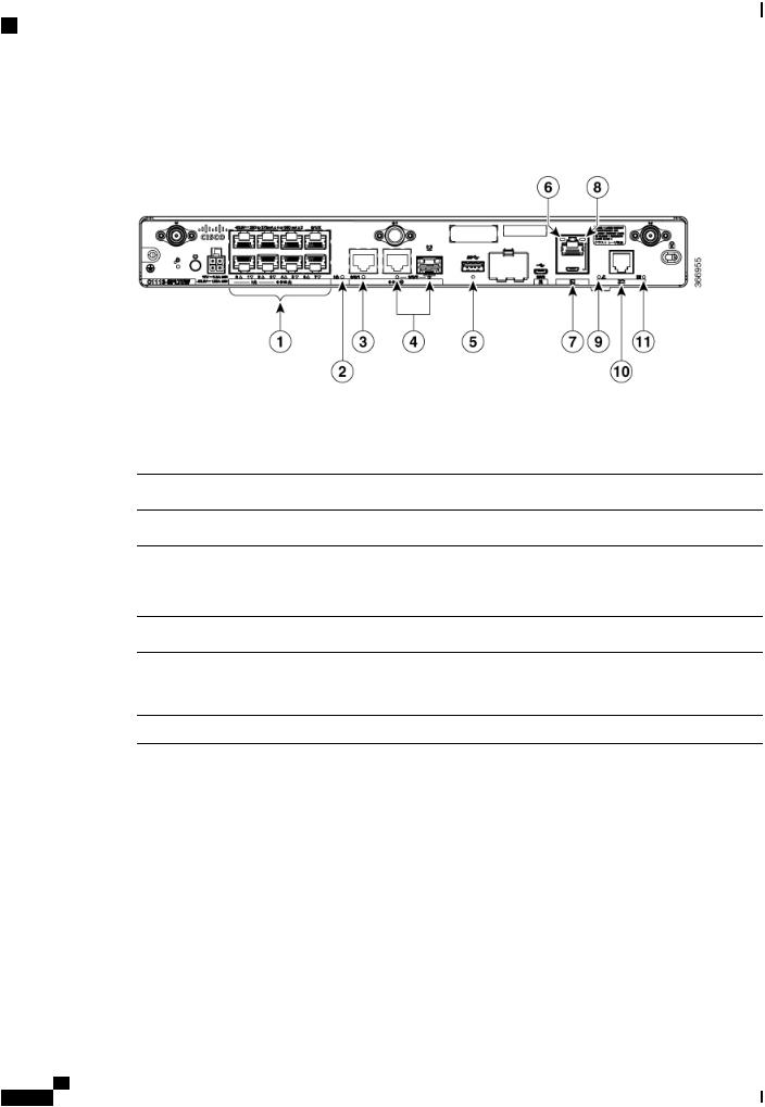
Figure 5: LED Indicators - I/O Side
1 |
GE WAN Ports: 0-7 |
2 |
PoE LED |
|
(0,2,4,6 at the top and |
|
|
|
1,3,5,7 at the bottom) |
|
|
3 |
GE1 LED |
4 |
GE0 LED |
5 |
USB LED |
6 |
RJ-45 Console LED |
7 |
USB Console |
8 |
Micro USB Console LED |
9 |
CD LED |
10 |
DSL |
11 |
DATA LED |
|
|
Table 1: LED Indicators - Description |
|
|
|
Port |
LED Color |
Description |
Location |
Cisco Logo |
Blue |
Bezel illuminated Cisco |
Bezel side |
|
|
logo. Indicates router |
|
|
|
power is good. |
|
Hardware Installation Guide for the Cisco 1100 Series Integrated Services Router
6

Overview of Cisco 1000 Series Integrated Services Routers
Hardware Features
Port |
LED Color |
Description |
Location |
STATUS |
Green and Amber |
Steady Green - System |
Bezel side. All models. |
(System Status) |
|
operates normally |
|
|
|
|
|
|
|
Off—System is not out of |
|
|
|
reset; or BIOS image is |
|
|
|
not loadable. |
|
|
|
Blinking Amber — |
|
|
|
BIOS/Rommon is |
|
|
|
booting. |
|
|
|
Steady Amber — |
|
|
|
BIOS/Rommon has |
|
|
|
completed booting, and |
|
|
|
the system is at the |
|
|
|
Rommon prompt or |
|
|
|
booting the platform |
|
|
|
software. |
|
VPN OK |
Green |
Off—No tunnel. |
Bezel side |
|
|
Steady On— at least one |
|
|
|
tunnel is up |
|
LTE RSSI/Mode |
Green and Amber |
No LEDs On—No |
Bezel Side |
|
|
Service |
|
|
|
1 LED On— RSSI is |
|
|
|
under -100dBm |
|
|
|
2 LEDs On—Low RSSI, |
|
|
|
-99dbm <> -90dBm |
|
|
|
3 LEDs On— Medium |
|
|
|
RSSI -89dBm<> -70dBm |
|
|
|
4 LEDs On—High RSSI, |
|
|
|
> -69dBm |
|
Green— LTE
Amber— 3G
Hardware Installation Guide for the Cisco 1100 Series Integrated Services Router
7

Overview of Cisco 1000 Series Integrated Services Routers
Hardware Features
Port |
LED Color |
Description |
Location |
GPS |
Green and Amber |
Amber— Assisted GPS |
Bezel Side |
|
|
(Reserved for Future Use) |
|
|
|
Green—Standalone GPS |
|
|
|
Off— GPS not |
|
|
|
configured |
|
|
|
On— GPS configured |
|
|
|
Blink— GPS Acquiring |
|
LTE DATA/SIM |
Green and Amber |
Single LTE Modem (one |
Bezel Side |
|
|
modem with SIM |
|
|
|
switch-over capability) |
|
|
|
Off— Modem not up or |
|
|
|
modem up and no SIM |
|
|
|
Amber Steady On— |
|
|
|
Modem up, SIM installed |
|
|
|
but not active. |
|
|
|
Green Steady On— |
|
|
|
Modem up, SIM installed |
|
|
|
and active. |
|
|
|
Green Blink— LTE data |
|
|
|
activity. |
|
WLAN |
Green, Red, and Amber |
Green— Normal |
Bezel side |
|
|
operating condition with |
|
|
|
at least one wireless client |
|
|
|
association. |
|
|
|
Red—Ethernet link is not |
|
|
|
operational or Ethernet |
|
|
|
failure. |
|
|
|
Amber—Software |
|
|
|
upgrade is in progress. |
|
Ethernet Switch GE LAN |
Green |
Off— No link |
I/O side |
Ports, Non-PoE |
|
Steady On— link |
|
|
|
|
|
|
|
Blink— TXD/RXD data |
|
Hardware Installation Guide for the Cisco 1100 Series Integrated Services Router
8

Overview of Cisco 1000 Series Integrated Services Routers
Hardware Features
Port |
LED Color |
Description |
Location |
Ethernet Switch GE LAN |
Green and Amber |
Off— No link, no device |
I/O side |
Ports, with PoE |
|
powered, PD denied |
|
|
|
power, power delivery |
|
|
|
fault PoE administratively |
|
|
|
disabled. |
|
|
|
Green Steady On— link; |
|
|
|
if PoE device, power is |
|
|
|
enabled. |
|
|
|
Green Blink— |
|
|
|
TXD/RXD data |
|
|
|
Amber - PoE Fault |
|
GE WAN Ports |
Green |
Off— No link |
I/O side |
|
|
Steady On— link |
|
|
|
Blink— TXD/RXD data |
|
DSL CD |
Green |
Off— Shut |
I/O Side |
|
|
Green Blink— Training, |
|
|
|
or no shut and cable |
|
|
|
disconnected. |
|
|
|
Green Steady On— |
|
|
|
Trained |
|
PoE OK |
Green |
Green Steady On— |
I/O Side |
|
|
-53.5V PoE power supply |
|
|
|
connected and all |
|
|
|
powered port operating |
|
|
|
normally. |
|
|
|
Off — No -53.5V PoE |
|
|
|
power supply connected |
|
|
|
to router. |
|
DSL Data |
Green |
Off— No Data Activity |
I/O Side |
|
|
Green Blink— TX/RX |
|
|
|
Data |
|
Hardware Installation Guide for the Cisco 1100 Series Integrated Services Router
9

Overview of Cisco 1000 Series Integrated Services Routers
Slots and Interfaces
Port |
LED Color |
Description |
Location |
Console/AUX |
Green and Amber |
Green On— Console |
I/O side |
|
|
enabled. |
|
|
|
Amber On— AUX |
|
|
|
enabled. |
|
USB Console |
Green |
Off— No USB device |
I/O side |
|
|
discovered. |
|
|
|
On— USB device |
|
|
|
discovered. |
|
USB |
Green |
Off: No USB device |
I/O Side |
|
|
discovered. |
|
|
|
On: USB device |
|
|
|
discovered. |
|
Reset Button
The actuation of the Reset button is only recognized during Rommon boot, that is, as the router comes to the Rommon prompt.
The Reset button does not require much force to be actuated. The Reset button should be actuated only with a small implement such as the tip of a pen or a paper clip. When the Reset button is pressed at startup, the system LED will turn green.
For more information, see the "Reset Overview" section of the Cisco 1100 Series Software Configuration Guide.
Slots and Interfaces
About Slots, Subslots, and Port Numbering
Cisco 1100 Series ISRs do not support physical and removable modules. It has only one slot, that is, slot 0. Slot 0 is the motherboard and not removable. It is reserved for integrated ports. The front panel GE ports (or native interface ports) always reside in slot 0 and bay 0. The ports are called Gigabitethernet 0/0/0 and Gigabitethernet 0/0/1.
Each interface type has its own 'bay', and port is a unique port of an interface type.
In most cases, the router designates its interfaces using a 3-tuple notation that lists the slot, bay, and port. The 3-tuple value is zero based. An example of a 3-tuple is 0/1/2. This refers to slot 0, the second bay in slot 0 (the first bay is 0 so the second bay is 1), and the third port in bay 1. See this section for more examples.
Hardware Installation Guide for the Cisco 1100 Series Integrated Services Router
10
Overview of Cisco 1000 Series Integrated Services Routers
Specification
Table 2: Slot, Bay, and Port Numbering |
|
|
|
3- Tuple Example |
Slot |
Bay |
Port |
0/1/2 |
0 |
2nd |
3rd |
0/0/1 |
0 |
1st |
2nd |
Subslot/Bay Numbering
All interfaces are integrated interfaces. There is only one Bay, and the interface 'Type' is defined by a slot number. In this example there is only one slot, 0, and each interface is a bay:
Bay 0 Ethernet WAN
Bay 1 Ethernet LAN (Switch)
Bay 2 LTE
Bay 3 DSL
Bay 4 WiFi
Chassis type: C1117-4PLTEEAWE
Slot Type State Insert time (ago)
--------- ------------------- --------------------- -----------------
0 C1117-4PLTEEAWE ok 00:05:58 0/0 C1117-1x1GE ok 00:03:03 0/1 C1117-ES-4 ok 00:03:01 0/2 C1117-LTE ok 00:02:52 0/3 C1117-VADSL-A ok 00:01:56
0/4 ISR-AP1100AC-E ok 00:03:13
Specification
The following table provide Cisco 1100 ISR specification:
Table 3: Cisco 1100 Series ISR Specification |
|
Description |
Specification |
Physical Properties |
|
Dimensions (H x W x D) |
Non-LTE models: |
|
H x W X D = 1.75 x 12.7 x 9.03 in. (42 x 323 x |
|
230mm) (includes rubber feet) |
|
LTE models: |
|
H x W X D = 1.75 x 12.7 x 9.6 in. (44 x 323 x 244 |
|
mm) (includes rubber feet) |
Weight with AC PS (w/o modules) |
5.5 Lbs. (2.5 kg) maximum |
AC Input Power |
|
Hardware Installation Guide for the Cisco 1100 Series Integrated Services Router
11

Overview of Cisco 1000 Series Integrated Services Routers
Specification
Description |
Specification |
Input voltage |
Universal 100 to 240 VAC |
Frequency |
50-60 Hz |
Input current |
PoE not enabled: 0.82A maximum |
|
PoE enabled: 1.55A Maximum |
Surge current |
90 A peak and less than 8 Arms per half cycle |
Ports |
|
Micro USB Port |
One RJ-45: Separate console port |
USB port |
USB 3.0 Type A host port |
|
USB devices supported: |
|
• USB flash memory |
Console port |
One USB 5-pin micro Type B: Console management |
|
connectivity |
10/100/1000 Gigabit Ethernet |
Two GE ports allocated among RJ45 and SFP as: |
|
One combo port with 10/100/1000RJ-45 Ethernet |
|
port or SFP Ethernet port (labeled GE0/0/0) |
|
One dedicated 10/100/1000RJ-45 Ethernet port |
|
(labeled GE0/0/1) |
Wireless VLANs |
32 (encrypted and non-encrypted VLANs) |
Wireless specifications |
2x2 .11ac Wave 2 |
Default and maximum DRAM |
4GB |
Default and maximum flash |
4GB |
Inline PoE |
4 ports for -8P PIDs, 2 ports for -4P PIDs |
|
802.3af-compliant PoE or 802.3at-compliant PoE+ |
Acoustic for Cisco 1100 Series ISRs |
Not Applicable - Fanless design |
Hardware Installation Guide for the Cisco 1100 Series Integrated Services Router
12

Overview of Cisco 1000 Series Integrated Services Routers
Specification
Description |
Specification |
Approvals and compliance
• Emission
• 47 CFR Part 15
• ◦CISPR 32 Edition 2
◦EN 300 386 V1.6.1
◦EN 55032:2012/ AC:2013
◦EN 55032:2015
◦EN61000-3-2 2014
◦EN61000-3-3: 2013
◦FCC §15.21
◦ICES-003 ISSUE 6:2016
◦KN 32: 2015
◦V-2/2015.04
◦V-3/2015.04
◦TCVN 7189: 2009
◦CNS13438: 2006
◦IEC 60950-1
◦EN 60950-1
◦UL 60950-1
◦CSA C22.2 No. 60950-1
• Immunity
◦CISPR24: 2010 + A1: 2015
◦EN 300 386 V1.6.1
◦EN55024: 2010 + A1: 2015
◦KN35: 2015
◦TCVN 7317: 2003
Table 4: Environmental Specification |
|
Description |
Specification |
Environmental |
|
Hardware Installation Guide for the Cisco 1100 Series Integrated Services Router
13
Loading...