


SM915

Smontagomme SEMI-AUTOMATICO
Démonte-pneus SEMI-AUTOMATIQUE
SEMI-AUTOMATIC Tyre-Changer
HALBAUTOMATISCHE reifenmontiërgerat
SM 915 TI MAXI JUMBOSM 915 TI MAXI JUMBO
SM 915 TI MAXI JUMBO
SM 915 TI MAXI JUMBOSM 915 TI MAXI JUMBO
Ed. 01/02
Manuale di installazione, uso e manutenzione
Installation, operation and maintenance guide
Manuel d’installation, d’utilisation et d’entretien
Installation, bedienung und wartung
Cod. 3012954

DICHIARAZIONE CE DI CONFORMITA'
CE DECLARATION OF CONFORMITY
DECLARATION DE CONFORMITE CE
CE - ÜBEREINSTIMMUNG
CEMB S.p.a. - Via Risorgimento, 9 - 23826 Mandello del Lario (LC) - IT ALY
dichiara sotto la propria esclusiva responsabilità che il prodotto:
declare on our own responsibility that the product:
Déclare sous son propre responsabilité que le produit:
erklärt unter ihrer eigenen V erantwortung, daß das Erzeugnis:
Smontagomme auto
T yr e Changer
Démonte-pneus pour voitures
Reifenmontiergerät für PKW
al quale questa dichiarazione si riferisce E' CONFORME ALLE SEGUENTI DIRETTIVE:
to which declaration refers is IN CONFORMITY WITH THE FOLLOWING DIRECTIVES:
au quel cette déclaration se rapporte EST CONFORME AUX DIRECTIVES SUIVANTES:
darauf diese Erklärung Bezug nimmt, mit den folgenden Bestimmungen übereinstimmt:
Targhetta
98/37/CEE - 91/368/CEE - 93/68/CEE - 89/336/CEE - 86/217/CEE -
27/404/CEE - 73/23/CEE - EN 91/263/CEE - EN 92/31/CEE - EN 93/97/
CEE - EN 98/13/CEE D.P.R. nr. 459 DEL 24/07/96
ed alle Norme:
as well as to the following norms:
ainsi qu’aux normes suivantes:
und folgender Vorschrift gemäß:
EN 292 - EN 60204-1 - EN 50081-1 - EN 50082-1
Mandello del Lario, 12/07/01
Il modello della presente dichiarazione è conforme a quanto previsto nella Norma EN 45014
The model of present declaration is in conformity with directive EN 45014
Le modèlede cette déclarationest conforme àla Norme EN45014
Das Modell dieser Erklärung übereinstimmt mit der Bestimmung EN 45014
2

Indice Generale - General Index
INTRODUZIONE Pag. 5
1. DESCRIZIONE DELLA MACCHINA Pag. 7
Avvertenze di pericolo e divieti Pag. 8
2. GENERALITA' Pag. 9
2.1 Destinazione d'uso Pag. 9
2.2 Norme generali di sicurezza Pag. 10
3. TRASPORTO Pag. 11
4. DISIMBALLO Pag. 11
5. INSTALLAZIONE Pag. 12
5.1 Spazio necessario Pag. 12
5.2 Posizionamento e montaggio Pag. 13
5.3 Messa in servizio Pag. 16
5.4 Test di funzionamento Pag. 17
INTRODUCTION Page 5
1. DESCRIPTION OF THE MACHINE Page 7
Danger and prohibition warning signs Page 8
2. GE NER AL Page 9
2.1 Intended use Page 9
2.2 General safety precautions Page 10
3. TRANSPORT Page 11
4. UNPACKING Page 11
5. INSTALLATION Page 12
5.1 Space required Page 11
5.2 Positioning and assembly Page 13
5.3 Commissioning Page 16
5.4 Operating tests Page 17
6. USO Pag. 19
6.1 Stallonatura Pag. 21
6.2 Smontaggio Pag. 23
6.3 Montaggio Pag. 27
7. GONFIAGGIO Pag. 31
7.1 Gonfiaggio con pistoletta Pag. 31
7.2 Gonfiaggio con dispositivo GT Pag. 35
8. RIPOSIZIONAMENTO Pag. 39
9. ACCANTONAMENTO Pag. 40
10. ROTTAMAZIONE Pag. 40
11. MANUTENZIONE Pag. 41
11.1 Avvertenze generali per la manutenzione Pag. 41
12. TABELLA GUASTI RIMEDI Pag. 45
6. OPERATION Page 19
6.1 Breaking the bead Page 22
6.2 Removing the tyre Page 24
6.3 Mounting the tyre Page 28
7. INFLATING Page 32
7.1 Inflating with airline gauge Page 32
7.2 Inflating with GT system Page 36
8. MOVING Page 39
9. STORAGE Page 40
10. SCRAPPING Page 40
11. MAINTENANCE Page 41
11.1 General Maintenance warning Page 41
12. TROUBLE-SHOOTING Page 45
13. DATI TECNICI Pag. 47
14. SCHEMI ELETTRICI E PNEUMATICI Pag. 48
13. TECHNICAL DATA Page 47
14.
ELECTR. AND PNEUM. DIAGRAMS Page 48
3

Inhalt - Index Général
INTRODUCTION Page 5
1. DESCRIPTION DE LA MACHINE Page 7
Avis de danger et interdictions Page 8
2. GENERALITES Page 9
2.1 Destination Page 9
2.2 Normes générales de sécurité Page 10
3. TRANSPORT Page 11
4. DEBALLAGE Page 11
5. INSTALLATION Page 12
5.1 Espace nécessaire Page 12
5.2 Positionnement et montage Page 13
5.3 Mise en marche Page 16
5.4 Essai de fonctionnement Page 17
EINFÜHRUNG Seite 5
1.BESCHREIBUNG DER MASCHINE Seite 7
Gefahrenhinweise und Verbote Seite 8
2.ALLGEMEINES Seite 9
2.1 Verwendungszweck Seite 9
2.2 Allgemeine Sicherheitsvorschriften Seite 10
3.TRANSPORT Seite 11
4.AUSPACKEN DER MASCHINE Seite 11
5.INSTALLATION Seite 12
5.1 Platzbedarf Seite 12
5.2 Aufstellung und Montage Seite 13
5.3 Inbetriebnahme Seite 16
5.4 Funktionstest Seite 17
6. UTILISATION Page 19
6.1 Décollage du pneu Page 22
6.2 Démontage Page 25
6.3 Montage Page 29
7 GONFLAGE Page 33
7.1 Gonflage avec pistolet Page 33
7.2 Gonflage avec système GT Page 37
8. REPOSITIONNEMENT Page 39
9. MISE EN ATTENTE Page 40
10. MISE A’ LA FERRAILLE Page 40
11. ENTRETIEN Page 41
11.1 Remarques générales pour l’entretien Page 41
12. MAUVAIS FONCTIONN. CAUSES - REMEDES Page 45
6.BETRIEB Seite 19
6.1 Abdrücken Seite 22
6.2 Reifenabnahme Seite 26
6.3 Reifenmontage Seite 30
7.AUFPUMPEN Seite 34
7.1 Aufpumpen mit Druckluftpistole Seite 34
7.2 Aufpumpen mit GT-System Seite 38
8.NEUPOSITIONIEREN Seite 39
9.EINLAGERUNG Seite 40
10.VERSCHROTTUNG Seite 40
11.WARTUNG Seite 42
11.1 Allgemeine Wartungsanweisungen Seite 42
12.TABELLE DER BETRIEBESSTORUNGEN
UND IHRE BEHEBEUNG Seite 45
13. DONNES TECHNIQUES Page 47
14. SCHEMAS ELECTRIQUE ET PNEUMATIQUE Page 48
4
13.TECHNISCHE DATE Seite 47
14. SCHALT- UND DRUCKLUFT PLÄNE Seite 48

INTRODUZIONE
Vi ringraziamo per aver acquistato un prodotto della Nostra linea di smontagomme semi-automatici. La macchina è realizzata attraverso l’applicazione dei migliori principi in rispetto al concetto di qualità.
Per un corretto funzionamento e per una lunga durata sarà sufficiente osservare le semplici istruzioni contenute nel presente manuale che dovrà essere letto e compreso nel modo più completo in ogni sua parte.
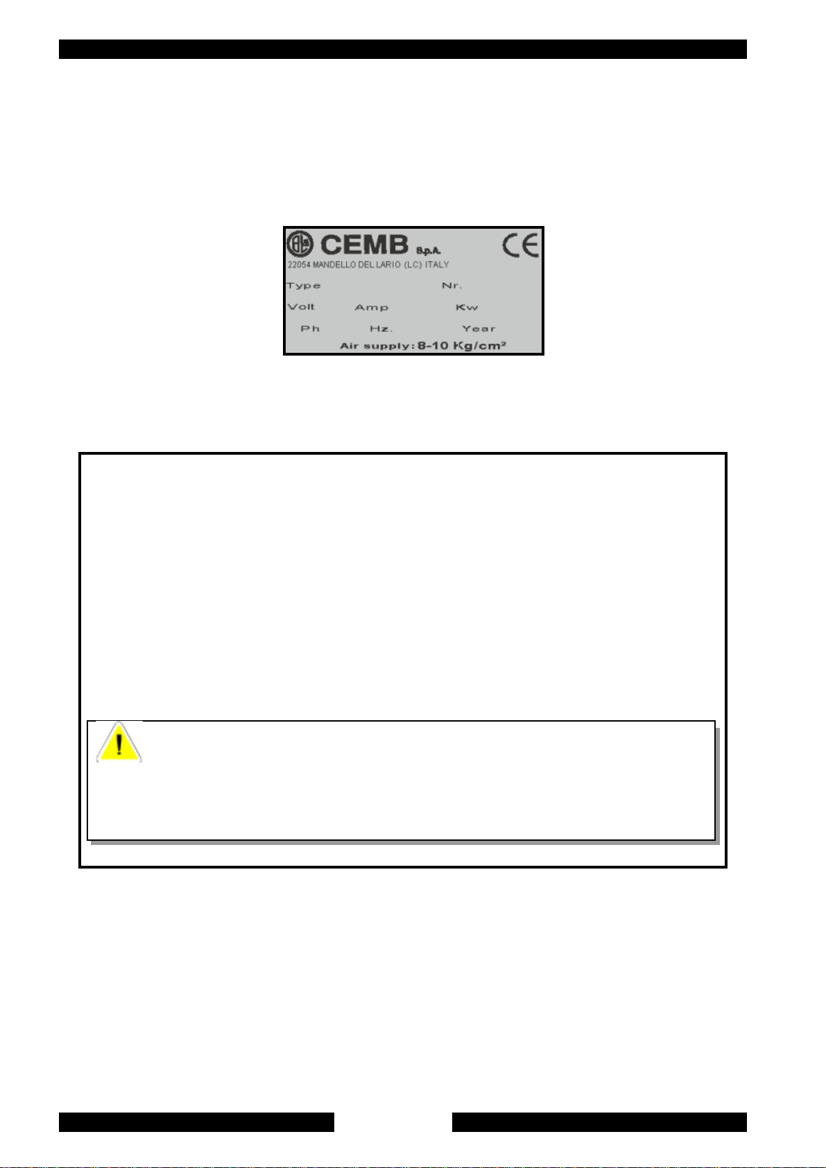
ANAGRAFICA DELLO SMONTAGOMME
Una completa descrizione del “Modello dello Smontagomme” e il “N.ro di Matricola” faciliterà il servizio della Nostra assistenza e la spedizione di parti di ricambio. Per maggiore chiarezza e comodità ricordiamo i dati del Vostro smontagomme
nel riquadro sottostante. Qualora vi fossero delle discordanze fra i dati riportati nel presente manuale e quelli sulla targhetta
applicata allo smontagomme, faranno fede quelli sulla targhetta.
INTRODUCTION
Thank you for purchasing a product from the line of semi-automatic tyre changers. The machine has been manufactured in
accordance with the very best quality principles. Follow the simple instructions provided in this manual to ensure the correct
operation and long life of the machine. Read the entire manual thoroughly and make sure you understand it.
TYRE CHANGER IDENTIFICATION DATA
A complete description of the “Tyre Changer Model” and the “Serial number” will make it easier for our technical assistance to
provide service and will facilitate delivery of any required spare parts. For clarity and convenience, we have inserted the data
of your tyre changer in the box below. If there is any discrepancy between the data provided in this manual and that shown on
the plate fixed to the tyre changer, the latter should be taken as correct.
INTRODUCTION
Nous vous remercions d’avoir choisi un produit de la ligne des démonte-pneus semi-automatiques. La réalisation de ces
machines a été soignée dans les moindres détails pour vous offrir des produits de qualité.
Pour un fonctionnement correct et une longue durée, il suffit d’observer les instructions de ce manuel qui devront être lues
avec beaucoup d’attention pour être bien comprises.
DONNEES DU DEMONTE-PNEUS
Une description complète du “Modèle du démonte-pneus” et le “Numéro de Matricule” faciliteront le service après-vente et
l’expédition d’éventuelles pièces de rechange. Pour plus de clarté, nous vous rappelons, ci-dessous, les données de votre
démonte-pneus. Si les données de ce manuel et celles de la plaquette appliquée sur le démonte-pneus ne correspondent pas,
ce sont celles de la plaquette qui font foi.
EINFÜHRUNG
Wir danken Ihnen für Ihr Vertrauen, das Sie uns mit dem Kauf eines der halbautomatischen Reifenmontiergeräte bewiesen haben. Die
Maschine wurde unter Anwendung der besten Verfahrenstechniken und unter Berücksichtigung höchster Qualitätskriterien gebaut.
Zur fachmännischen Bedienung und im Hinblick auf eine maximale Lebensdauer genügt es, die einfachen Bedienungsanweisungen zu
befolgen, die in diesem Handbuch enthalten sind, das wir Sie aufmerksam zu lesen bitten.
HERSTELLERDATEN DES REIFENMONTIERGERÄTES
Eine komplette Beschreibung Ihres Reifenmontiergeräte-Modells sowie die Angabe der Matrikelnummer vereinfachen uns den
Kundendienst sowie den Versand von Ersatzteilen. Zu Ihrer Information geben wir die Daten Ihres Reifenmontiergerätes untenstehend
an. Falls zwischen den unten angegebenen Daten und denjenigen, die Sie auf dem Typenschild Ihres Reifenmontiergerätes finden,
Unterschiede bestehen, gelten die Angaben auf dem Typenschild.
5
COSTRUTTORE /
MANUFACTURER /
CONSTRUCTEUR / HERSTELLER
Casa costruttrice /
Indirizzo /
Address: /
Il presente manuale costituisce parte integrante del prodotto.
Prima di utilizzare lo smontagomme, leggere attentamente le avvertenze e le istruzioni contenute nel presente
libretto in quanto forniscono importanti indicazioni riguardanti la sicurezza d’uso e la manutenzione.
This manual is an integral part of the product.
Before using the tyre changer, read carefully the warnings and instructions contained in this manual since
they provide important information on operating safety and maintenance.
Manufactured by: /
Maison constructrice: / Herstellerfirma: CEMB Spa
Adresse / Adresse: Via Risorgimento, 9 - 23826 Mandello del Lario (LC) - IT ALY
Le présent manuel fait partie intégrante du produit.
Avant d’utiliser le démonte-pneus, lire attentivement les instructions et les remarques du présent manuel
car elles fournissent des indications importantes sur la sécurité d’utilisation et l’entretien.
Dieses Handbuch ist Bestandteil des Produktes.
Bevor Sie das Reifenmontiergerät zum ersten Mal benützen, lesen Sie bitte aufmerksam die darin enthaltenen Anweisungen,
denn sie enthalten wichtige Hinweise zur Betriebssicherheit und Wartung.
Conservare con cura questo manuale per ogni ulteriore consultazione
Keep this manual for further reference.
Conserver très soigneusement ce manuel pour le consulter si nécessaire.
Bewahren Sie dieses Handbuch sorgfältig auf, damit Sie es jederzeit wieder konsultieren können!
6

1. DESCRIZIONE DELLA MACCHINA
1. DESCRIPTION DE LA MACHINE - BESCHREIBUNG DER MASCHINE
- DESCRIPTION OF THE MACHINE
G) Griffe di bloccaggio
I) Torretta integrale
L) Pistoletta di gonfiaggio
M) Braccio operante
N) Palo orizzontale
P) Palo verticale
Q) Alimentazione aria
R) Stallonatore
S) Appoggi ruota
T) Leva alzatalloni
U) Pedale comando stallonatore
V) Pedale comando griffe
Z) Pedale comando invertitore
Y) Piatto autocentrante
K) Leva bloccaggio
G) Clamps
I) Mounting head
L) Airline gauge
M) Mounting bar
N) Horizontal arm
P) Vertical arm
Q) Air supply
R) Bead breaker
S) Wheel support
T) Bead lifting lever
U) Bead breaker control pedal
V) Clamp control pedal
Z) Reverser control pedal
Y) Turntable
K) Locking lever
G) Mors de blocage
I) Tête de montage
L) Pistolet de gonflage
M) Barre de montage
N) Bras horizontal
P) Bras vertical
Q) Raccord air comprimé
R) Détalonneur
S) Supports de roue
T) Levier démonte-pneus
U) Pédale de commande du détalonneur
V) Pédale de commande des mors
Z) Pédale de commande de l’inverseur
Y) Plateau à centrage automatique
K) Levier de blocage
Fig. 1/ Abb. 1
G) Spannklauen
I) Montierfuß
L) Reifenfülldruckgerät
M) Werkzeugarm
N) Horizontalstab
P) Kipparm
Q) Druckluftanschluß
R) Abdrückblatt
S) Radanschläge
T) Hebel zur Wulstanhebung
U) Steuerpedal Abdrückblatt
V) Steuerpedal Spannklauen
Z) Steuerpedal Wendegetriebe
Y) Zentriertisch
K) Sperrhebel
7
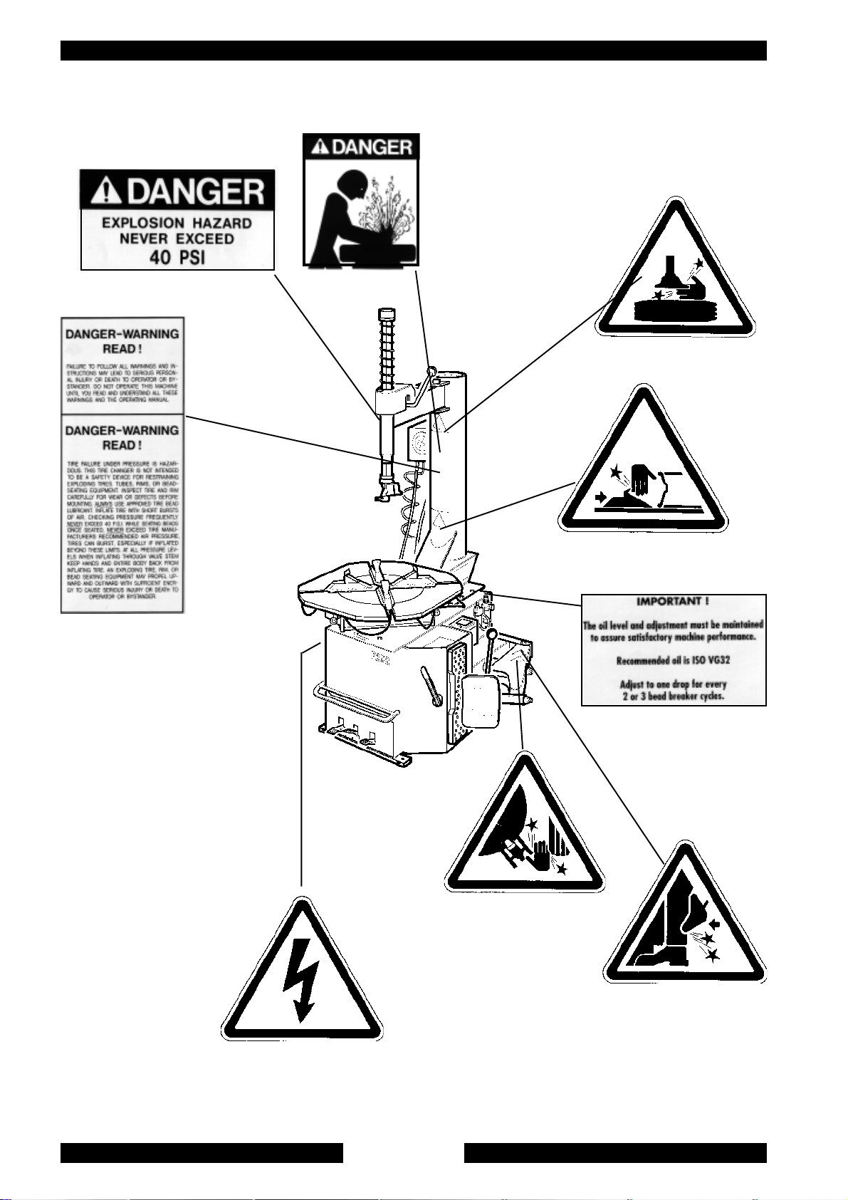
AVVERTENZE DI PERICOLO -
DANGER WARNING SIGNS -
AVIS DE DANGER - GEFAHRENHINWEISE
Cod. 3001422
Cod. 3002468
Cod. 3001104
Cod. 3005416
Cod. 3005413
Cod. 3005410
Cod. 3006964
Cod. 3005415
Cod. 3005414
Fig. 2
8

2. GENERALITÀ
2.1 DESTINAZIONE D’USO.
• Lo smontagomme semi-automatico è stato progettato e realizzato esclusivamente per lo smontaggio e il montaggio
dei pneumatici dai/sui cerchi con dimensioni da 12" a 26" e diametro max. 1200 mm.
Qualsiasi altro uso è da considerarsi improprio e quindi irragionevole
• In particolare
esplicati in questo manuale e quindi impropri, erronei ed irragionevoli.
IL COSTRUTTORE
non può essere considerata responsabile per eventuali danni causati da usi non
2. GENERAL
2.1 INTENDED USE
• The semi-automatic tyre changer has been designed and manufactured exclusively for removing and mounting
tyres from/onto rims from 12" to 26" and a maximum diameter of 1200 mm.
Any other use is to be considered incorrect and unreasonable.
•In particular The Manufacturer cannot be held responsible for any damage caused through the use of this tyre changer for
purposes other than those specified in this manual, and therefore inappropriate, incorrect and unreasonable.
2. GENERALITES
2.1 DESTINATION
• Le démonte-pneus semi-automatique a été projeté et réalisé exclusivement pour le démontage et le montage des
pneus des/sur les jantes avec dimensions de 12" à 26" et diamètre max de 1200 mm.
Toute autre utilisation doit être considérée impropre et donc irraisonnée.
•
Le constructeur
sont pas expliquées dans ce manuel et par conséquent impropres et incorrectes.
2. ALLGEMEINES
2.1 VERWENDUNGSZWECK
Das halbautomatische Reifenmontiergerät wurde ausschließlich zum Ab- und Neumontieren von Reifen von/auf Felgen geschaffen von 12"
bis 26" und einem Durchmesser bis zu 1200 mm,.
Jede anderweitige Verwendung ist unsachgemäß und deshalb unzulässig !
Der Hersteller haftet daher nicht, wenn durch Verwendungen, die in diesem Handbuch nicht vorgesehen und deshalb unsachgemäß, falsch
und unzulässig sind, Schäden entstehen.
ne peut pas être considérée responsable de dommages éventuels causés par des utilisations qui ne
9

2.2 NORME GENERALI DI SICUREZZA.
L’uso dello smontagomme è consentito solo ed esclusivamente a personale esperto, appositamente
addestrato ed autorizzato.
• Ogni e qualsiasi manomissione o modifica dell’apparecchiatura non preventivamente autorizzate dal costruttore
sollevano quest’ultimo da ogni responsabilità per danni derivati o riferibili agli atti suddetti.
• La rimozione o manomissione dei dispositivi di sicurezza comporta la decadenza immediata della garanzia e la
violazione delle Norme Europee per la Sicurezza.
• Lo smontagomme è corredato di decalcomanie di istruzione ed avvertenze progettate e realizzate per durare nel tempo.
Qualora venissero danneggiate o distrutte, l'utente deve richiederle subito al costruttore utilizzando i codici di pag.8
2.2 GENERAL SAFETY PRECAUTIONS
The tyre changer may only be used by specially trained and authorized expert personnel.
• Any tampering or modification to the equipment carried out without the manufacturer’s prior authorization will free him from
all responsibility for damage caused directly or indirectly by the above actions.
• Removing or tampering with safety devices immediately invalidates the guarantee and is in contravention of European
Safety Standards.
• The tyre changer comes complete with instruction and warning transfers which are designed to be long-lasting.
If they should for any reason be damaged or destroyed, please ask immediately for replacements from the manufacturer
using the codes given on page 8.
2.2 NORMES GENERALES DE SECURITE
L’utilisation du démonte-pneus est permise exclusivement à du personnel spécialisé, expressément
formé et autorisé.
• Le constructeur n’est pas responsable des dommages causés par les appareils qui ont été modifiés sans son autorisation
préalable.
• La garantie est immédiatement nulle si des modifications ou des transformations sont apportées aux dispositifs de
sécurité; celles-ci sont une violation des normes européennes pour la sécurité.
• Le démonte-pneus est équipé de décalcomanies d’instructions et d’avis de danger, projetées et réalisées pour durer dans
le temps. Si elles sont endommagées ou détruites, l’utilisateur doit les demander immédiatement au constructeur en
utilisant les codes de la page 8.
2.2 ALLGEMEINE SICHERHEITSNORMEN
Die Verwendung des Reifenmontiergerätes ist nur Personen gestattet, die entsprechende Erfahrung haben,
eingewiesen worden und zum Gebrauch befugt sind.
-Falls Veränderungen oder Eingriffe auf dem Gerät vorgenommen werden, die vom Hersteller nicht zuvor bewilligt worden sind, haftet
dieser nicht für Schäden, die auf diese zurückzuführen sind.
-Die Entfernung oder Veränderung von Sicherheitsvorrichtungen bewirkt den sofortigen Verfall der Garantie und stellt eine Verletzung der
Europäischen Sicherheitsnormen dar.
-Auf dem Reifenmontiergerät wurden Klebeetiketten mit Anweisungen und Warnungen angebracht, durch deren Beachtung die Lebensdauer
des Gerätes verlängert werden kann.
Werden diese beschädigt oder entfernt, müssen sie sofort beim Hersteller unter Angabe der Bestell-Nummern von Seite 8 angefordert
werden
10
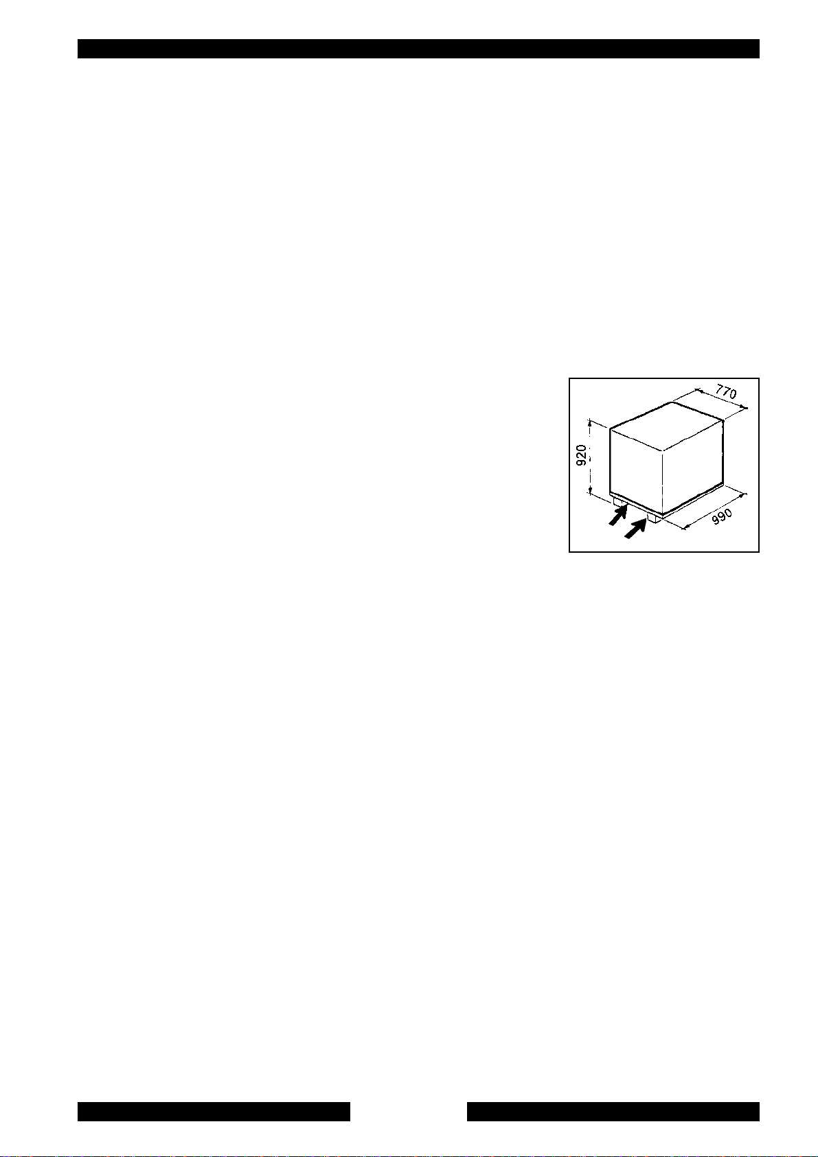
3. TRASPORTO
• Lo smontagomme deve essere trasportato nell'imballo originale e mantenuto nella posizione indicata sull'imballo stesso.
• Lo spostamento della macchina imballata deve essere effettuato inforcando con un carrello elevatore di adeguate
capacità, nei punti indicati dalla figura 3.
3. TRANSPORT
• The tyre changer must be transported in its original packaging and kept in the position shown on the package itself.
• The packaged machine may be moved by means of a fork lift truck of suitable capacity. Insert the forks at the points shown
in figure 3.
3. TRANSPORT
• Le démonte-pneus doit être transporté dans son emballage et maintenu dans la position indiquée sur l’emballage même.
• La machine emballée doit être déplacée sur les fourches d’un chariot élévateur d’une capacité
appropriée, enfilées aux points indiqués sur la figure 3.
3. TRANSPORT
Das Reifenmontiergerät darf nur in seiner Originalverpackung und in der auf der
Verpackung angegebenen Position transportiert werden.
Die verpackte Maschine darf nur mit einem dazu geeigneten Gabelstapler angehoben und
transportiert werden, wobei die Gabeln an den in
Abb. 3 angegebenen Punkten einzuschieben sind.
4. DISIMBALLO
Togliere il cartone di protezione e il sacchetto in nylon
Assicurarsi dell’integrità dell’apparecchio controllando che non vi siano parti visibilmente danneggiate o
mancanti facendo riferimento alla fig. 1
In caso di dubbio non utilizzare la macchina e rivolgersi al proprio rivenditore.
Kg.220
Fig. 3
4. UNPACKING
Remove the protective cardboard and the nylon bag.
Check that the equipment is in perfect condition, making sure that no parts are damaged or missing. Use fig. 1 for
reference.
If in doubt do not use the machine and contact your retailer.
4. DEBALLAGE
Enlever le carton de protection et le sac en nylon.
Contrôler qu’il n’y ait pas de parties visiblement endommagées ou manquantes en se référant à la figure 1.
En cas de doute, ne pas utiliser la machine et s’adresser au revendeur autorisé.
4. AUSPACKEN DER MASCHINE
Schutzkarton und Plastikbeutel entfernen.
Kontrollieren, ob das Gerät intakt ist, ob keine sichtbaren Beschädigungen vorhanden sind oder Teile fehlen, siehe dazu
Abb.1.
Im Zweifelsfalle die Maschine nicht benützen und den Verkäufer benachrichtigen.
11

5. INSTALLAZIONE
5.1 SPAZIO NECESSARIO
Al momento della scelta del luogo di installazione, è necessario osservare le normative vigenti per
la sicurezza sul lavoro
• Lo smontagomme semi-automatico, necessita di collegamenti con la rete elettrica e con l’impianto di aria compressa.
E’ perciò opportuno installare la macchina in prossimità di tali fonti energetiche.
• Inoltre, sul luogo prescelto per l’installazione, devono essere disponibili almeno gli spazi indicati dalla figura 4/A per
permettere il regolare funzionamento di tutte le sue parti senza alcuna limitazione.
• Se la macchina viene installata all'aperto è necessario che sia protetta da una tettoia.
Nel caso lo smontagomme sia del tipo a motore elettrico è proibito l'uso in atmosfere esplosive a meno
che non si tratti di una apposita versione.
5. INSTALLATION
5.1 SPACE REQUIRED
When choosing the place of installation be sure that it complies with current safety at work regulations.
•The semi-automatic tyre changer must be connected to the mains electric power supply and the compressed air system.
It is therefore advisable to install the machine near these power sources.
•The place of installation must also provide at least the space shown in figure 4/A so as to allow all parts of the machine to
operate correctly and without any restriction.
•If the machine is installed outside it must be protected by a lean-to.
The tyre changer with electric motor cannot be used in explosive atmospheres, unless it is a proper version.
5. INSTALLATION
5.1 EMPLACEMENT NECESSAIRE
Au moment du choix du lieu d’installation, observer les normes en vigueur pour la sécurité du travail.
•Le démonte-pneus semi-automatique devra être raccordé au réseau électrique et à l’installation d’air comprimé. Il faudra
donc en tenir compte pour le choix de l’emplacement.
•De plus, dans le lieu d’installation il faudra les espaces nécessaires pour permettre le fonctionnement régulier de toutes les
parties du démonte-pneus, sans aucune limitation (voir fig. 4/A).
•Si la machine doit être installée en plein air, elle devra être protégée par un abri.
Si le démonte-pneus est du type à moteur électrique, son utilisation est interdite près de matières explosives,
à moins qu’il ne s’agisse d’une version appropriée.
5. INSTALLATION
5.1 PLATZBEDARF
Bei der Wahl des Aufstellungsortes müssen die gültigen Bestimmungen zur Sicherheit am Arbeitsplatz beachtet werden.
Das halbautomatische Reifenmontiergerät benötigt Anschlüsse an das Stromnetz und an die Druckluftzufuhr. Deshalb ist es ratsam, die
Maschine in der Nähe dieser Energiequellen aufzustellen.
Zudem muss am gewählten Installationsort mindestens soviel Platz vorhanden sein, wie in Abb. 4/A angegeben ist, so daß der Betrieb aller
Maschinenteile problemlos eingestellt werden kann.
Wird die Maschine im Freien aufgestellt, muß sie durch ein Dach geschützt werden.
Falls das Reifenmontiergerät einen elektrischen Motor aufweist, darf es nicht in Räumen mit Explosionsgefahr
verwendet werden, außer wenn es um eine geeignete Ausführung handelt.
12

5.2 POSIZIONAMENTO E MONTAGGIO
1) Posizionare il palo verticale nell’apposita sede e avvitare le viti di bloccaggio come indicato nel disegno.
2) Serrare la fascetta di bloccaggio
5.2 POSITIONING AND ASSEMBLY
1) Place the vertical arm in its seat and screw the fastening screws as shown in diagram.
2) Tighten the hose clamp.
5.2 POSITIONNEMENT ET MONTAGE
1) Positionner le bras vertical dans son logement et visser les vis de fixation comme indiqué dans le dessin.
2) Serrer le collier de blocage
5.2 AUFSTELLUNG UND MONTAGE
1) Den waagerechten Arm auf den bestimmten Sitz stellen und die Klemmschrauben anziehen (siehe Abbildung)
2) Den Schlauchbinder anziehen.
500 mm
500 mm
500 mm
Fig. 4/A
500 mm
13
Fig. 5

Montaggio e collegamento manometro
• Fissare la scatola manometro al palo verticale tramite le
apposite viti in dotazione.
• Fare passare il tubo di collegamento a spirale (4) nel foro
piccolo situato sul retro della carcassa.
• Collegare il tubo rilsan al raccordo del limitatore di
pressione posto sul pedale di gonfiaggio
Mounting and connecting the manometer
Fix the manometer box to the vertical arm through the proper
screws.
Let the connection spiral hose (4) pass through the small hole
on the back side of the machine body.
Connect the rilsan hose to the union of the pressure limiting
device, situated on the inflating pedal.
Montage et branchement du manomètre
Fixer la boîte manomètre au bras vertical moyennant les vis
fournies.
Laisser passer le tuyau-spirale de connexion (4) par le petit trou qui se trouve arrière au bâti.
Brancher le tuyau rilsan au raccord du limitateur de pression sur la pédale de gonflage.
Montage und Verbindung des Manometers
Manometergehäuse am Vertikalausleger durch die dazu bestimmten Schrauben befestigen.
Die Verbindungsspirale (4) durch kleines Loch auf Hinterseite der Maschine schieben lassen.
Rilsanschlauch mit der Verschraubung der Druckbegrenzvorrichtung auf dem Aufpumppedal verbinden.
14

5.3 MESSA IN SERVIZIO
Prima di effettuare gli allacciamenti, accertarsi che le caratteristiche dei propri impianti corrispondano a
quelle richieste dalla macchina.
• Se fosse necessario cambiare la tensione di funzionamento della macchina occorre intervenire sulla morsettiera (Cap. 14schema elettrico)
Interventi sull’impianto elettrico, anche se di lieve entità, richiedono l’intervento di personale
professionalmente qualificato.
• Collegare la macchina all’impianto d’aria compressa tramite l’attacco (Q) sporgente dalla parte posteriore (fig. 6)
• Collegare la macchina alla rete elettrica che deve essere dotata di fusibili di linea, di una buona presa a terra
come da norme vigenti e collegata ad un interruttore automatico di alimentazione (differenziale) tarato a 30 mA.
NOTA: Qualora lo smontagomme venga fornito senza spina elettrica, sarà cura dell'utente montarne una(almeno 16 A)
adeguata alla tensione della macchina e secondo le normative vigenti.
5.3 COMMISSIONING
Before making the connections, check that the characteristics of your systems correspond to those required
by the machine.
•If you have to change the machine’s operating voltage, make the necessary adjustments to the terminal board (Chap.14)
Even small jobs done on the electrical system must be carried out by professionally qualified personnel.
•Connect the machine to the compressed air system by means of the air connection (Q) that protrudes from the rear section
as shown in the diagram 6.
•Connect the machine to the electric network, which must be provided with line fuses, a good earth plate in compliance
with regulations in force and it must be connected to an automatic circuit breaker (differential) set at 30 mA.
Note: Should the tyre-changer be lacking in electric plug, so the user must set one,which is at least 16 A and which
conforms to the voltage of the machine, in compliance with the regulations in force.
5.3 MISE EN MARCHE
Avant d’effectuer les raccordements, vérifier que les caractéristiques des installations correspondent à celles
demandées par la machine.
•S’il faut changer la tension de fonctionnement de la machine, intervenir sur le bornier (voir schéma électrique Chap. 14).
Les interventions sur l’installation électrique, même si elles sont peu importantes, doivent être effectuées par
du personnel qualifié.
•Raccorder la machine à l’installation d’air comprimé par le raccord (Q) situé à l’arrière (voir figure 6).
•Relier la machine au reseau électrique, qui doit être equipé de fusibles de ligne et d’une prise de terre conformément aux
normes en vigueur. De plus, il faut relier la machine à un interrupteur automatique d’alimentation (différentiel) reglé à 30 mA.
NOTE: Si le demonte-pneus est dépourvu de fiche électrique, l’utilisateur devramonter une fiche qui soit proporsionnée
à la tension de la machine ( au moins 16 A) conformément aux normes en vigueur.
5.3 INBETRIEBNAHME
Vor dem Anschluß muß überprüft werden, ob die Eigenschaften der Betriebsanlagen den von der Maschine
geforderten Werten entsprechen.
-Falls die Betriebsspannung der Maschine geändert werden muß, entsprechend Schaltplan im Kap. 14 Klemmenbrett vorgehen.
(Auch kleinere) Eingriffe an der elektrischen Anlage dürfen nur von Fachpersonal vorgenommen werden.
-Maschine an das Druckluftnetz anschließen, hierzu den Anschlußstutzen (Q) verwenden, der gemäß Abbildung hinten hervorsteht.
Maschine vorschriftsgemäß an das Stromnetz anschließen. Das Stromnetz muß mit Schmelzsicherungen sowie mit einem guten
Erdschluß versehen werden. Dazu muß die Maschine an einen selbstätigen 30mA geeichten Ausschalter (Differential) verbindet
werden.WICHTIG:Wenn das Reifenmontiergerät ohne Steckdose geliefert wird, muß der Verbraucher mindestens eine 16A
Steckdose anschließen. Diese muß an die Spannung der Maschine angemessen und gemäß der gültigen Bestimmungen sein.
15
 Loading...