


Instructions for use 
 I
I
Contents |
Page |
1 - GENERAL...................................................................................................................................................................... |
3 |
|
1.1 |
- GENERAL SAFETY REGULATIONS ............................................................................................................... |
3 |
|
1.1.1 - STANDARD SAFETY DEVICES .......................................................................................................... |
3 |
1.2 |
- FIELD OF APPLICATION ................................................................................................................................. |
3 |
1.3 |
- OVERALL DIMENSIONS ................................................................................................................................. |
3 |
1.4- SPECIFICATION .............................................................................................................................................. |
4 |
|
2 - HANDLING, HOISTING ............................................................................................................................................... |
4 |
|
3 - START-UP .................................................................................................................................................................... |
5 |
|
3.1 |
- ANCHORING .................................................................................................................................................... |
5 |
3.2 |
- ELECTRICAL CONNECTION . ......................................................................................................................... |
5 |
3.3 |
- PNEUMATIC CONNECTION (Versions SE ) ..................................................................................................... |
5 |
3.4 |
- EXTRA SAFETY DEVICES (VERSION SE )..................................................................................................... |
5 |
3.5 |
- ADAPTER MOUNTING .................................................................................................................................... |
5 |
SE2 MOUNTING ........................................................................................................................................................ |
6 |
|
SE2 DISMOUNTING .................................................................................................................................................. |
7 |
|
3.5 |
- WHEEL GUARD ASSEMBLY AND ADJUSTMENT............................................................................................ |
8 |
3.7 |
- SPACER WD ...................................................................................................................................................... |
8 |
4 - CONTROLS AND COMPONENTS ............................................................................................................................. |
8 |
|
4.1 |
- BRAKE PEDAL................................................................................................................................................... |
8 |
4.2 |
- PNEUMATIC LOCKING PEDAL (Version P)...................................................................................................... |
8 |
4.3 |
- AUTOMATIC RIM DISTANCE AND DIAMETER GAUGE ................................................................................. |
9 |
4.4 |
- AUTOMATIC WIDTH GAUGE (OPTIONAL) ..................................................................................................... |
9 |
4.5 |
- AUTOMATIC WHEEL POSITIONING ................................................................................................................ |
9 |
4.6 |
- CONTROL PANEL AND DISPLAY ................................................................................................................. |
10 |
|
4.6.1 CONTROL OF THE FUNCTIONS MENU ............................................................................................. |
11 |
5 - INDICATIONS AND USE OF THE WHEEL BALANCER .......................................................................................... |
12 |
|
5.1 |
- DOUBLE OPERATOR PROGRAM ................................................................................................................. |
12 |
5.2 |
- PRESETTING OF WHEEL DIMENSIONS .................................................................................................... |
12 |
|
5.2.1 - AUTOMATIC PRESETTING ............................................................................................................... |
12 |
|
5.2.1.1 - “AUTOMATIC WIDTH” OPTION........................................................................................................ |
13 |
|
5.2.1.2 - WHEEL ALU-S .................................................................................................................................. |
13 |
|
5.2.2 - MANUAL PRESETTTING .................................................................................................................. |
14 |
5.3 |
- RECALCULATION OF THE UNBALANCE .................................................................................................... |
15 |
5.4 |
- RESULT OF MEASUREMENT ....................................................................................................................... |
15 |
|
5.4.1 - INDICATION OF EXACT CORRECTION POSITION IN ALU-S ........................................................ |
15 |
|
5.4.2 - RESOLUTION OF THE UNBALANCE (SPLIT) .................................................................................. |
16 |
|
5.4.3 - UNBALANCE OPTIMIZATION ........................................................................................................... |
18 |
|
5.4.4 - ALU AND STATIC MODES ................................................................................................................. |
19 |
|
5.4.5 -AUTOMATIC MINIMIZATION OF STATIC UNBALANCE ..................................................................... |
19 |
5.5 |
- ECCENTRICTY MEASUREMENT (OPTION).................................................................................................. |
20 |
6 - SET UP ...................................................................................................................................................................... |
21 |
|
6.1 |
- SELF-DIAGNOSTICS ..................................................................................................................................... |
21 |
6.2 |
- SELF-CALIBRATION ...................................................................................................................................... |
22 |
6.3 |
- SCREEN SAVER............................................................................................................................................. |
23 |
6.4 |
- TYPE OF DISPLAY OF UNBALANCE PHASE ................................................................................................ |
24 |
6.5 |
- AUTOMATIC GAUGES ................................................................................................................................. |
25 |
|
6.5.1 - RIM DISTANCE GAUGE .................................................................................................................... |
25 |
|
6.5.2 - DIAMETER GAUGE ........................................................................................................................... |
25 |
|
6.5.3 - WIDTH GAUGE (OPTIONAL))............................................................................................................. |
26 |
6.6 |
- AMBIENT TEMPERATURE.............................................................................................................................. |
26 |
7 - ERRORS .................................................................................................................................................................... |
27 |
|
7.1 |
- INCONSISTENT UNBALANCE READINGS .................................................................................................. |
28 |
8 - ROUTINE MAINTENANCE ........................................................................................................................................ |
28 |
|
8.1 |
- TO REPLACE THE FUSES.............................................................................................................................. |
28 |
9 - RECOMMENDED SPARE PARTS LIST ..................................................................................................................... |
29 |
|
I 0307_0308 GB - 1
I 0307_0308 GB - 2

1- GENERAL
1.1 - GENERAL SAFETY RECOMMENDATIONS
-The balancing machine should only be used by duly authorized and trained personnel.
-The balancing machine should not be used for purposes other than those described in the instruction manual.
-Under no way should the balancing machine be modified except for those modifications made explicitly by the manufacturer.
-Never remove the safety devices. Any work on the machine should only be carried out by duly authorized specialist personnel.
-Do not use strong jets of compressed air for cleaning.
-Use alcohol to clean plastic panels or shelves (AVOID LIQUIDS CONTAINING SOLVENTS).
-Before starting the wheel balancing cycle, make sure that the wheel is securely locked on the adapter.
-The machine operator should not wear clothes with flapping edges. Make sure that unauthorized personnel do not approach the balancing machine during the work cycle.
-Avoid placing counterweights or other objects in the base which could impair the correct operation of the balancing machine.
1.1.1 - STANDARD SAFETY DEVICES
-STOP push button for stopping the wheel under emergency conditions.
-The safety guard of high impact plastic is with shape and size designed to prevent risk of counterweights from flying out in any direction except towards the floor.
-A microswitch prevents starting the machine if the guard is not lowered and stops the wheel whenever the guard is raised.
1.2 - FIELD OF APPLICATION
The machine is designed for balancing car or motorcycle wheels weighing less than 65 kg. It can be operated within a temperature range of 0° to + 45°C.
It can measure the geometric radial run-out of the wheels (optional)
1.3 - OVERALL DIMENSIONS (42" Protection)
Fig. 1
I 0307_0308 GB - 3

1.4 - SPECIFICATION
Single phase power supply ............................... |
115 - 230 V 50-60 Hz |
Protection class ................................................ |
IP 54 |
Max. power consumption .................................. |
1100 W |
Balancing speed approx.................................... |
180 min-1 |
Cycle time for average wheel (14 Kg) ............. |
(14 Kg) 6 seconds |
Balancing accuracy ........................................... |
0,1 grammi |
Position resolution ............................................. |
± 1.4 ° |
Average noise level ........................................... |
< 70 dB(A) |
Distance rim - machine...................................... |
0 - 280 mm (400 mm can be preset) |
Rim width setting range .................................... |
1.5” ÷ 20” or 40 ÷ 510 mm |
Diameter setting range ...................................... |
10” ÷ 26” or 265 ÷ 665 mm |
Total wheel diameter within guard ..................... |
1067 (42”) |
Total wheel width within guard........................... |
500 (42”) |
Max. wheel weight............................................. |
65 Kg. |
Min/max. compressed air pressure ................... |
7 ÷ 10 Kg/cm2 approx. 0.7 to 1 Mpa; approx. 7 to 10 BAR; |
......................................................................................... |
approx. 100 to 145 PSI. |
2 - HANDLING AND HOISTING
Fig. 2
Fig. 2a
NB: DO NOT HOIST THE MACHINE USING DIFFERENT GRIPS
I 0307_0308 GB - 4

3 - COMMISSIONING
3.1 - ANCHORING
The machine can be operated on any fl at non-resilient fl oor.
Make sure that the machine rests solely on the three support points provided (fi g. 2a).
It is advisable to secure the system to the ground using the specific feet (see Figure 2a) in the event of continual use with wheels weighing over 35 Kg.
3.2 - ELECTRICAL CONNECTION
The machine is supplied with a single phase mains cable plus earth (ground).
The supply voltage (and mains frequency) is given on the machine nameplate. It may NOT be changed. Connection to the mains should always be made by expert personnel.
The machine should not be started up without proper earth (ground) connection.
Connection to the mains should be through a slow acting safety switch rated at 4A (230V) or 10A (115V) .
3.3 - PNEUMATIC CONNECTION (Versions SE)
For operation of the spindle with pneumatic locking (costant thrust air spring) connect the balancing to the compressed air main. The connection fi tting is located at the back of the machine. At least 7 Kg/cm2 (~ 0.7 MPa; ~ 7 BAR; ~ 100 PSI) pressure is needed for correct operation of the release device.
3.4 - EXTRA SAFETY DEVICES (VERSION SE)
- Wheel always locked even when there is pressure failure during the balancing cycle.
- Always actuate the unlocking control pedal with the machine stationary in order to avoid stress and abnormal wear on the adapter.
3.5 - ADAPTER MOUNTING
The balancing machine is supplied complete with cone adapter for fastening wheels with central bore. Other optional fl anges can be mounted once the terminal part is removed (also see enclosed brochures)
N.B. Carefully clean the coupling surfaces before performing any operation
a) DISMOUNTING THREADED END PIECE
A
Fig. 3 |
B |
|
a)Back-off screw B and remove threaded end-piece A.
b)Fit the new adapter
I 0307_0308 GB - 5

SE2-Mounting
a |
|
|
b |
|
1 |
|
|
|
- |
|
|
|
|
2 |
mm |
|
|
|
|
c |
|
|
d |
e |
f |
g |
|
0 |
mm |
|
SE2_ 0140
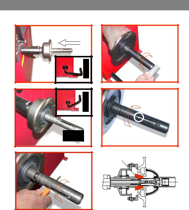
SE2-Dismounting
|
360° |
a |
b |
c |
d |
|
Cone |
e
-Quando possibile, centrare le ruote con cono dall'interno (vedi disegno).
-Evitare di usare il manicotto RL con cerchi di ferro.
-Whenever possible, centre the wheels with the cone from the inside (see the drawing).
-Avoid using the RL sleeve with metal rims.
-Lorsque c’est possible, centrer les roues avec le cône de l’intérieur (voir dessin).
-Eviter d’utiliser le manchon RL avec les jantes en fer.
-Wenn möglich, die Räder mit Konus von Innen heraus zentrieren (siehe Zeichnung).
-Bei Eisenfelgen die Verwendung der Muffe RL vermeiden.
-Siempre que sea posible, centrar las ruedas con cono desde dentro (véase dibujo).
-Evitar usar el manguito RL con llantas de hierro.
SE2_ 0140

3.6 - GUARD MOUNTING AND ADJUSTMENT
a) Fasten the components to the base as illustrated in specifi c exploded view.
b) The position of the wheel guard when closed can be adjusted with relative screw accessible at the back. Correct position is the one which keeps the tube exactly horizontal with wheel guard closed.
c) Check that the microswitch is held down when the guard is closed. d) Adjust the angular position of microswitch control.
3.7 - SPACER WD
When balancing very wide wheels (9”), there is not enough space to turn the distance gauge. To withdraw the wheel from the machine side, fi t spacer WD on the adapter body and secure it with the standard issue nuts. When centring the wheel with the cone on the inside, fi t the spacer DC to obtain spring thrust.
Fig.4 |
|
|
|
|
|
|
|
|
|
|
|
DC |
WD |
||||||
|
|
|
|
|
|
|
|||
Spring |
|
|
|
|
Cone |
||||
|
|
|
|
|
|
|
|
||
|
|
|
|
|
|
|
|
|
|
|
|
|
|
|
|
|
|
|
|
|
|
|
|
|
|
|
|
|
|
|
|
|
|
|
|
|
|
|
|
|
|
|
|
|
|
|
|
|
|
|
|
|
|
|
|
|
|
|
|
|
|
|
|
|
|
|
|
|
|
4 - CONTROLS AND COMPONENTS
4.1 - BRAKE PEDAL
Fig.5
This pedal allows the operator to hold the wheel when fi tting the counterweights.
It must not be actuated during the measuring cycle.
4.2 - PNEUMATIC LOCKING PEDAL (Version P) |
|
Fig.6 |
This pedal allows releasing the device |
|
|
|
fastening the wheel on the adapter. |
|
Do not actuate this pedal during the |
|
machine cycle and/or when adapters |
|
other than the standard cone |
|
adapter are mounted. |
|
The pedal has two stable positions: |
|
top, wheel unclamped; bottom, |
|
wheel clamped |
I 0307_0308 GB - 8
4.3 - AUTOMATIC DISTANCE AND DIAMETER GAUGE
This gauge allows measurement of the distance of the wheel from the machine and the wheel diameter at the point of application of the counterweight.
It also allows correct positioning of the counterweights on the inside by using the specifi c function which allows reading the position used for the measurement within the rim.
The gauge can only be used with the counterweight pincers mounted.
4.4 - AUTOMATIC WIDTH GAUGE (OPTIONAL)
Width gauging is through a SONAR device which measures the distance of the wheel without mechanical contact, merely by closing the guard and each time a valid measurement has been made with gauge
DISTANCE AND DIAMETER GAUGE.
4.5 - AUTOMATIC WHEEL POSITIONING
At the end of the spin, the wheel is positioned according to the unbalance on the outside or else according to the static unbalance (when selected).
Precision is ± 20° for wheels up to 25 kg. in weight. Positioning is automatically disenabled for wheels of less than 13” in diameter.
I 0307_0308 GB - 9
 Loading...