


Instructions for use 
 I
I
CONTENTS |
page |
1 |
- GENERAL...................................................................................................................................................................... |
3 |
|
|
1.1 |
- GENERAL SAFETY RECOMMENDATIONS ..................................................................................................... |
3 |
|
|
1.1.1 - STANDARD SAFETY DEVICES .......................................................................................................... |
3 |
|
1.2 |
- FIELD OF APPLICATION ................................................................................................................................... |
3 |
|
1.3 |
- OVERALL DIMENSIONS ................................................................................................................................... |
3 |
|
1.4 |
- SPECIFICATION ................................................................................................................................................ |
4 |
2 |
- HANDLING AND HOISTING ......................................................................................................................................... |
4 |
|
3 |
- COMMISSIONING ........................................................................................................................................................ |
4 |
|
|
3.1 - ANCHORING...................................................................................................................................................... |
4 |
|
|
3.2 |
- ELECTRICAL CONNECTION ............................................................................................................................ |
4 |
|
3.3 |
- ADAPTER MOUNTING ...................................................................................................................................... |
5 |
|
3.4 |
- WHEEL GUARD ASSEMBLY AND ADJUSTMENT (OPTIONAL) ...................................................................... |
5 |
|
3.5 - SPACER WD ...................................................................................................................................................... |
5 |
|
4 |
- CONTROLS AND COMPONENTS .............................................................................................................................. |
5 |
|
|
4.1 - MANUAL RIM DISTANCE GAUGE .................................................................................................................. |
5 |
|
|
4.2 - CONTROL PANEL AND DISPLAY...................................................................................................................... |
6 |
|
|
|
4.2.1 - OPERATION FUNCTIONS MENU ........................................................................................................ |
7 |
5 |
- INDICATION AND USE OF THE WHEEL BALANCER ............................................................................................... |
8 |
|
|
5.1 |
- DOUBLE OPERATOR PROGRAM .................................................................................................................... |
8 |
|
5.2 |
- MANUAL PRESETTING OF WHEEL DIMENSIONS ...................................................................................... |
8 |
|
|
5.2.1 - STANDARD WHEELS .......................................................................................................................... |
8 |
|
|
5.2.2 - SETTING WITH GAUGE EXTENSION ( OPTIONAL ) ......................................................................... |
9 |
|
5.3 |
- RECALCULATION OF THE UNBALANCE ..................................................................................................... |
10 |
|
5.4 |
- RESULT OF MEASUREMENT ........................................................................................................................ |
10 |
|
|
5.4.1 - SPLIT FUNCTION (UNBALANCE SPREAD)...................................................................................... |
11 |
|
|
5.4.2 - UNBALANCE OPTIMIZATION............................................................................................................ |
12 |
|
|
5.4.3 - ALU AND STATIC MODES.................................................................................................................. |
13 |
|
|
5.4.4 - AUTOMATIC MINIMISATION OF STATIC UNBALANCE.................................................................... |
13 |
6 |
- SET UP ...................................................................................................................................................................... |
14 |
|
|
6.1 |
- SELF-DIAGNOSTICS....................................................................................................................................... |
14 |
|
6.2 |
- SELF-CALIBRATION ...................................................................................................................................... |
15 |
7 |
- ERRORS ..................................................................................................................................................................... |
16 |
|
|
7.1 |
- INCONSISTENT UNBALANCE READINGS .................................................................................................. |
16 |
8 |
- ROUTINE MAINTENANCE.......................................................................................................................................... |
17 |
|
|
8.1 |
- TO REPLACE THE FUSES ............................................................................................................................ |
17 |
9 |
- RECOMMENDED SPARE PARTS LIST ..................................................................................................................... |
17 |
|
I 0215 GB - 1
I 0215 GB - 2
1- GENERAL
1.1 - GENERAL SAFETY RECOMMENDATIONS
-The wheel balancing machine should only be used by duly authorized and trained personnel.
-The wheel balancing machine should not be used for purposes other than those described in the instruction manual.
-Under no way should the wheel balancing machine be modified except for those modifications made explicitly by CEMB.
-Never remove the safety devices. Any work on the machine should only be carried out by specialist personnel.
-Avoid using strong jets of compressed air for cleaning.
-Use alcohol to clean plastic panels or shelves (AVOID LIQUIDS CONTAINING SOLVENTS).
-Before starting the wheel balancing cycle, make sure that the wheel is securely locked on the adapter.
-The machine operator should avoid wearing clothes with flapping edges. Make sure that unauthorized personnel do not approach the machine during the work cycle.
-Avoid placing objects inside the base as they could impair the correct operation of the machine.
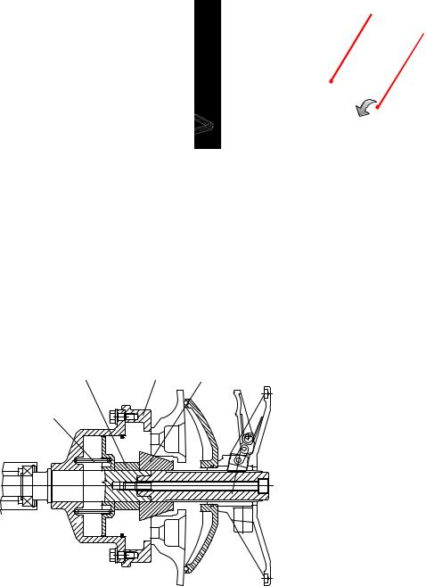
-Correct head disassembly (also see exploded drawings): the weight-holder head is anchored to the bed on the front side with snap-fitting clips; on the rear side, it is secured by a safety screw accessed by removing the control panel.
1.1.1 - STANDARD SAFETY DEVICES
-Stop push button for stopping the wheel under emergency conditions.
-The wheel guard is not compulsory since the balancing speed is less than 100 min-1.
1.2 - FIELD OF APPLICATION
The machine is designed for balancing wheels of car, light commercial vehicles or motorcycle, weighing less than 65 Kg. It can be operated in the temperature range of 0° to + 45° C.
The following functions are provided: Double operator; ALU-S; SPLIT; Unbalance optimization; Self diagnostics; Self-calibration
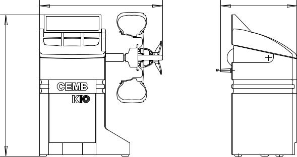
1.3 - OVERALL DIMENSIONS
Fig. 1
860
990
533 |
I 0215 GB - 3

1.4 - SPECIFICATION
Weight (excluding adapter) |
~ 80Kg. |
Single-phase power supply |
115 / 230 V 50/60 Hz |
Protection class |
IP 54 |
Max power consumption |
800 W |
Balancing speed |
< 100 min-1 |
Cycle time for average wheel (14 kg) |
6-8 seconds |
Max.resolution of measurement |
1 gram |
Position resolution |
± 1.4 ° |
Average noise |
< 70dB (A) |
Rim-machine distance |
0 - 265 mm |
Rim width setting range |
1.5” ÷ 20” or 40 ÷ 510 mm |
Diameter setting range |
10” ÷ 26” or 265 ÷ 665 mm |
2 - HANDLING AND HOISTING
Fig. 2 |
Fig. 2a |
NOTE: DO NOT HOIST THE MACHINE USING DIFFERENT GRIPS (See “Correct head disassembly” - paragraph:
3 - COMMISSIONING
3.1 - ANCHORING
The machine can operate on any flat non resilient floor.
Make sure that the machine rests solely on the three support points provided (fig.2a).
3.2 - ELECTRICAL CONNECTION
The machine is supplied with a single phase mains cable plus earth (ground).
The supply voltage (and mains frequency) is given on the machine nameplate. It cannot be changed. Connection to the mains should always be made by expert personnel.
The machine should not be started up without proper earthing.
Connection to the mains should be through a slow acting safety switch rated at 3 A (230V) or 8 A (115V). See enclosed layout.
I 0215 GB - 4
3.3 - ADAPTER MOUNTING |
Fig. 3 |
The wheel balancing machine is supplied complete with cone adapter for fastening wheels with central bore. Other optional adapters can be mounted:
a) Remove threaded end piece A after backing off screw B. b) Mount the new adapter (see enclosed brochures).
Note: CAREFULLY CLEAN THE COUPLING SURFACES
BEFORE PERFORMING ANY OPERATION.
A
B
3.4 - WHEEL GUARD ASSEMBLY AND ADJUSTMENT (OPTIONAL)
a) Fasten the components to the base as illustrated in the specific exploded drawing.
b) The position of the wheel guard when closed can be adjusted with relative screw accessible at the back. Correct position is the one which keeps the tube exactly horizontal with the wheel guard closed.
c) Check that the microswitch is held down when the guard is closed.
Note: Do not lean on the guard during the wheel balancing cycle.
3.5 - SPACER WD
When balancing very wide wheels (9”), there is not enough space to turn the distance gauge. To withdraw the wheel from the machine side, fit spacer WD on the adapter body and secure it with the standard issue nuts. When centring the wheel with the cone on the inside, fit the DC spacer to obtain spring thrust.
DC |
WD |
Cone |
Fig.3a |
|
|
Spring |
|
|
4 - CONTROLS AND COMPONENTS
4.1 - MANUAL RIM DISTANCE GAUGE
This gauge serves for manual measurement of the distance of the point of application of the counterweight from the machine.
I 0215 GB - 5

4.2 - CONTROL PANEL AND DISPLAY
Fig. 4
6
13
1 |
|
2 |
|
8 9 10 11 12
14
3 4 7
15 |
16 |
17 |
5
1-2 Digital readouts, AMOUNT OF UNBALANCE, inside/outside
3-4 Digital readouts, POSITION OF UNBALANCE, inside/outside
5 Indicators, correction mode selected
6Indicators, selection made
7 Push button, unbalance reading < 5 g (25 oz)
8Push button, operator selection
9Correction mode selection pushbutton
10Push button, SPLIT (unbalance resolution)
11Push button, FUNCTIONS MENU
12Menu selection confirmation pushbutton
13Push button, cycle start
14Push button, emergency/home
15Push buttons, manual DISTANCE setting
16Push buttons, manual DIAMETER setting
17Push buttons, manual WIDTH setting
Note: - Press buttons only with your fingers. Never use the counterweight pincers or other pointed objects.
-When the beep signal is enabled (see FUNCTION MENU MANAGEMENT), pressing of any push button is accompanied by a “Beep”.
I 0215 GB - 6
 Loading...