


Instructions for use 
 I
I
INDEX |
page |
1 |
- GENERAL ..................................................................................................................................................................... |
3 |
|
|
1.1 |
- GENERAL SAFETY REGULATIONS .............................................................................................................. |
3 |
|
|
1.1.1 - STANDARD SAFETY DEVICES ......................................................................................................... |
3 |
|
1.2 |
- FIELD OF APPLICATION ............................................................................................................................... |
3 |
|
1.3 |
- OVERALL DIMENSIONS ............................................................................................................................... |
3 |
|
1.4- TECHNICAL DATA ............................................................................................................................................ |
4 |
|
2 |
- TRANSPORT, HOISTING ........................................................................................................................................... |
4 |
|
3 |
- START-UP ................................................................................................................................................................... |
5 |
|
|
3.1 |
- ANCHORING .................................................................................................................................................... |
5 |
|
3.2 |
- ELECTRICAL CONNECTION ........................................................................................................................ |
5 |
|
3.3 |
- ADAPTER MOUNTING .................................................................................................................................. |
5 |
|
3.4 |
- FITTING AND ADJUSTING THE GUARD ....................................................................................................... |
5 |
|
3.5 |
- SPACER WD ...................................................................................................................................................... |
5 |
4 |
- CONTROLS AND COMPONENTS ............................................................................................................................. |
6 |
|
|
4.1 - MANUAL DISTANCE MEASUREMENT GAUGE ( C 61 ) ................................................................................ |
6 |
|
|
4.2 |
- AUTOMATIC DISTANCE AND DIAMETER GAUGE ( C 61 Z ) .......................................................................... |
6 |
|
4.3 |
- AUTOMATIC WHEEL POSITIONING ............................................................................................................... |
6 |
|
4.4 |
- CONTROL PANEL AND DISPLAY .................................................................................................................. |
6 |
|
|
4.4.1 OPERATION FUNCTIONS MENU ........................................................................................................... |
7 |
5 |
- INDICATION AND USE OF THE WHEEL BALANCER ............................................................................................. |
8 |
|
|
5.1 |
- DOUBLE OPERATOR PROGRAM ................................................................................................................ |
8 |
|
5.2 |
- PRESETTING OF WHEEL DIMENSIONS ..................................................................................................... |
8 |
|
|
5.2.1 - AUTOMATIC PRESETTING ( C 61 Z ) ............................................................................................... |
8 |
|
|
5.2.2 - MANUAL PRESETTING ( C 61 ) ...................................................................................................... |
9 |
|
|
5.2.3 - SETTING WITH GAUGE EXTENSION ( OPTIONAL C 61 ) ........................................................... |
10 |
|
5.3 |
- RECALCULATION OF THE UNBALANCE ..................................................................................................... |
11 |
|
5.4 |
- MEASUREMENT RESULT ............................................................................................................................ |
11 |
|
|
5.4.1 - INDICATION OF EXACT CORRECTION WEIGHT POSITION ....................................................... |
12 |
|
|
5.4.2 - SPILT FUNCTION .............................................................................................................................. |
13 |
|
|
5.4.3 - UNBALANCE OPTIMIZATION .......................................................................................................... |
14 |
|
|
5.4.4 - ALU AND STATIC MODES ................................................................................................................ |
15 |
|
|
5.4.5 - AUTOMATIC MINIMIZATION OF STATIC UNBALANCE ................................................................... |
15 |
6 |
- SET UP ...................................................................................................................................................................... |
16 |
|
|
6.1 |
- SELF-DIAGNOSTICS ...................................................................................................................................... |
16 |
|
6.2 |
- SELF-CALIBRATION ..................................................................................................................................... |
17 |
|
6.3 |
- AUTOMATIC GAUGES .................................................................................................................................... |
18 |
|
|
6.3.1 - DISTANCE GAUGE ........................................................................................................................... |
18 |
|
|
6.3.2 - DIAMETER GAUGE .......................................................................................................................... |
18 |
7 |
- ERRORS ................................................................................................................................................................... |
19 |
|
|
7.1 |
- INCONSISTENT UNBALANCE READINGS .................................................................................................. |
19 |
8 |
- ROUTINE MAINTENANCE ......................................................................................................................................... |
20 |
|
|
8.1 |
- REPLACING FUSES ...................................................................................................................................... |
20 |
9 |
- RECOMMENDED SPARE PARTS LIST ..................................................................................................................... |
20 |
|
I 0184 GB - 1
I 0184 GB- 2

1- GENERAL
1.1 - GENERAL SAFETY REGULATIONS
-The wheel balancing machine should only be used by duly authorized and trained personnel.
-The wheel balancing machine should not be used for purposes other than those described in the instruction manual.
-Under no way should the wheel balancing machine be modified except for those modifications made explicitly by the manufacturer.
-Never remove the safety devices. Any work on the machine should only be carried out by specialist personnel.
-Avoid using strong jets of compressed air for cleaning.
-Use alcohol to clean plastic panels or shelves (AVOID LIQUIDS CONTAINING SOLVENTS).
-Before starting the wheel balancing cycle, make sure that the wheel is securely locked on the adapter.
-The machine operator should avoid wearing clothes with flapping edges. Make sure that unauthorized personnel do not approach the machine during the work cycle.
-Avoid placing objects inside the base as they could impair the correct operation of the machine.
1.1.1 - STANDARD SAFETY DEVICES
-Stop push button for stopping the wheel under emergency conditions.
-Highly shock resistant plastic guard whose shape and size are designed to avoid the danger of counterweights spinning off in any direction except downwards.
-A microswitch will not let the machine start up if the guard is not down and stops the motor whenever the guard is raised.
1.2 - FIELD OF APPLICATION
The machine is designed for balancing wheels of car, light commercial vehicles or motorcycle, weighing less than 65 Kg. It can be operated in the temperature range of 0° to + 45° C.
The following functions are provided: Double operator; ALU-S ( automatic only with C61Z ); SPLIT; Unbalance optimization; Self diagnostics; Self-calibration
1.3 - OVERALL DIMENSIONS
Fig. 1 (standard guard)
1424 |
1233 |
1660
I 0184 GB - 3

Fig. 1a (42” guard)
1636 |
1283 |
1950 |
|
687 |
|
1.4 - SPECIFICATION
Weight with guard (excluding adapter) Single-phase power supply Protection class
Max. power consumption Balancing speed
Cycle time for average wheel (14 Kg) Max. resolution of measurement Position resolution
Average noise Rim-machine distance Rim width setting range Diameter setting range
Total wheel diameter inside guard Total wheel width inside guard
~ 92Kg.
115 / 230 V 50/60 Hz IP 54
1100 W
180 min-1
6 seconds
1 gram
± 1.4 °
< 70dB (A) 0 - 265 mm
1.5” ÷ 20” or 40 ÷ 510 mm 10” ÷ 24” or 265 ÷ 615 mm
870 mm standard - 1067 mm (42”)
430 mm standard - 500 mm (42”)
2 - TRANSPORT, HOISTING
Fig. 2 |
Fig. 2a |
NOTE: NEVER USE OTHER POINTS TO HOIST THE MACHINE
I 0184 GB- 4

3 - START-UP
3.1 - ANCHORING
The machine can operate on any fl at non resilient fl oor.
Make sure that the machine rests solely on the three support points provided (fi g.2a).
It is advisable to secure the system to the ground using the specific feet (see fig. 2a) in the event of continual use with wheels weighing over 35 Kg.
3.2 - ELECTRICAL CONNECTION
The machine is supplied with a single phase mains cable plus earth (ground).
The supply voltage (and mains frequency) is given on the machine nameplate. It cannot be changed. Connection to the mains should always be made by expert personnel.
The machine should not be started up without proper earthing.
Connection to the mains should be through a slow acting safety switch rated at 4 A (230V) or 10 A (115V). See enclosed wiring diagram.
3.3 - ADAPTER MOUNTING
The wheel balancer is supplied complete with cone type adapter for fastening wheels with central bore. Other optional adapters can be mounted:
a)Remove threaded end piece A after backing off screw B.
b)Mount the new adapter (see enclosed brochures).
NOTE: CAREFULLY CLEAN THE COUPLING SURFACES
BEFORE PERFORMING ANY OPERATION.
A
B
3.4 - FITTING AND ADJUSTING THE GUARD
a)Insert the wheel guard tube in its seat.
b)Fit the mounting bolts and tighten them securely.
The guard closed position can be adjusted by means of relative screw accessible from the rear of the machine. Adjust the angular position of microswitch control.
Correct position is the one which keeps the tube exactly horizontal with the wheel guard closed (for the standard guard (fig. 1). For the 42” guard, see guard and dimensions in fig. 1A.
3.5 - SPACER WD
When balancing very wide wheels (9”), there is not enough space to turn the distance gauge. To withdraw the wheel from the machine side, fi t spacer WD on the adapter body and secure it with the standard issue nuts. When centring the wheel with the cone on the inside, fi t the DC spacer to obtain spring thrust.
Fig.3a
DC |
WD |
Cone |
Spring
I 0184 GB - 5
4 - CONTROLS AND COMPONENTS
4.1 - MANUAL DISTANCE MEASUREMENT GAUGE ( C 61 )
This gauge serves for manual measurement of the distance of the point of application of the counterweight
FI from the machine.
4.2 - AUTOMATIC DISTANCE AND DIAMETER GAUGE ( C 61Z )
This gauge allow measuring distance of the rim from the machine and the diameter at the point of application of the counterweight. The same gauge can be used to position correctly the counterweights inside the rim, using the specifi c function (see EXACT CORRECTION POSITION INDICATION ), that enables display of the position used for measurement (for calibration, see AUTOMATIC PRESETTING ( C61 Z ) ).
The gauge may only be used with the weight-holder pincer fitted.
4.3 - AUTOMATIC WHEEL POSITIONING
At the end of the run, the wheel is positioned in relation to external or static out-of-balance (when selected).
Positioning is disabled automatically for wheels less than 13” in diameter. Accuracy is approx. ± 20 degrees for wheels weighing up to 25 Kg.
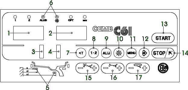
4.4 - CONTROL PANEL AND DISPLAY
Fig. 4
1-2 |
Digital readouts, AMOUNT OF UNBALANCE, |
12 |
Push button, menu selection confi rmation |
|
inside/outside |
13 |
Push button, cycle start |
3-4 |
Digital readouts, POSITION OF UNBALANCE, |
14 |
Push button, emergency/home |
|
inside/outside |
15 |
Push buttons, manual DISTANCE setting |
5 |
Indicators, correction mode selected |
16 |
Push buttons, manual DIAMETER setting |
6 |
Indicators, selection made |
17 |
Push buttons, manual WIDTH setting |
7Push button, unbalance reading < 5 g (25 oz)
8Push button, operator selection
9Push button, selection of mode of correction
10Push button, SPLIT (unbalance resolution)
11Push button, FUNCTIONS MENU
Note: - Press buttons only with your fi ngers. Never use the counterweight pincers or other pointed objects.
-When the beep signal is enabled (see OPERATION FUNCTIONS MENU) pressing of any push button is accompanied by a “Beep”.
I 0184 GB- 6
 Loading...