


Instructions for use |
|
I |
TABLE OF CONTENTS |
Page |
||
1 |
- GENERAL ..................................................................................................................................................................... |
3 |
|
|
1.1 |
- GENERAL SAFETY REGULATIONS ................................................................................................................ |
3 |
|
|
1.1.1 - STANDARD SAFETY DEVICES .......................................................................................................... |
3 |
|
1.2 |
- FIELD OF APPLICATION ................................................................................................................................. |
3 |
|
1.3 |
- OVERALL DIMENSIONS .................................................................................................................................. |
3 |
|
1.4- TECHNICAL DATA .............................................................................................................................................. |
4 |
|
2 |
- HANDLING AND LIFTING ........................................................................................................................................... |
4 |
|
3 |
- STARTUP ..................................................................................................................................................................... |
4 |
|
|
3.1 |
- ANCHORING...................................................................................................................................................... |
4 |
|
3.2 |
- ELECTRICAL CONNECTION ........................................................................................................................... |
4 |
|
3.3 |
- FLANGE MOUNTING......................................................................................................................................... |
5 |
|
3.4 |
- WHEEL GUARD ASSEMBLY AND ADJUSTMENT (OPTIONAL) ..................................................................... |
5 |
|
3.5 |
- WD SPACER ..................................................................................................................................................... |
5 |
4 |
- CONTROLS AND COMPONENTS .............................................................................................................................. |
5 |
|
|
4.1 - MANUAL DISTANCE MEASUREMENT GAUGE ............................................................................................. |
5 |
|
|
4.2 |
- KEYBOARD AND DISPLAY ............................................................................................................................... |
6 |
|
|
4.2.1 FUNCTION MENU MANAGEMENT ........................................................................................................ |
7 |
5 |
- INSTRUCTIONS FOR USE OF THE WHEEL BALANCER ........................................................................................ |
8 |
|
|
5.1 |
- SETTING THE WHEEL DIMENSIONS ............................................................................................................ |
8 |
|
5.2 |
- MEASUREMENT RESULT ............................................................................................................................. |
11 |
|
5.3 - RECALCULATION OF THE UNBALANCE VALUES ...................................................................................... |
11 |
|
|
5.4 - SPLIT FUNCTION (hidden weight) .................................................................................................................. |
12 |
|
|
5.5 - OUT OF BALANCE OPTIMIZATION................................................................................................................ |
13 |
|
|
5.6 - AUTOMATIC MINIMISATION OF STATIC UNBALANCE ............................................................................... |
14 |
|
6 |
- SET-UP ...................................................................................................................................................................... |
15 |
|
|
6.1 |
- AUTODIAGNOSTICS....................................................................................................................................... |
15 |
|
6.2 |
- AUTOCALIBRATION........................................................................................................................................ |
15 |
7 |
- ERRORS .................................................................................................................................................................... |
16 |
|
|
7.1 |
- INCONSISTENT UNBALANCE READINGS .................................................................................................. |
17 |
8 |
- ROUTINE MAINTENANCE ........................................................................................................................................ |
17 |
|
|
8.1 |
- REPLACING THE PROTECTION FUSES ...................................................................................................... |
17 |
9 |
- LIST OF RECOMMENDED SPARE PARTS ............................................................................................................... |
17 |
|
I 0369 GB - 1
I 0369 GB - 2

1 - General
1.1 - General safety regulations
-The wheel balancer may only be used by duly authorized and trained personnel.
-The wheel balancer must not be used for purposes other than those described in the instruction manual.
-The wheel balancer must not be modifi ed in any way except for those modifi cations made
explicitly by the manufacturer.
-Do not remove the safety devices. Any work on the machine must be carried out by specialised personnel only.
-Avoid using strong jets of compressed air for cleaning.
-Use alcohol to clean plastic panels or shelves (AVOID LIQUIDS CONTAINING SOLVENTS).
-Before starting the wheel balancing cycle, make sure that the wheel is securely locked on the flange.
-The machine operator must not wear clothes with fl apping parts. Do not allow unauthorized personnel to approach the wheel balancer when the cycle is running.
-Avoid placing objects in the base which could impair the correct operation of the wheel balancing machine.
-Before disassembling the weight shelf, remove the guard (see specific instructions)
1.1.1- Standard safety devices
-Stop push button for stopping the wheel under emergency conditions.
-The wheel guard is not compulsory since the balancing speed is less than 100 min-1.
1.2 - Field of application
The machine is designed for balancing wheels of cars, light commercial vehicles or motorcycles weighing less than 75 kg. It can be operated in a temperature range of 0° to + 45° C.
The following functions are provided: ALU-S; SPLIT; Unbalance optimisation; Autodiagnostics; Autocalibration.
1.3 - Overall dimensions (standard guard)
1
1225 |
940 |
1345 |
|
620 |
|
I 0369 GB - 3
1.4 - Technical data
Single-phase power supply |
115 / 230 V - 50/60 Hz |
Protection class |
IP 54 |
Max. power absorbed |
0,8 Kw |
Balancing speed |
< 100 min-1 |
Cycle time for average wheel (14 kg) |
6-8 seconds |
Max. resolution of measurement |
1 gram |
Position resolution |
± 1.4 ° |
Average noise |
< 70dB (A) |
Rim-machine distance |
0 - 252 mm |
Rim width setting range |
1.5” - 20” or 40 - 510 mm |
Diameter setting range |
10” - 26” or 265 - 665 mm |
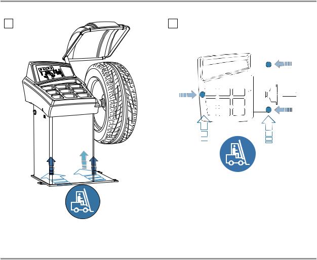
2 - Handling and lifting |
|
2 |
2a |
Note: DO NOT LIFT THE WHEEL BALANCER USING OTHER GRIPS
3 - Startup
3.1 - Anchoring
The machine can operate on any fl at non resilient fl oor.
Make sure that the machine rests solely on the three support points provided (Fig.2a).
It is advisable to secure the system to the ground using the specific feet (Fig. 2a). if the machine is continually used with wheels weighing over 35 kg.
3.2 - Electrical connection
The machine is supplied with a single-phase mains cable plus earth (ground).
The power supply voltage (and mains frequency) is indicated on the machine identification plate and cannot be changed.
Connection to the mains must always be made by expert personnel. The machine must not be set up without proper earthing.
Connection to the mains should be through a slow acting safety switch rated at 3 A (230V) or 8 A(115 V). See enclosed diagram.
I 0369 GB - 4
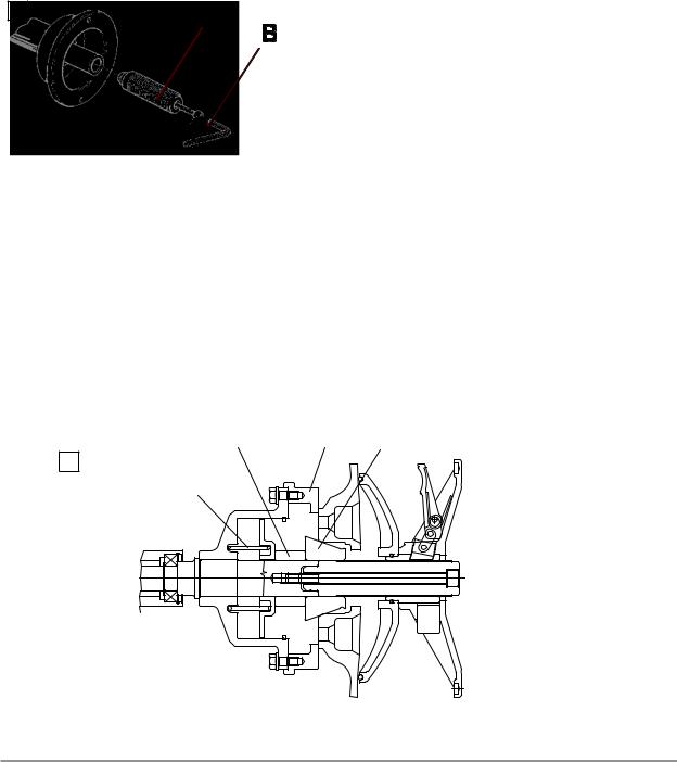
3.3 - Flange mounting
3 |
The wheel balancer is supplied complete with cone |
|
flanges |
|
for fixing wheels with a central hole. Other optional |
|
flanges can be mounted: |
|
a) Remove the threaded end-piece A after unscrewing |
|
the screw B. |
|
b) Mount the new flange (see attached sheets). |
|
Note: CAREFULLY CLEAN THE COUPLING |
|
SURFACES BEFORE PERFORMINGANY |
|
OPERATION. |
3.4 - Wheel guard assembly and adjustment (optional)
Fix the components to the base as described in the attachment “WHEEL GUARD ASSEMBLY SEQUENCE” at the end of the manual.
N.B.: Do not lean on the guard during the wheel balancing cycle.
3.5 - WD spacer (option)
When balancing very wide wheels (9”), there is not enough space to turn the distance gauge. To move the wheel away from the machine side, fit the WD spacer on the flange body and secure it with the standard issue nuts. When centring the wheel with cone from the inside, mount the DC spacer to obtain spring thrust.
|
|
|
3a
4 - Controls and components
4.1 - Manual distance measurement gauge
This gauge serves to manually measure the distance between the point of application of the counterweight and the machine.
I 0369 GB - 5

4.2 - Keyboard and display
|
1 |
2 |
4 |
8
|
|
|
|
|
10 |
|
|
|
|
|
15 |
12 |
|
|
|
|
|
|
|
|
|
|
|
|
|
|
|
||
|
|
|
9 |
|
|
|
|
|
11 |
|
|
16 |
18 |
13 |
|
|
|
|
|
|
|
|
|
|
|
19 |
14 |
||
|
|
|
|
|
|
|
|
|
|
|
|
|
||
|
|
|
|
|
|
|
|
|
|
|
|
|
|
|
|
|
|
|
|
|
|
|
|
|
|
|
|
17 |
|
|
|
|
|
|
|
|
|
|
|
|
|
|
|
|
|
|
|
|
|
|
|
|
|
|
|
|
|
|
|
|
|
|
|
|
|
|
|
|
|
|
|
|
|
|
|
|
|
|
|
|
|
|
|
|
|
|
|
|
|
|
3 |
5 |
6 |
7 |
4 |
|
|
|
|
|||||
1-2 |
Digital readouts, AMOUNT OF UNBALANCE, inside/ |
11 |
Manual DIAMETER setting button |
|||||||||||
|
outside |
|
|
|
|
|
|
|
|
12 |
Push button, FUNCTION MENU |
|||
3-4 |
Digital readouts, POSITION OF UNBALANCE, |
13 |
Balancing cycle stop button |
|||||||||||
|
inside/outside |
|
|
|
|
|
|
|
|
14 |
Balancing cycle start button |
|||
5 |
Inside correction mode selection button |
|
|
|
|
15 |
Unbalance optimization push button |
|||||||
6 |
Indicators, correction mode selected |
|
|
|
|
16 |
Push button, SPLIT |
(unbalance resolution) |
||||||
7 |
Outside correction mode selection button |
|
|
|
|
17 |
HOME push button |
|
||||||
8 |
Special function indicators |
|
|
|
|
|
|
18 |
MENU selection confirmation pushbutton |
|||||
9 |
Manual DISTANCE setting button |
|
|
|
|
19 |
Push button, unbalance reading < 5 g (.25 oz) |
|||||||
10 |
Manual WIDTH setting button |
|
|
|
|
|
|
|
|
|
|
|||
Note: Press buttons only with your fingers. Do not use the counterweight grippers or other pointed objects.
I 0369 GB - 6
 Loading...