


CONTENTS |
CAUTION! |
3 |
|
|
|||
|
GENERAL WARNINGS |
3 |
|
|
PRECAUTIONS AND INSTRUCTIONS FOR SAFETY, USE AND MAINTENANCE |
3 |
|
|
|
|
|
|
TECHNICAL DATA |
5 |
|
|
COMPONENTS |
5 |
|
|
MACHINE DESCRIPTION |
5 |
|
|
|
|
|
|
|
|
|
|
1 - MACHINE USE |
8 |
|
|
|
|
|
|
1.1 |
- TURNING ON AND OFF |
8 |
|
1.2 |
- (RADIO MODELS) BATTERY AND COMMUNICATION STATUS |
8 |
|
|
|
|
|
1.3 |
- (RADIO MODELS) RECHARGING THE BATTERIES |
9 |
|
2 - PROGRAM FLOW |
10 |
|
|
|
|
|
|
2.1 |
- HOW TO INTERACT WITH THE PROGRAM |
11 |
|
|
|
|
|
3 - PREPARING FOR MEASUREMENT |
12 |
|
|
|
|
|
|
3.1 |
- HOME PAGE |
12 |
|
|
|
|
|
3.2 |
- SETTINGS |
14 |
|
3.3 |
- CUSTOMER DATABANK |
16 |
|
|
|
|
|
4 - VEHICLE SELECTION |
17 |
|
|
4.1 |
- SELECTING A VEHICLE MAKE |
17 |
|
|
|
|
|
4.2 |
- CUSTOMER INFORMATIONS |
17 |
|
4.3 |
- SELECTING THE VEHICLE MODEL |
18 |
|
|
|
|
|
5 - VEHICLE SPECIFICATIONS |
19 |
|
|
|
|
|
|
5.1 |
- ADJUSTMENT HELP IMAGES |
20 |
|
5.2 |
- RIDE HEIGHT |
21 |
|
|
|
|
|
5.3 |
- LOADS |
22 |
|
5.4 |
- VEHICLE CUSTOMISATION |
22 |
|
5.5 |
- (TRUCK ONLY) AXLE CONFIGURATION |
24 |
|
|
|
|
|
6 - RUNOUT |
26 |
|
|
6.1 |
- HOW TO EXECUTE RUNOUT |
28 |
|
|
|
|
|
6.2 |
- 180° OR 90° RUNOUT ON THE GROUND |
29 |
|
6.3 |
- 180° RUNOUT LIFTED |
31 |
|
|
|
|
|
6.4 |
- 3X90° RUNOUT LIFTED |
32 |
|
7 - STEERING |
33 |
|
|
|
|
|
|
7.1 |
- FAST STEERING |
34 |
|
7.2 |
- 10° OR 20° STEERING |
34 |
|
|
|
|
|
8 - DIAGNOSTICS |
35 |
|
|
9 - ADJUSTMENT |
36 |
|
|
|
|
|
|
9.1 |
- ADJUSTMENT PROCEDURES |
37 |
|
9.2 |
- (CAR) ADJUSTING A REAR AXLE |
37 |
|
9.3 |
- ADJUSTING A FRONT AXLE |
38 |
|
9.4 |
- (TRUCK) ADJUSTING A REAR AXLE |
41 |
|
9.5 |
- (TRUCK) ADJUST THE PARALLELISM BETWEEN THE TWO FRONT STEERING AXLES |
42 |
|
9.6 |
- (CAR, VAS PROCEDURE) ADJUSTING THE FRONT TOE-IN WITH THE VEHICLE RESTING ON A |
43 |
|
SUPPORT (TOE-IN CURVE) |
|
|
|
9.7 |
- ADJUSTING WITH THE WHEELS RAISED OR STEERED (FREEZING) |
44 |
|
9.8 |
- ADJUSTMENT IN CASE OF INTERRUPTION OF THE INFRARED RAYS |
45 |
|
|
|
|
|
10 - SUMMARY |
46 |
|
|
10.1 - VEHICLE DIMENSIONS |
47 |
|
|
|
|
|
|
10.2 - MAXIMUM STEERING |
47 |
|
|
11 - WHEEL ALIGNMENT AND MEASURING HEAD LEVELLING |
48 |
|
|
|
|
|
I 0645 GB  1
1

12 |
- SPOILER |
49 |
|
13 |
- MAINTENANCE |
51 |
|
|
|
|
|
13.1 |
- CLEANING |
51 |
|
13.2 |
- HOW TO UPDATE THE DATABANK AND THE SOFTWARE |
51 |
|
13.3 |
- HOW TO ACTIVATE THE DATABANK AND THE SOFTWARE |
53 |
|
14 |
- TROUBLESHOOTING |
55 |
|
14.1 |
- MALFUNCTIONS |
55 |
|
14.2 |
- ALIGNMENT PROBLEMS |
57 |
|
15 |
- |
STORING AND SCRAPPING |
59 |
15.1 |
- STORING |
59 |
|
|
|
|
|
15.2 |
- SCRAPPING |
59 |
|
16 |
- TESTING THE MEASURING HEADS BY FITTING THEM ON THE VEHICLE |
60 |
|
|
|
|
|
16.1 |
- MEASUREMENT I – TOE-IN AND CAMBER IN DRIVING DIRECTION |
60 |
|
16.2 |
- MEASUREMENT II - TOE-IN AND CAMBER IN REVERSE DRIVING DIRECTION |
60 |
|
|
|
|
|
16.3 |
- EVALUATION OF THE VALUES MEASURED DURING THE MEASURING HEAD TEST |
60 |
|
I 0645 GB  2
2

CAUTION!
THIS MANUAL FORMS AN INTEGRAL PART OF THE PRODUCT AND ITS PURPOSE IS TO PROVIDE USERS WITH THE NECESSARY OPERATING INSTRUCTIONS FOR THE WHEEL ALIGNER. CAREFULLY READ THE MANUAL BEFORE USING THE WHEEL ALIGNER AND EACH TIME YOU NEED TO OPERATE ON THE MACHINE. KEEP IT IN AN ACCESSIBLE PLACE FOR THE ENTIRE OPERATING LIFETIME OF THE MACHINE. ANY DAMAGE DERIVING FROM FAILURE TO OBSERVE THE INSTRUCTIONS CONTAINED IN THIS MANUAL AS WELL AS FROM IMPROPER USE OF THE MACHINE RELIEVES THE MANUFACTURER OF ALL RESPONSIBILITY.
General warnings
The manual refers to the essential requirements set out in the directives, standards and provisions pertaining to use of the machine summarising the most significant points.
In addition to the service instructions, the general rules of law and the binding rules regarding the prevention of accidents and protection of the environment must be observed.
For all the work to be carried out with or on the machine, the following provisions must be complied with as well as the general safety regulations following the instructions.
The user must ensure that the machine is always and only used in perfect condition taking into account the essential safety requirements and the applicable regulations.
The machine must immediately be put out of service if any defects or malfunctioning is found. Only trustworthy persons may work with the machine; the user is responsible for ensuring that the persons assigned to the job are suitably qualified and trained.
For any doubts about use and maintenance of the machine, consult this manual; if necessary, contact the authorised technical service centres.
Precautions and instructions for safety, use and maintenance
The data plate bearing the voltage and frequency data is affixed on the rear of the machine.
NEVER CONNECT THE MACHINE TO A VOLTAGE OR FREQUENCY OTHER THAN THOSE INDICATED.
The machine is equipped with a 3-wire plug with incorporated earth to be inserted only in an earthed socket. If it is not possible to fit the plug in a socket of this kind, please consult an electrician.
Do not modify or improperly use the plug.
This machine is not equipped with a manual power cutting device. To cut the power, pull out the plug or turn off the main switch positioned upstream.
All the operations on live electrical parts must be performed after turning off the power switch on the electric cabinet.
Do not remove or make unrecognizable the danger warning plates, adhesive labels and markings on the machine and
make sure that they are always legible.
All the maintenance and inspection operations must exclusively be carried out by qualified persons. Mechanical and electrical repairs as well as setting operations may only be carried out by qualified persons.
Unauthorised persons must be prohibited from performing any work on the machines and equipment of the system.
In the event of significant faults that may compromise the safety and/or reliability of the machine, it must be stopped and in any case not started before the faults have been corrected.
It is prohibited to transform or make modifications to the electric system.
The user will be held responsible for any damages as a result of such modifications. In case of doubt, please contact the manufacturer before making any modifications.
Exclusively use original fuses with the specified capacity in ampere! In the event of electrical power supply faults, the machine must immediately be turned off.
Defective fuses may not be repaired or deactivated, but must be replaced with fuses of the same type.
Comply with the environmental protection regulations when disposing of waste substances or replaced parts.
I 0645 GB  3
3
I 0645 GB  4
4

MACHINE DESCRIPTION
The wheel aligner is a machine intended for measuring the characteristic angles of motor vehicles, in particular, the camber, toe-in and caster.
Technical data
Power supply and consumption
Measuring cabinet
Power supply: |
|
230 VAC single-phase 50/60 Hz |
|
|
|
110 VAC single-phase on request |
|
|
|
|
|
Max power absorbed: |
|
500 W |
|
|
|
|
|
Max current absorbed: |
|
2.17 A |
|
|
|
|
|
Measuring heads |
|
|
|
Internal power supply: |
|
7.2 V rechargeable batteries |
|
|
|
(Li-Ion) |
|
|
|
|
|
External power supply: |
|
12 V (via cable), optional for radio |
|
|
|
model |
|
|
|
|
|
Components |
|
1 |
|
|
|
Cabinet |
4 |
3 |
|
||
|
4 |
|
|
|
1.Display
2.Tool tray
3.Keyboard
4.Wheel clamp and measuring head holders
5.Measuring heads
6.Printer
5
5
6 |
2 |
The image is only an example of the parts.
The actual shapes of the cabinet, the display and the printer may differ
I 0645 GB 5

Measuring heads
The measuring heads are made up of CCD transducers to measure the horizontal angles and accelerometers to measure the vertical angles. In the cable version, both the power supply and data transmission is via cable. In the radio version, power is supplied by rechargeable batteries; when the batteries are flat, measurements can still be made by connecting the battery charge cables - supplied as option and not included in the standard equipment - to the measuring heads. Data transmission is via radio.
To turn on the measuring heads, connect the power cables or, only for the radio models, press any key on the keypad.
The measuring heads turn off automatically after about 15 minutes if no data is transmitted or the cabinet is off.
1. Keyboard
2. 3 LEDs for measuring head levelling
3. Connector for battery charge cable
4. Pin locking knob
1. Level indicator with red/green/red LED
Measuring head level
Measuring head off level
Measuring head off level
2. Power on/off
3. OK
4. Next page
5. Previous page
I 0645 GB  6
6
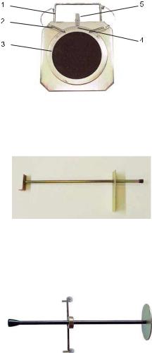
Turn plates
Plate diameter: 310 mm Capacity: 1000 kg each.
1. Handle
2. Off
3. Plate with non-slip disc
4. Goniometer
5. Reference dial
Brake pedal lock
This device is used to lock the brake pedal while preparing to make a measurement.
Steering lock
This device is used to hold the steering wheel in a fixed position; it is positioned before carrying out the vehicle adjustment operations.
I 0645 GB  7
7

1 - MACHINE USE
1.1 - Turning on and off
Locate the computer power switch on the rear of the cabinet.
To turn on the computer:
1.Set the power switch (1) to ON (I)
2.(Linux models) If the computer does not start automatically, press the Reset button (2) inside the cabinet.
3.(Windows models) Click on the Application icon on the desktop.
To turn off the computer:
1.(Windows models) Click on the home page to close the program.
2.(Windows models) Close Windows by clicking on Start / Turn off computer
3.Set the power switch (1) to OFF (O)
1.2 - (radio models) Battery and communication status
On some pages battery icons are displayed, which indicate the status of the batteries and the communication between the computer and the measuring heads.
FRONT LH |
|
|
|
FRONT RH |
|
|
|
|
|
REAR LH |
|
|
|
REAR RH |
|
|
|
|
|
The colour of the battery icons indicates the status of the radio connection and the battery charge:
•Light blue: battery recharging or almost fully charged
•Green: battery charged
•Yellow: battery low; estimated operating time 60 minutes
•Red: battery flat estimated operating time 30 minutes
•Grey: no communication
• Black: rear measuring head not used in the 2 measuring heads mode
I 0645 GB 8
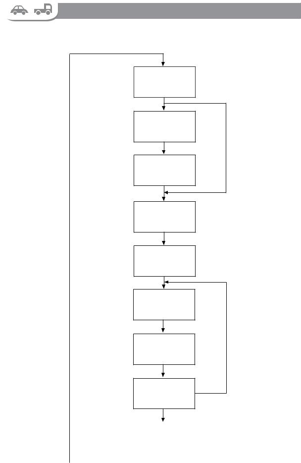
2 - PROGRAM FLOW
The following flow chart schematizes the typical program flow for a car or truck with only two axles. In case of trucks with more axles certain operations must be repeated.
Chapter 5
Chapter 6
Chapter 7
Paragraph 5.5
Chapter 8
Chapter 9
Chapter 10
Chapter 11
PREPARING FOR
MEASUREMENT
VEHICLE
SELECTION
SKIP VEHICLE
SELECTION
VEHICLE
SPECIFICATIONS
(TRUCK ONLY) AXLE SELECTION
RUNOUT
(CAR ONLY) STEERING
(TRUCK AND CAR) EXECUTE STEERING
DIAGNOSTICS
ADJUSTMENT
Chapter 12 |
SUMMARY |
|
|
|
|
|
|
|
I 0645 GB  10
10

2.1 - How to interact with the program
The operations indicated by the on-screen keys F1 ... F7 can be performed by clicking on or pressing  ...
...
 on the keyboard or pressing the arrow buttons of the measuring head keypad.
On the normal pages (image on the left)
... |
|
|
|
: the function of these keys varies from page to page |
or |
|
|
|
: goes back to the previous page |
|
||||
or |
|
|
|
: goes to the next page |
|
|
|
||
|
|
|
||
|
|
|
|
: Help |
|
|
|
|
: goes back to the home page |
In the menus (image on the right) |
||||
... |
|
|
|
: Select the desired function |
|
|
|
|
: Exits from the menu |
•To save time and avoid moving between the vehicle and the cabinet you can move between the pages using the measuring head keypad.
•To continue with the alignment procedure press  or
or 
I 0645 GB  11
11
3 - PREPARING FOR MEASUREMENT
3.1 - Home page
The home page appears at the beginning of each alignment procedure.
From this page you can select the car and truck alignment procedure, as well as the measuring mode with 2 or 4 measuring heads. You can also access the Settings or the Customer Databank pages.
The measuring mode with 2 measuring heads allows measuring and adjusting only the toe-in and camber of the front axle. The measuring mode with 4 measuring heads is faster because you do not have to fit the rear measuring heads.
It is recommended that only experts use the mode with 2 measuring heads as it is not guaranteed that the steering wheel stays straight.
Generally, when the home page is displayed, the preliminary operations on the vehicle are performed.
To prepare for measurement:
1.Position the vehicle on the turn plates
2.Mount the wheel clamp and the measuring heads on the vehicle wheels
3.Turn on the computer
4.Turn on the measuring heads
CAR PROCEDURE |
TRUCK PROCEDURE |
2
1
b |
|
|
a |
a |
|
|
b |
|
3 |
||||||||
3 |
||||||||
1.Mode with two measuring heads active
2.Battery icon
3.Sensor positioning when HYBRID mode is active:
a.Sensor type CAR
b.Sensor type TRUCK
: Switch between the car or the truck procedure
: Switch between the mode with 2 or 4 measuring heads
: Menu
 : Settings page
 : Customer Databank page
: Goes directly to measurement without selecting the vehicle
I 0645 GB - 12

If the databank activation window appears on the home page
the databank must be activated  see paragraph 13.2
Nevertheless, the databank can be used for a limited number of times without activating it. To do this, press  to close the activation window.
3.2 - Settings
I 0645 GB  13
13
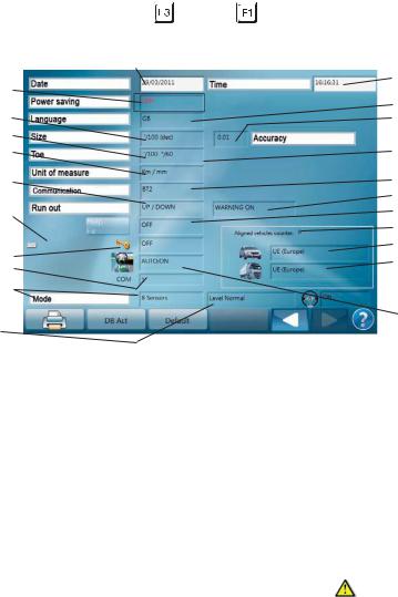
To access this page from the home page press |
and then |
. |
|
|
|
|||||
The following parameters can be set: |
|
|
|
|
|
|
||||
|
1 |
|
|
|
|
|
|
2 |
||
|
|
|
|
|
|
|
||||
|
3 |
|
|
|
|
|
|
|||
|
|
|
|
|
|
|
4 |
|||
|
5 |
|
|
|
|
|
|
|||
|
|
|
|
|
|
|
6 |
|||
|
7 |
|
|
|
|
|
|
|
|
|
|
9 |
|
|
|
|
|
|
8 |
||
|
11 |
|
|
|
|
|
|
10 |
||
|
|
|
|
|
|
|
|
12 |
||
|
14 |
|
|
|
|
|
|
13 |
||
|
|
|
|
|
|
|
16 |
|||
|
|
|
|
|
|
|
|
|||
|
15 |
|
|
|
|
|
|
17 |
||
|
|
|
|
|
|
|
18 |
|||
|
19 |
|
|
|
|
|
|
|||
|
|
|
|
|
|
|
|
|
||
|
20 |
|
|
|
|
|
|
|
22 |
|
|
|
|
|
|
|
|
|
|||
|
21 |
|
|
|
|
|
23 |
|||
|
|
|
|
|
|
|
|
|||
1. |
Date |
|
|
|
|
|
|
|||
2. |
Time |
|
13.Help texts: |
|
|
|||||
3. |
Time of inactivity after which the measuring |
|
• Fx: displays on the screen buttons the related |
|||||||
|
heads go into standby to reduce battery con- |
|
|
F1,...,F7 keyboard button. |
||||||
|
sumption (infrared LEDs off). The screen saver |
|
• Help: displays on the screen buttons their |
|||||||
|
is activated. To wake up the measuring heads, |
|
|
name |
|
|
||||
|
press any key on the keyboard. (option 'OFF' = it |
|
|
|
||||||
|
• ALL: displays the previous and pages titles |
|||||||||
|
does not occur) |
|
||||||||
4. |
Language |
|
14.Keyboard language |
|
|
|||||
5. |
Format of the fractions of an angle |
|
15.Settings page password ('ON' = password required |
|||||||
|
• '/100 (dec) = hundredths of a degree (centesi- |
to access the Settings page) |
||||||||
|
16.Number of alignments executed |
|||||||||
|
mal degrees) |
|
||||||||
|
• °/60 (min) = sixtieth of a degree (sexagesimal |
17.Car database active |
|
|
||||||
|
degrees) |
|
18.Truck database active |
|
|
|||||
6. Angle resolution shown on the display (the actual |
|
|
||||||||
19.COM port setting |
do not change (reserved |
|||||||||
|
resolution of the instrument does not change) |
|
||||||||
|
|
for technical service). |
||||||||
7. |
Toe-in format and resolution |
|
||||||||
|
20.In IBRIDA or HYBRID mode (*): measurements |
|||||||||
|
• '/100 °/60 = degrees, resolution specified in |
|
made with all the sensors (8 sensors) or disabling |
|||||||
|
box 6 |
|
the rear toe-in sensors (6 sensors). This second |
|||||||
|
• mm = millimetres, resolution specified in box 8 |
setting is useful in order to be able to make a |
||||||||
|
measurement also if the rear toe-in radius is |
|||||||||
|
• inch (dec) = inches, resolution in tenths of an |
|
||||||||
|
|
interrupted. * The measurement execution mode |
||||||||
|
inch |
|
requires the use of 2 CAR sensors and 2 TRUCK |
|||||||
|
• inch (1/4) = inches, resolution in fourths of an |
sensors. |
|
|
||||||
|
21.For the truck procedure only: level sensor tole- |
|||||||||
|
inch |
|
||||||||
|
• inch (1/64) = inches, resolution in sixty-fourths |
rance. Select the 'Normal' setting to optimise |
||||||||
|
measurement accuracy. Use the 'Wide' setting |
|||||||||
|
of an inch |
|
||||||||
|
|
only if you have difficulty keeping the measuring |
||||||||
|
|
|
|
|
||||||
8. |
Toe-in resolution if expressed in millimetres or |
|
heads level, for example, when measuring with |
|||||||
|
inches |
|
the engine on |
|
|
|||||
9. |
Distance unit of measure |
|
22. Option to disable caster measurement: |
|||||||
10.Type of communication between the measuring |
|
|
ON: steering required |
|||||||
|
|
OFF: steering not required |
||||||||
|
heads and the computer ('Cable' = via cable) 'BT' |
|
||||||||
|
= Bluetooth; 'BT2' = Second generation Blueto- |
|
|
|
|
|
|
|||
|
oth) |
|
23.Automatic next page for the brake pedal lock |
|||||||
11.Type of runout permitted ('UP/DOWN' = both |
|
and steering lock positioning pages |
||||||||
|
lifted and on the ground; 'UP' = lifted only; |
|
AUTO ON: the next page is automatically displa- |
|||||||
'Bypass' = runout execution not required) |
yed after 15 seconds |
|
12.Enables checks on correct runout execution |
||
AUTO OFF: you need to press F6 to go to the |
||
|
||
|
next page |
I 0645 GB  14
14

: Print settings |
see below |
|
: Databank/software activation |
see paragraph 13.2 |
|
: Reset to factory settings
: Saves the settings and exits


 : Allow selecting and setting the various parameters
Print settings
1.(Linux models) Printer model
2.Colour in which out-of-tolerance values are printed  : measurements before and after adjustment red
  : measurements before and after adjustment black
  : only measurements after adjustment (black)
3.Printer header
4.Print footer
5.Print mode
1.Tabular
2.Graphic
6.Possibility of printing the logo displayed on the Home page


 : Allow selecting and setting the various parameters
: Saves the settings and exits
I 0645 GB  15
15

3.3 - Customer databank
To access this page from the home page press  then
then  . From this page you can search for and display the customer informations and the relative vehicles measurements stored previously. You can search the data by customer name, vehicle license plate, date or work order. You can also backup or restore all the user data (customer informations and relative vehicles measurements + customized vehicles).
SEARCH BOX 
|
SELECTED CUSTOMER / |
CUSTOMER LIST |
VEHICLE |
|
 Displays the list of customers/vehicles corresponding to what was entered in the search box
 Deletes the customer/vehicle selected
 Backup
  see below
 Restore
  see below
 Selects the search box or the customer list
 Select the desired customer
: Displays the customer measurements of the selected customer
To backup the user data:
1.Plug a USB memory into a free USB port.
•(Linux models) The port is found on the rear of the cabinet near the power button
•(Windows models with cabinet): the port is found on the computer inside the cabinet
2.Press  . The user data is copied to the USB memory
3.Copy the user data files from the USB memory to a safe location on another computer
To restore the user data:
1.Copy the user data files to a USB memory
2.Plug a USB memory into a free USB port
3.Press  . The user data is copied to the computer
You can also use this method to transfer the user data from one alignment machine to another.
Restoring the user data deletes any user data already on the computer.
I 0645 GB  16
16

4 - VEHICLE SELECTION
4.1 - Selecting a vehicle make
The Vehicle Selection page allows selecting a vehicle so that during adjustment you can compare the measurements with the manufacturer's specifications and display adjustment help images.
The vehicle is selected first by manufacturer and then by model. For faster selection of the model you can display only the models registered as of the year indicated.
You can also insert informations on a customer, which are saved in the customer databank together with the summary of the measurements so that they can be viewed and printed later.
|
|
: To enter informations customer |
... |
, |
: To select the desired make |
: Confirms the make of the vehicle selected
4.2 - Customer informations
Press  to insert customer informations
: Selects the next field
: Selects the previous field
: Saves the informations and exits
I 0645 GB  17
17
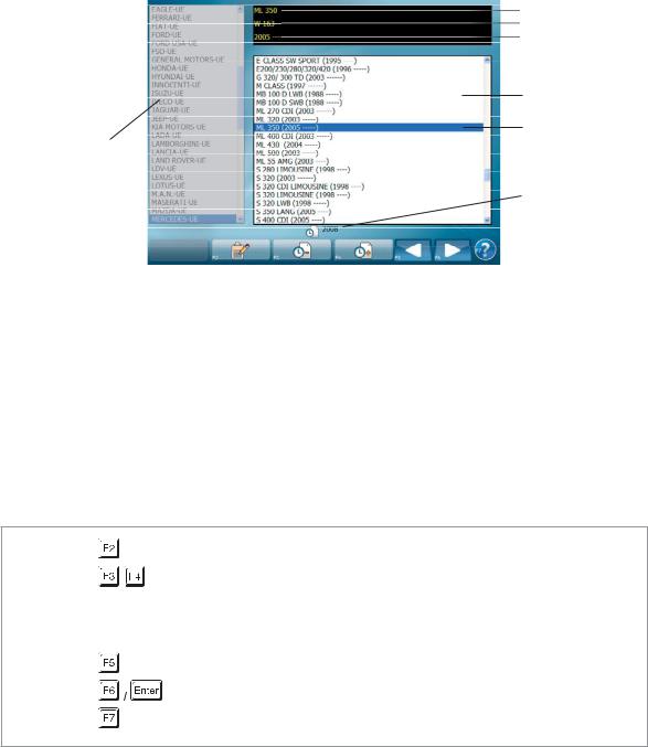
 4.3 - Selecting the vehicle model
After selecting the vehicle make, select the model for which you want to view the databank.
3a
3b
3c
2
3
1
4
1.Manufacturers
2.Models of the manufacturer selected registered in the year selected. A small square next to the model indicates that the vehicle is customised
3.Vehicle selected
3a. Model
3b. Sub-model or technical name
3c. Year of registration
4. Year of registration selected
If there are several identical models in list 2, you can distinguish them by selecting them one at a time and viewing the sub-model 3b.
: To insert customer informations
: Decreases/increases the year of registration with which the models are
filtered
 ...
... ,
, 

 : Model selection
: Previous page (vehicle make selection) 
: Confirms the model selected and goes to the database
: Help
I 0645 GB  18
18

5 - VEHICLE SPECIFICATIONS
The Vehicle Specifications page allows analysing the manufacturer's specifications to decide which operations are to be performed.
In most cases the manufacturer specifies the minimum, standard and maximum values for the main angles: toe-in, camber and caster.
Nevertheless, in some cases the manufacturer might:
•Require to position loads in the vehicle or fill the tank before making the measurement and adjustment
•Specify angles normally ignored: SAI, TOOT or maximum steerings
•Specify the maximum values for the difference between the right and left wheel camber or caster
•(car only) Prescribe a special adjustment method, as the 'Toe-in curve'
•Give different specifications based on the measurements of the ride height or the inclinations of parts of the suspension.
•Check some vehicle measurements (e.g. ride height or component tightening torque) or apply special tools (e.g. toe-in bar) before making the measurement and adjustment
On the Vehicle Specifications page you can see which of these things are required and decide whether or not to perform these operations.
You can also set the rim diameter in order to correctly display the toe-in in millimetres or inches and customise the vehicle specifications.
1.(car) Wheelbase and track (truck) Axles to which the specifications refer
2.Vehicle - make, model, sub-model or technical name, date of start and end of production.
3.Specifications. Minimum, standard and maximum values and maximum difference between the right and left wheels. The angles next to the vertical orange line refer to the front axle while those next to the blue line refer to the rear axle.
4.Rim diameter (inches)
5.If the 4-circle icon appears, the manufacturer requires the 'toe-in curve' adjustment method
6.If the wrench icon appears, the vehicle angle is definitely adjustable. If it does not appear, the angle might be adjustable any way.
7.If the camera icon appears during adjustment you can view the adjustment help images.
If you do not set the correct rim diameter when the toe-in is displayed in millimetres or inches, the measurement may differ from what is obtained when measuring the toe-in with a rule. Nevertheless, the rim diameter does not need to be set correctly in
order to correctly adjust the vehicle; it is sufficient to position the indicator in the green zone during adjustment.
I 0645 GB  19
19

: Displays any Adjustment Help Images  see paragraph 5.1


 see paragraph 5.2
: Displays the weights and percentage fuel in the tank  see paragraph 5.3
: 


 see paragraph 5.4
: Decreases/increases the rim diameter
5.1 - Adjustment help images
Selecting this option 

 a page is displayed showing the images of the mechanical adjustments that can be made on the vehicle being measured.
: Displays the next image
: Goes back to the Vehicle Specifications
I 0645 GB  20
20

5.2 - Ride height
To access this page, press  from the Vehicle Specifications page
The Ride Height page allows:
•Viewing which measurements on the vehicle are required by the manufacturer (ride height or inclination of parts of the suspension) and if necessary enter the results.
•Viewing which measurements to check on the vehicle before making the measurement and the adjustment (e.g. chassis height or component tightening torque)
•Viewing which special tools to apply (e.g. toe-in bar)
1.Vehicle
2.Images of the measurements to be made on the vehicle or the tools to be applied. Examples:
a.Position the toe-in bar
b.Measurements with rule
c.Measurements with inclinometer
3.Tables
Once the tools have been applied and the measurements made, consult the tables.
•If they indicate that you need to check that the measurement is within a certain tolerance interval and this is not the case, act on the vehicle adjustments to bring the measurements within tolerance.
•If they indicate that you need to enter the measurement made, select the row from the corresponding table. The vehicle specifications are modified as a result.
You are advised to follow the manufacturer's indications; if it is required to set the measurement and this is not done, average values are used for the specifications.


 : Selects one of the two tables
: Selects the value of the measurement made on the vehicle (used only
for tables that indicate that the modification selected must be entered)
: Goes back to the Vehicle Specifications page, if necessary changing
the values of the vehicle angles based on the measurements made
I 0645 GB  21
21
 Loading...