


|
|
Instructions for use |
|
I |
||
CONTENTS |
|
|
|
|
||
1 - GENERAL |
|
3 |
|
|||
|
1.1 |
- GENERAL SAFETY REGULATIONS |
|
|
3 |
|
|
1.1.1 - STANDARD SAFETY DEVICES |
|
|
3 |
|
|
|
1.2 |
- FIELD OF APPLICATION |
|
|
3 |
|
|
1.3 |
- OVERALL DIMENSIONS (STANDARD GUARD) |
|
|
3 |
|
|
1.4 |
- TECHNICAL DATA |
|
|
4 |
|
|
|
|
|
|
||
|
2 - HANDLING AND LIFTING |
|
|
4 |
|
|
|
3 - STARTUP |
|
|
4 |
|
|
|
3.1 |
- ANCHORING |
|
|
4 |
|
|
3.2 |
- ELECTRICAL CONNECTION |
|
|
5 |
|
|
|
|
|
|
|
|
|
3.3 |
- ADAPTER MOUNTING |
|
|
5 |
|
|
3.4 |
- WHEEL GUARD ASSEMBLY AND ADJUSTMENT (OPTIONAL) |
|
|
5 |
|
|
3.5 |
- WD SPACER |
|
|
5 |
|
|
|
|
|
|
||
|
4 - CONTROLS AND COMPONENTS |
|
|
5 |
|
|
|
4.1 |
- AUTOMATIC DISTANCE AND DIAMETER GAUGE |
|
|
5 |
|
|
|
|
|
|
|
|
|
4.2 |
- KEYBOARD AND DISPLAY |
|
|
6 |
|
|
4.2.1 - FUNCTION MENU MANAGEMENT |
|
|
7 |
|
|
|
|
|
|
|
||
|
5 - INSTRUCTIONS FOR USE OF THE WHEEL BALANCER |
|
|
8 |
|
|
|
5.1 |
- USING THE GAUGE INSTALLED ON THE MACHINE |
|
|
8 |
|
|
5.1.1 - DATA SETTING |
|
|
8 |
|
|
|
5.2 |
- AUTOMATIC PRESETTING |
|
|
8 |
|
|
5.2.1 - STEEL OR ALUMINUM WHEEL RIMS. SPRUNG COUNTERWEIGHTS |
|
|
8 |
|
|
|
5.2.1.1 - STATIC & COMBINED MODES |
|
|
9 |
|
|
|
5.2.2 - RIMS WITH INTERNAL COUNTERWEIGHT |
|
|
9 |
|
|
|
|
|
|
|
|
|
|
5.3 |
- MEASUREMENT RESULT |
|
|
10 |
|
|
5.4 |
- RECALCULATION OF THE UNBALANCE VALUES |
|
|
10 |
|
|
5.5 |
- EXACT POSITIONING OF THE ADHESIVE WEIGHT BY MEANS OF THE GAUGE |
|
|
11 |
|
|
WITH CLIPS |
|
|
|
||
|
5.6 |
- SPLIT FUNCTION (HIDDEN WEIGHT) |
|
|
12 |
|
|
5.7 |
- OUT OF BALANCE OPTIMIZATION |
|
|
13 |
|
|
5.8 |
- AUTOMATIC MINIMISATION OF STATIC UNBALANCE |
|
|
14 |
|
|
6 - SET-UP |
|
|
15 |
|
|
|
6.1 |
- AUTODIAGNOSTICS |
|
|
15 |
|
|
6.2 |
- AUTOCALIBRATION |
|
|
15 |
|
|
6.3 |
- MANUAL DIMENSION PRESETTING (use only in particular cases or for test) |
|
|
16 |
|
|
6.3.1 - STEEL WHEEL RIMS (use for setting dimensions in AUTOCALIBRATION) |
|
|
16 |
|
|
|
6.3.2 - ALUS RIMS |
|
|
16 |
|
|
|
6.3.2.1 - ALUS VARIANT WITH INSIDE CLAMP WEIGHT |
|
|
17 |
|
|
|
6.4 |
- AUTOMATIC GAUGES CALIBRATION |
|
|
17 |
|
|
|
|
|
|
||
|
6.4.1 - RIM DISTANCE GAUGE |
|
|
17 |
|
|
|
6.4.2 - DIAMETER GAUGEE40 MM |
|
|
18 |
|
|
|
7 - ERRORS |
|
|
19 |
|
|
|
7.1 |
- INCONSISTENT UNBALANCE READINGS |
|
|
20 |
|
|
8 - ROUTINE MAINTENANCE |
|
|
20 |
|
|
|
8.1 |
- REPLACING THE PROTECTION FUSES |
|
|
20 |
|
I 0615 GB - 1

I 0615 GB - 2

1 - GENERAL
► 1.1 - General safety regulations
The wheel balancer may only be used by duly authorized and trained personnel.
The wheel balancer must not be used for purposes other than those described in the instruction manual.
The wheel balancer must not be modified in any way except for those modifications made explicitly by the manufacturer.
Do not remove the safety devices. Any work on the machine must be carried out by specialised personnel only.
Avoid using strong jets of compressed air for cleaning.
Use alcohol to clean plastic panels or shelves (AVOID LIQUIDS CONTAINING SOLVENTS).
Before starting the wheel balancing cycle, make sure that the wheel is securely locked on the flange.
The machine operator must not wear clothes with flapping parts. Do not allow unauthorized personnel to approach the wheel balancer when the cycle is running.
Avoid placing objects in the base which could impair the correct operation of the wheel balancing machine.
► 1.1.1 - Standard safety devices
Stop push button for stopping the wheel under emergency conditions.
The wheel guard is not compulsory since the balancing speed is less than 100 min-1.
► 1.2 - Field of application
The machine is designed for balancing wheels of cars, light commercial vehicles or motorcycles weighing less than 75 kg. It can be operated in a temperature range of 0° to + 45° C.
The following functions are provided: ALUS; SPLIT; Unbalance optimisation; Autodiagnostics; Autocalibration.
► 1.3 - Overall dimensions (standard guard)
1 |
I 0615 GB - 3

► 1.4 - Technical data
Single-phase power supply |
115 / 230 V - 50/60 Hz |
Protection class |
IP 54 |
Max. power absorbed |
0,8 Kw |
Balancing speed |
< 100 min-1 |
Cycle time for average wheel (14 kg) |
6-8 seconds |
Max. resolution of measurement |
1 gram |
Position resolution |
± 1.4 ° |
Average noise |
< 70dB (A) |
Rim-machine distance |
0 - 265 mm |
Rim width setting range |
1.5” - 20” or 40 - 510 mm |
Diameter setting range |
10” - 30” or 265 - 765 mm |
2 - HANDLING AND LIFTING
2 |
2a |
NOTE: DO NOT LIFT THE WHEEL BALANCER USING OTHER GRIPS .
3 - STARTUP
► 3.1 - Anchoring
The machine can operate on any flat non resilient floor.
Make sure that the machine rests solely on the three support points provided (Fig.2a).
NOTE: If possible, it is advisable to anchor to the floor using relative mounting feet (see fig. 2a) in the event of continual use with wheels weighing over 35 Kg.
I 0615 GB - 4
► 3.2 - Electrical connection
The machine is supplied with a single-phase mains cable plus earth (ground).
The power supply voltage (and mains frequency) is indicated on the machine identification plate and cannot be changed. Connection to the mains must always be made by expert personnel.
The machine must not be set up without proper earthing.
Connection to the mains should be through a slow acting safety switch rated at 3 A (230V) or 8 A(115 V). See enclosed diagram.
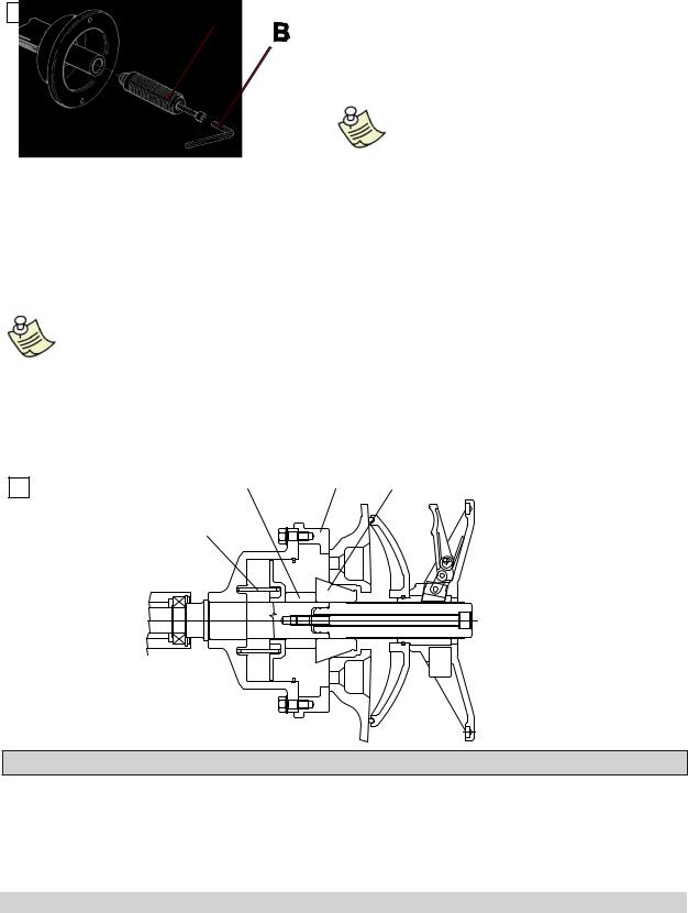
► 3.3 - Adapter mounting
3
The wheel balancer is supplied complete with cone adapters for fixing wheels with a central hole.
Other optional adapters can be mounted:
a.Remove the threaded end-piece A after unscrewing the screw B.
b.Mount the new adapter (see attached sheets).
NOTE: CAREFULLY CLEAN THE COUPLING SURFACES BEFORE PERFORMING ANY OPERATION.
► 3.4 - Wheel guard assembly and adjustment (optional)
1.Fasten the components to the base as illustrated in specific exploded view.
2.The position of the wheel guard when closed can be adjusted with relative screw accessible at the back. Correct position is horizontal.
3.Check that the microswitch is held down when the guard is closed.
4.Adjust the angular position of microswitch control.
Note: Do not lean on the guard during the wheel balancing cycle.
► 3.5 - WD spacer
When balancing very wide wheels (9”), there is not enough space to turn the distance gauge. To move the wheel away from the machine side, fit the WD spacer on the flange body and secure it with the standard issue nuts. When centring the wheel with cone from the inside, mount the DC spacer to obtain spring thrust.
DC |
WD |
Cone |
3a |
|
|
Spring |
|
|
4 - CONTROLS AND COMPONENTS
► 4.1 - Automatic distance and diameter gauge
Allows automatic measurement of the distance from the machine and the wheel diameter at the counterweight application point. The same gauge can be used to position the counterweights correctly inside the wheel, using the specifi c function that suggests the position memorised during measurement inside the rim.
I 0615 GB - 5

► 4.2 - Keyboard and display
4
|
|
|
1 |
|
|
|
|
|
|
|
2 |
|
|
|
|
|
|
|||||||
18 |
|
|
|
|
|
|
|
|
9 |
|
|
|
|
|
|
|
|
|
|
|
17 |
10 |
|
|
|
|
|
|
|
|
|
|
|
|
|
|
|
|
|
|
|
|
|
|
|||||
|
|
|
|
|
|
|
|
|
|
|
|
|
|
|
|
|
|
|
|
|
||||
|
|
|
|
|
|
|
|
|
|
|
|
|
|
|
|
|
|
|
|
|
|
|
||
|
8 |
|
|
|
|
|
|
|
|
|
|
|
8 |
11 |
||||||||||
|
|
|
|
|
|
|
|
|
|
|
|
|
|
|
|
|
|
|
||||||
|
|
|
|
|
|
|
|
|
|
|
|
|
|
|
|
|
|
|
14 |
15 |
||||
|
|
|
|
|
|
|
|
|
|
|
|
|
|
|
|
|
|
|||||||
|
|
|
|
|
|
|
|
|
|
|
|
|
|
|
|
|
|
|||||||
|
|
|
|
|
|
|
|
|
|
|
|
|
|
|
|
|
|
|
|
|
|
|||
13 |
3 |
|
|
|
|
|
|
|
|
|
|
|
4 |
|
|
|||||||||
|
|
|
|
|
|
|
|
|
|
|
|
|
|
16 |
12 |
|||||||||
|
|
|
|
|
|
|
|
|
||||||||||||||||
|
|
|
|
|
|
|
|
|
||||||||||||||||
|
|
|
|
|
|
|
|
|
|
|
|
|
|
|
|
|
|
|
|
|
|
|
||
|
5 |
|
6 |
|
|
7 |
|
|
|
|
|
|
|
|
||||||||||
|
|
|
|
|
|
|
|
|
|
|
|
|
|
|
|
|
|
|
|
|
|
|
|
|
1-2 Digital readouts, AMOUNT OF UNBALANCE, inside/outside
3-4 Digital readouts, POSITION OF UNBALANCE, inside/outside
5Inside correction mode selection button
6Indicators, correction mode selected
7Outside correction mode selection button
8Special function indicators
9Manual WIDTH/DISTANCE/DIAMETER setting buttons and MENU selection
10Push button, FUNCTION MENU
11Balancing cycle stop button
12Balancing cycle start button
13Position repeater push button
14Push button, SPLIT (unbalance resolution)
15MENU selection confirmation pushbutton
16Push button, unbalance reading < 5 g (.25 oz)
17Unbalance optimization selection pushbutton
18Grams/ounces selection pushbutton
Press buttons only with your fingers.
Do not use the counterweight grippers or other pointed objects.
I 0615 GB - 6
 Loading...