


|
Instructions for use |
|
I |
|
CONTENTS |
page |
|
||
1 - DESCRIPTION OF THE WHEEL BALANCER .......................................................................................................... |
3 |
|
|
|
1.1 |
- GENERAL ....................................................................................................................................................... |
3 |
|
|
1.2 |
- TECHNICAL DATA .......................................................................................................................................... |
3 |
|
|
1.3 |
- OVERALL DIMENSIONS ................................................................................................................................... |
3 |
|
|
1.4 |
- RECOMMENDATIONS ................................................................................................................................... |
4 |
|
|
1.5 |
- STANDARD SAFETY DEVICES ..................................................................................................................... |
4 |
|
|
2 - HOISTING AND INSTALLATION ............................................................................................................................... |
4 |
|
|
|
3 - COMMISSIONING ...................................................................................................................................................... |
5 |
|
|
|
3.1 |
- ELECTRICAL POWER SUPPLY ................................................................................................................... |
5 |
|
|
3.2 |
- PNEUMATIC CONNECTION .......................................................................................................................... |
5 |
|
|
|
3.2.1 - PRESSURE ADJUSTMENT FOR SPIN AND BRAKING DEVICE .................................................... |
5 |
|
|
4 - ASSEMBLY ............................................................................................................................................................... |
5 |
|
|
|
4.1 |
- ADAPTER MOUNTING .................................................................................................................................. |
5 |
|
|
4.2 |
- WHEEL MOUNTING ....................................................................................................................................... |
5 |
|
|
4.3 |
- GUARD MOUNTING AND ADJUSTMENT (OPTION) ....................................................................................... |
5 |
|
|
5 - CONTROL PANEL ..................................................................................................................................................... |
6 |
|
|
|
6 - PRESETTING OF DIMENSIONS .............................................................................................................................. |
7 |
|
|
|
6.1 |
- AUTOMATIC MEASUREMENT ...................................................................................................................... |
7 |
|
|
|
6.1.1 - STANDARD WHEELS ....................................................................................................................... |
7 |
|
|
|
6.1.2 - WHEELS WITH WEIGHTS INSIDE (ALU-S) .................................................................................... |
8 |
|
|
6.2 |
- MANUAL PRESETTING ................................................................................................................................. |
9 |
|
|
|
6.2.1 - STANDARD WHEELS ....................................................................................................................... |
9 |
|
|
|
6.2.2 - WHEELS WITH WEIGHTS INSIDE (ALU-S) .................................................................................. |
10 |
|
|
6.3 |
- PRESETTING WITH GAUGE EXTENSION ................................................................................................. |
11 |
|
|
6.4 |
- DOUBLE OPERATOR PROGRAM .............................................................................................................. |
11 |
|
|
6.5 |
- OPTIONS ...................................................................................................................................................... |
12 |
|
|
7 - WHEEL BALANCING .............................................................................................................................................. |
13 |
|
|
|
7.1- UNBALANCE MEASUREMENT .................................................................................................................... |
13 |
|
|
|
7.2 |
- RECALCULATION OF THE UNBALANCE .................................................................................................. |
13 |
|
|
7.3 |
- MINIMIZATION OF STATIC UNBALANCE ................................................................................................... |
14 |
|
|
7.4 |
- INDICATION OF COUNTERWEIGHT POSITION IN ALU-S ........................................................................ |
14 |
|
|
7.5 |
- STATIC - ALU ............................................................................................................................................... |
15 |
|
|
8 - UNBALANCE OPTIMIZATION ................................................................................................................................ |
16 |
|
|
|
8.1 |
- VISUAL WHEEL EXAMINATION .................................................................................................................. |
16 |
|
|
9 - SELF-CALIBRATION ............................................................................................................................................... |
17 |
|
|
|
9.1 |
- WHEEL BALANCER ..................................................................................................................................... |
17 |
|
|
9.2 |
- AUTOMATIC RIM DISTANCE GAUGE ......................................................................................................... |
17 |
|
|
10 - ERRORS ................................................................................................................................................................ |
18 |
|
|
|
10.1 - INCONSISTENT UNBALANCE READINGS .............................................................................................. |
18 |
|
|
|
11 - SELF DIAGNOSTICS ............................................................................................................................................. |
19 |
|
|
|
12 - ROUTINE MAINTENANCE (SEE EXPLODED DRAWINGS) ............................................................................... |
19 |
|
|
|
12.1 - TO REPLACE THE DRIVING PULLEY ......................................................................................................... |
19 |
|
|
|
12.2 - TO REPLACE THE BRAKE PAD ............................................................................................................... |
19 |
|
|
|
12.3 - TO REPLACE THE FUSES ........................................................................................................................ |
19 |
|
|
|
12.4 - MAINTENANCE OF THE SPECIAL PNEUMATIC CIRCUIT ...................................................................... |
19 |
|
|
|
13 - RECOMMENDED SPARE PARTS LIST ................................................................................................................ |
20 |
|
|
|
I 0147 GB - 1
I 0147GB - 2
1 - Description of the wheel balancer
1.1 - General
It is an electronic wheel balancer with microprocessor designed for balancing wheels up to 200 kg in weight. The controls and indicator devices are all mounted on the front panel.
The push button calibration system allows a sufficiently wide range of adjustment to cater for wheels other than the ordinary ones (motor cycles and racing cars).
Certain functions are available for wheels of unusual shape and for setting the optional functions of the wheel balancer. The machine is equipped with a built-in pneumatic lift to facilitate mounting of large size wheels. The lift is complete with a carriage running on castors with side bar having a dual function: ensuring operator safety and easier
axial displacement of the wheel.
1.2 - Technical data
Max. wheel diameter |
1300mm |
Max. wheel weight |
200 Kg |
Max. power consumption |
1,1 Kw |
Standard power supply |
115/230 V single phase 50/60 Hz |
Balancing accuracy |
1 g for car / 10 g for truck |
Balancing speed |
100 r.p.m. for car wheels |
|
70 r.p.m. for truck wheels |
Rim diameter |
10” to 26.5” or else 265 to 665 mm |
Rim width |
1.5” to 20” or 40 to 510 mm |
Cycle time |
8 to 20 sec |
Net weight with guard (excluding cone adapters) |
200 kg |
Sound pressure level during work cycle |
< 70 d B (A) |
Operating temperature range |
from 0° to 45° C |
Min/max. compressed air pressure |
8 to 10 Kg/cm2 .....approx 0.8 to 1 Mpa |
|
approx 8 to 10 Bar approx 115 to 145 PSI |
Protection class |
IP 54 |
- UNBALANCE DISPLAY PITCH |
|
|
Car = 5 g (0.25 Oz).................................... |
Truck = 50 g (1 Oz) |
|
When |
is pressed, the unbalance is displayed with pitch: |
|
Car = 1 g |
................................................... |
Truck = 10 g |
- UNBALANCE DISPLAY THRESHOLD |
|
|
Car = 5 g .......................................(.3 Oz) |
Truck = 50 g (2 Oz) |
|
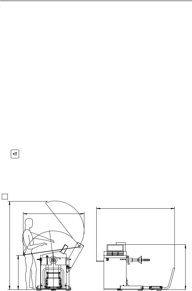
1.3 - Overall dimensions
1 |
1468 |
2125 |
820 |
1885
|
1080 |
I 0147 GB - 3 |
1.4 - Recommendations
-Before starting to use the balancing machine, carefully read the operating instruction manual.
-Keep the manual in a safe place for future reference.
-Refrain from removing or modifying machine parts as this would impair correct operation. Please get in touch with the Technical Service when needing repairs.
-Do not use strong jets of compressed air for cleaning.
-Use alcohol to clean plastic panels or shelves (AVOID LIQUIDS CONTAINING SOLVENTS).
-Before starting the wheel balancing cycle, make sure that the wheel is securely locked on the adapter.
-The machine operator should not wear clothes with flapping edges. Make sure that unauthorized personnel do not approach the balancing machine during the work cycle.
-Avoid placing counterweights or other objects in the base which could impair the correct operation of the balancing machine.
-The balancing machine should not be used for purposes other than those described in the instruction manual.
1.5 - Standard safety devices
-Low rotation speed.
-Stop push button for stopping the wheel under emergency conditions.
-The safety guard of high impact plastic is with shape and size designed to prevent risk of counterweights from flying out in any direction except towards the floor. A microswitch prevents starting the machine if the guard is not lowered and stops the wheel whenever the guard is raised.
-Protection system on LIFT control.
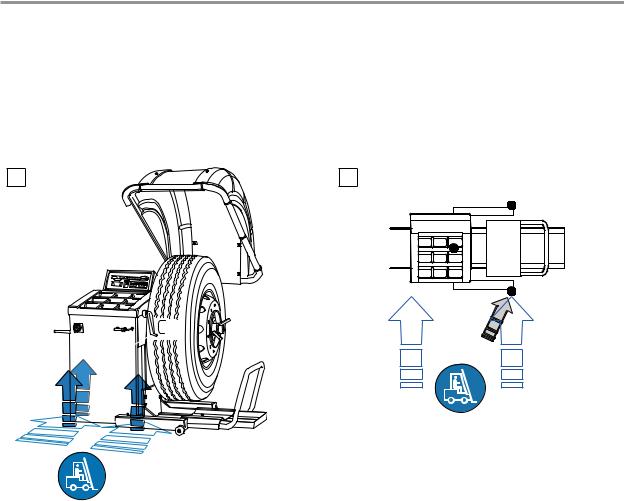
2 - Hoisting and installation
To hoist the machine, lever only on the base where the 3 support points are located. Never, under any circumstance, apply force to other points such as the spindle, head, side guard or accessory shelf.
Check that the balancing machine touches the floor at the three support points. The machine does not require anchoring to the floor for correct operation.
N.B.: The model without LIFT with protection must always be secured to the ground to ensure stability. The standard model with LIFT offers alternative options:
-Front wheel translation KIT
-Ground securing plate KIT
2 |
2a |
I 0147GB - 4

3 - Commissioning
3.1 - Electrical power supply
WARNING: The electrical connection must be made by specialized personnel. Connection to the single phase mains must be made between phase and neutral, and never, under any circumstances, between phase and earth (ground). Efficient earthing (grounding) is essential. The Manufacturer declines all responsibility and warranty in the event of incorrect connection.
Before connecting the machine to the mains through relative cable, check that the mains voltage matches the one shown on the nameplate at the back of the balancing machine. Rating of the electrical connection should be on the basis of the machine electrical power consumption (see nameplate).
-The machine mains supply cable should be fitted with a plug conforming to current regulations.
-It is recommended to provide the machine with its own electrical connection through a slow acting safety switch rated at 4 A (230 V) or 10 A (115 V).
-When connection is made directly to the main control panel without using any plug, it is advisable to padlock the main switch of the balancing machine in order to limit its use to authorized personnel only.
3.2 - Pneumatic connection
Connect the machine to the compressed air main. Do not use the machine if there is no pressure. Max. permissible inlet pressure is 10 kg/cm2 (approx. 10 bar or 145 PSI or 1Mpa). Make the connection to the pressure limiting unit at the back of balancing machine. The pneumatic circuit is designed to give the Lift considerable “flexibility” of movement in any position of its stroke; thanks to this the wheel position can be adjusted according to requirements with minimum manual effort.
3.2.1 - Pressure adjustment for spin and braking device
Use relative knob on the compressed air preparation unit to adjust the pressure. Average pressure setting is 4 to 5 kg/cm2 (approx. 4 to 5 BAR or 60 to 75 PSI or 0.4 to 0.5MPa).
N.B. An excessively high pressure could led to rapid wear on the rubber on the driving pulley.
Lubrication is essential for correct machine operation. Oil flow rate is adjustable via relative screw on the oil tank. Tighten or loosen the screw until a drop of oil falls per every 10 consecutive spins.
CAUTION! Only use mineral oil with average viscosity (30 cST at 40°C - WAIRSOL, LXOL grade).
4 - Assembly
4.1 - Adapter mounting
3
AB
The wheel balancer is supplied complete with cone type adapter for fastening wheels with central bore. Other optional adapters can be mounted:
a)Remove threaded end piece A after backing off screw
b)Mount the new adapter (see enclosed brochures).
4.2 - Wheel mounting
The wheels should be fastened with one of the numerous adapters builded by The Manufacturer (see enclosed brochures). N.B.: Incorrect centering inevitably causes unbalance.
4.3 - Guard mounting and adjustment (option)
a)Fasten the components to the base as illustrated in specifical exploded drawing.
b)The positions of these guards can be adjusted using the special screws accessed from inside the main support.
c)Check that the microswitch is held down when the guard is closed.
d)Adjust the angular position of microswitch control.
I 0147 GB - 5

5 - Control panel
1-2 Digital readout, UNBALANCE on inside/outside
3-4 Indicator, UNBALANCE POSITION on inside/outside
5 Indicator, correction mode selected
6 Push button, unbalance reading < 5 g (0.3 oz; options - calibration selection) 7 Push button, selection of correction mode
8 Pulsante per ricalcolo / autotaratura
9 Push button, manual DISTANCE setting
10Push button, manual WIDTH setting
11Push button, manual DIAMETER setting
12Push button, car/truck selection
13Push button, program selection
14Push button, cycle start
15Emergency push button, wheel lock/release
N.B. Never use the fingers to press the push buttons. Never use the counterweight pincers or other pointed objects.
I 0147GB - 6
 Loading...