


Portable equipment
N300
Vibrometer
Balancer
USER INSTRUCTION

|
Dichiarazione CE di Conformità |
|
|
EC-VerklaringvanOvereenstemming |
|
||
|
Declaration of Conformity |
|
|
Försäkran om CE-överensstämmelse |
|
||
|
EG-Konformitäts-Erklärung |
|
|
CE-overensstemmelses-erklæring |
|
||
|
Déclaration de Conformité |
|
|
CE-overensstemmelses-erklæring |
|
||
|
Declaration de Conformidad CE |
|
|
CE-vaatimusmukaisuus-vakuutus |
|
||
|
Declaração CE de Conformidade |
|
|
∆ήλωση Συµµόρφωσης CE |
|
||
|
La Ditta |
|
|
|
|
Het bedrijf |
|
|
|
|
|
|
|||
|
The Company |
|
|
|
|
Företaget |
|
|
Die Firma |
|
|
|
|
Virksomheden |
|
|
La Maison |
|
|
|
|
Virksomheten |
|
|
La Compañia |
|
|
|
|
Yhtiö |
|
|
A Empresa |
Costruzioni Elettro Meccaniche ing. Buzzi & C. S.p.a. |
Η εταιρία |
||||
|
|
|
|||||
|
|
|
Via Risorgimento, 9 |
|
|||
|
|
23826 MANDELLO DEL LARIO - (Lecco) ITALY |
onvereenstemming van het product |
||||
|
dichiara con la presente la conformità del Prodotto |
|
verklaart bij deze de |
||||
|
herewith declares conformity of the Products |
|
|
|
försäkrar härmed att produkten |
||
|
erklärt hiermit die Konformität desProdukts |
|
|
|
erklærer herved, at produktet |
||
|
déclare par la présente la conformité du Produit |
|
|
|
bekrefter herved at produktet |
||
|
Declare la conformidad del Producto |
|
|
|
vakuttaa että tuote |
||
|
com a presente declara a conformidade do Produto |
|
∆ηλώνει µε την παρούσα τη συµβατότητα του Προϊόντος |
||||
|
|
|
|
|
|||
|
Strumento |
|
|
Instrument |
|||
|
Instrument |
|
|
Instrument |
|||
|
Instrument |
|
|
Instrument |
|||
|
Instrument |
|
|
Instrument |
|||
|
Instrumento |
|
|
Instrument |
|||
|
Instrumento |
|
|
Όργανο |
|||
Tipo
Type
Typ
Type
Tipo
Tipo
Nr. di serie
Serial Number
Fabriknummer, usw
Numero de série
Numero de fabricacion
Número de série
Numero Distinta Base
Manufacturing List Number
Erstellungsliste nummer
Numéro de liste de construction
Numero lista de base
Número da Lista de Base
N300
--------------------
48AN64013
Type
Typ
Type
Type
Tyyppi
Τύπος
Serienummer
Serienr
Serienr
Serienr
Sarjanro
Αρ. Σειράς
Nummer basislijst
Produktionslistans nr.
Produktionslistens nr.
Produksjonslistens nr.
Valmistusluettelon nro.
Αριθµός Καταλόγου Παραγωγής
alle norme sottostanti / with applicable regulations below / mit folgenden einschlägigen Bestimmungen / selon les normes ci-dessous / con directivas subaplicables / com as normas indicadas em baixo / met de onderstaande normen / överensstämmer med följande föreskrifter / stemmer overens med følgende forskrifter
on yhdenmukainen seuraavissa laeissa olevien ehtojen kanssa / στους παρακάτω κανονισµούς
Direttive CEE / EC Directive / EG Richtlinie / Directive CEE / Directivas CE / Directivas CEE / EEG-richtlijnen
EU-direktiv / EØF-direktiver / EU-direktiver / EU-direktiivit / Οδηγίες CEE
2006/95/CE – 2004/108/CE
Norme Armonizzate Adottate /Applied Armonized Standards / Angewendete Harmonisierte Normen / Normes Harmonisées Appliquées / Normas Aplicadas en Conformidad / Normas Harmonizadas Aplicadas / Toegepaste geharmoniseerde richtlijnen / Standarder / Standardit / Εναρµονισµένοι Εφαρµοζόµενοι Κανονισµοί
EN 12100-1:2005 |
|
EN 12100-2:2005 |
|
EN 294:1993 |
|
EN 349:1993 |
|
|
|
|
|
|
|
|
|
EN 418:1992 |
|
EN 457 :1993 |
|
EN 60204-1:2006 |
X |
EN 60439-1:1990 |
X |
|
|
|
|
|
|
|
|
EN 61000-6-3/A11:2005 |
X |
EN 61000-6-1/IS1:2006 |
X |
EN 61000-6-4-:2002 |
X |
EN 61000-6-2:2006 |
X |
|
|
|
|
|
|
|
|
Data / Date / Datum / Date / Fecha / Data |
Firma /Signature / Unterschrift /Signature / Firma / Assinatura |
Datum / Datum / Dato / Pvm / Ηµεροµηνία |
Handtekening / Underskrift / Allekirjoitus / Υπογραφή |
16/03/2009 |
CEMB Spa |
|
Ing. Carlo Buzzi |
|
|
|
M06PRG01 |

N300 rev. 1.2 |
|
|
|
|
Table of contents |
||
Chapter 1 - General description |
|
|
|
||||
|
|
|
|
|
|||
¾ |
Standard accessories |
……………………………… |
1 - 1 |
||||
¾ |
Optional accessories |
……………………………… |
1 - 2 |
||||
¾ |
Inputs |
|
……………………………….……… |
1 - 2 |
|||
¾ |
Reset button |
……………………………………… |
1 - 3 |
||||
¾ |
Battery |
……………………………………………… |
1 - 4 |
||||
¾ |
Adjustment and calibration…………………………. ..… |
1 - 5 |
|||||
¾ |
General advice |
……………………………………… |
1 - 5 |
||||
Chapter 2 - General overview |
|
|
|
|
|||
|
|
|
|
|
|||
¾ |
Keypad |
……………………………………………... |
2 - 1 |
||||
¾ |
Start / Stop acquisition functions ……………………… |
2 - 3 |
|||||
¾ |
Changing the channel displayed |
………………….…... |
2 - 3 |
||||
¾ |
Specific additional functions for the various pages…….... |
2 - 3 |
|||||
Chapter 3 - Initial screen (menu) |
|
|
|
||||
|
|
|
|
|
|
||
Chapter 4 - Setup function |
|
|
|
|
|||
|
|
|
|
||||
¾ |
Sensor sensitivity ……………………………….……. |
4 - 1 |
|||||
¾ |
Date |
……………………………………….……. |
4 - 2 |
||||
¾ |
Time |
………………………………………….…. |
4 - 3 |
||||
¾ |
Units of measurement system |
…………….…….…. |
4 - 3 |
||||
¾ |
Display brightness ……………………….……..…...…. |
4 - 3 |
|||||
¾ |
Backlighting auto-off time …………………………..…. |
4 - 3 |
|||||
¾ |
Instrument auto-off time ………………………..……. |
4 - 3 |
|||||
Chapter 5 - Vibrometer function |
|
|
|
||||
|
|
|
|
|
|||
¾ |
Measurement setting |
………………………….…. |
5 - 1 |
||||
¾ |
Settings only valid for Overall measurements ……... |
5 - 3 |
|||||
¾ |
Settings only valid for synchronous measurements….…. |
5 - 4 |
|||||
¾ |
Measurement results |
………………………….….. |
5 - 5 |
||||
¾ |
Additional functions |
………………………….….. |
5 - 8 |
||||
Table of contents |
1 |

Chapter 6 - Balancing function
¾ Imbalance measurement and correction calculation.……….. |
6 - 3 |
||
¾ |
Additional functions |
………………………………… |
6 - 5 |
¾ |
Displaying balancing results from the records ……….… |
6 - 5 |
|
¾ |
Measurement settings |
………………………………… |
6 - 7 |
Chapter 7 - CEMB N-Pro program (optional)
¾ |
System requirements |
…………………………….… |
7 |
- 1 |
||
¾ |
Installation of the software |
………………………. |
7 |
- 1 |
||
¾ Installation of drivers for USB communication |
|
|
||||
|
with N100 and N300 instruments ……………………… |
7 |
- 2 |
|||
¾ |
Activating the software |
……………………………… |
7 |
- 4 |
||
¾ |
Use of the software |
…………………………..….. |
7 |
- 5 |
||
¾ |
Function bar |
……………….………………….….. |
7 |
- 5 |
||
¾ |
General settings |
………………….…………………... |
7 |
- 6 |
||
¾ Reading data from the N100 or N300 instrument ………. |
7 |
- 7 |
||||
¾ Data records imported from the N100 or N300 instrument |
7 - 8 |
|||||
¾ |
Displaying data present in the records ………………. |
7 |
- 9 |
|||
¾ |
Generation and printing of certificates (reports) ……..… |
7 |
– 12 |
|||
¾ Generation and printing multiple |
|
|
|
|||
|
measurement certificates (multi-report) ………………..... |
7 |
- 13 |
|||
Appendix A - Technical data Appendix B - Judgement criteria
Appendix C - Guide to interpreting a spectrum
Appendix D - Information related to the creation of customised Templates (models) for certificates generated by the CEMB N-Pro program.
Appendix E - List of symbols used for the instrument
Attachment: Balancing precision for rigid rotating bodies
2 |
Table of contents |
Chapter 1
General description
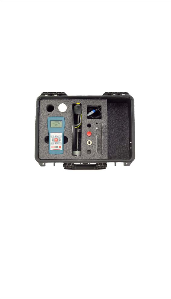
The N300 instrument and its accessories are supplied in a strong, solid case designed to withstand demanding environments (steelworks, refineries, workshops, etc) and air travel. It can also be locked with a padlock for greater security.
We recommend the instrument is returned to its case after every use to protect it from damage during transport.
Standard accessories:
-N300 instrument complete with battery -battery charger
-1 TA-18S accelerometer transducer -1 transducer connection cable
-1 magnetic base -1 probe
-18,000 RPM photocell complete with upright and magnetic base -roll of reflecting tape
-graduated disc for angular measurements -multilingual manual on CD-ROM
-heavy duty, high resistance, water and air-tight carrying case. -“Getting started” leaflet with basic instructions for use
General description |
1 - 1 |
Optional accessories:
-diameter 40 velocity transducer complete with connection cable, magnetic base and probe
-optic fibre photocell (60,000 RPM) complete with upright and magnetic base
-10m-long extension cable for transducers
-10m-long extension cable for standard photocell
-1 USB data cable
-CEMB N-Pro software for saving, managing and printing data.
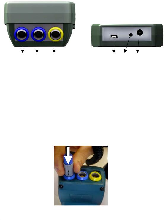
Inputs
1 |
2 |
3 |
4 |
5 |
6 |
1– channel A sensor input
2– channel B sensor input
3– photocell input for velocity measurement
4– type B mini USB port for connection to PC
5– instrument reset button
6– battery charger connector
The sensors and photocell can be connected by simply inserting the connector into the relative socket, pushing it in until a "click" is heard; make sure that the safety connection is aligned correctly, as shown in the illustration.
1 - 2 |
General description |

To extract the connector, press the terminal part (blue or yellow) and simultaneously pull the main body (grey), to release it.
Warning:
Do not try to pull the connector out with force without releasing it as described above as it could damage it.
Reset button
In some special circumstances, CEMB customer service may advise you to reset the N300 instrument. To do this, press the button located on the lower part of the instrument using a small object with a rounded tip. It is purposely located in a difficult to access area to prevent it from being reset unintentionally.
Warning:
In the event of an error that cannot be reset automatically, the message "Err" will be displayed on the screen followed by the number identifying the error that occurred.
Should this situation occur, the instrument must be reset manually by pressing the reset button.
Warning:
Do not use pointed objects such as needles, punches or suchlike to press the reset button as they could damage it.
General description |
1 - 3 |

Battery
The N300 instrument is equipped with an integral rechargeable lithium battery, offering a battery life of more than ten hours under normal operating conditions.
The battery status is indicated by an icon in the upper right hand corner of the screen.
- |
battery fully charged |
- |
battery partly charged |
- |
battery almost flat (battery life remaining when this appears is approx. one |
|
hour) |
- |
battery flat: recharge within 5 minutes |
If the battery is flat and the instrument is not recharged within 5 minutes it will switch off. This would interrupt any active measurements not yet saved.
When the battery charger is connected the display lights up briefly indicating the connection, even when the instrument is switched off.
The battery icon remains animated when the instrument is recharging, progressively filling up. When charged, the animation stops and the ‘battery fully charged’ icon is shown.
Warning
When connecting the battery charger, first insert the connector into the relevant socket on the N300 instrument; only plug it into the power supply socket when this has been done.
When recharged, unplug the battery charger from the power supply socket before removing the connector from the instrument.
Warning:
We strongly recommend recharging the instrument when switched off; as charging takes less than five hours, avoid leaving the battery connected for an excessively long period of time (maximum 12 hours).
Warning:
The lithium battery withstands frequent charging-discharging cycles easily, even on a daily basis, however allowing it to run out completely can damage it. For this reason we recommend it is charged at least once every three months, even when not used for long periods of time.
Note:
As the display backlighting consumes the most power, it switches off automatically after a certain period of time (settable) has passed without pressing any key. Pressing any key (excluding  ) will reactivate it.
1 - 4 |
General description |
 Warning:
Recharge the instrument before storing it if you do not intend to use it for a long period of time. In this case, remember to recharge it every 3 months: the internal clock also consumes power (even though the amount consumed is low), therefore after a long period of disuse it is possible that the battery will be flat.
Alternatively, the battery can be disconnected before storing the instrument for long periods of time: remember that in this case the date and time will need resetting the next time the instrument is used. In the case of the second hypothesis, to maximise the battery life it should be fully charged at least every 8-9 months.
Adjustment and calibration
Before delivering the N300 instrument to the client, CEMB laboratories subject it to a complete adjustment, calibration and test procedure to guarantee it works correctly.
General advice
Store and use the instrument away from sources of heat and considerably strong electromagnetic fields (high-power inverters and electric motors).
Measurement precision can be invalidated by the connection cable between the transducer and the instrument, therefore we recommend that:
-the cable does not share the same path as the power cables;
-any power cables crossed should be overlapped perpendicularly;
-the shortest possible cable should be used; in fact floating lines act as active and passive aerials.
Warning:
Always pay the utmost attention during measurement operations, using suitable protective devices when possible to safeguard the operator from moving parts When not possible, always leave an adequate safety distance between them.
General description |
1 - 5 |

1 - 6 |
General description |

Chapter 2
General overview
Keypad
The keyboard on the CEMB N300 instrument has a limited number of keys, enough to guarantee easy and intuitive use.
- on/off key
Press this key to turn the instrument on; hold it down for at least 3 seconds to turn it off, then release the key.
Note: |
|
After pressing |
, the instrument’s serial number and the version of the firmware |
installed will be displayed briefly in the lower part of the screen. In the event of any problems, take note of this data before contacting CEMB customer service to enable us to provide you with a better service.
- OK key
In the main screen it confirms the selection made and opens the corresponding page.
In the Setup screen it confirms the value of the parameter selected.
In the Vibrometer and Balancing screens it performs different functions:
-it confirms values when setting acquisition parameters
-it stops or starts the measuring process (see 2-3 Start/stop acquisition function).
-when the additional functions bar is visible it is used to select the desired
function
In the records screen it opens the desired function from the additional functions bar.
General overview |
2 - 1 |

- back key
Press this key to quit the current screen and return to the previous one. It can also be pressed when setting parameters to end the operation without changing any values.
- function key (F)
When available, it displays the additional functions bar in the lower part of the screen.
- set key (SET)
In the settings screen it enables the “edit” function for the parameter selected.
In the Vibrometer and Balancing screens it enables the “edit” function for all of the measurement parameters.
- change channel key (A/B)
 In the measurement screens, it changes the channel displayed.
- directional arrows
They change the element selected, recognizable because displayed in negative (white on a black background), or they change the value of that which is being set.
2 - 2 |
General overview |
Start/Stop acquisition function
In all measurement screens acquisition is started by pressing |
and is later stopped by |
|
pressing the same |
. |
|
The acquisition enabled status is easy to identify by the presence (in the upper left hand corner of the screen, below where the channel displayed is indicated) of an arrow rotating to describe a circumference.
In the first few moments after the start of every measurement, the N300 instrument can automatically determine the most suitable amplification based on the signal received from the sensors.
If the vibration is higher than the instrument's limits of operation (see Appendix A), the channel saturation symbol  will be displayed.
Changing the channel displayed
To ensure maximum clarity in the presentation of data, the N300 instrument always displays one channel at a time, indicated respectively by the symbol  or
or 
In the event that both measurement channels are to be used for the measurement, the channel displayed can be changed by pressing the  key.
key.
Specific additional functions for the various pages
The specific additional functions available in each page can be displayed by pressing the  key. A bar will appear in the lower part of the screen, from which the desired
function can be selected using the |
and |
arrows, and confirmed by pressing the |
key . |
|
|
Press  to quit the bar without selecting anything.
General overview |
2 - 3 |
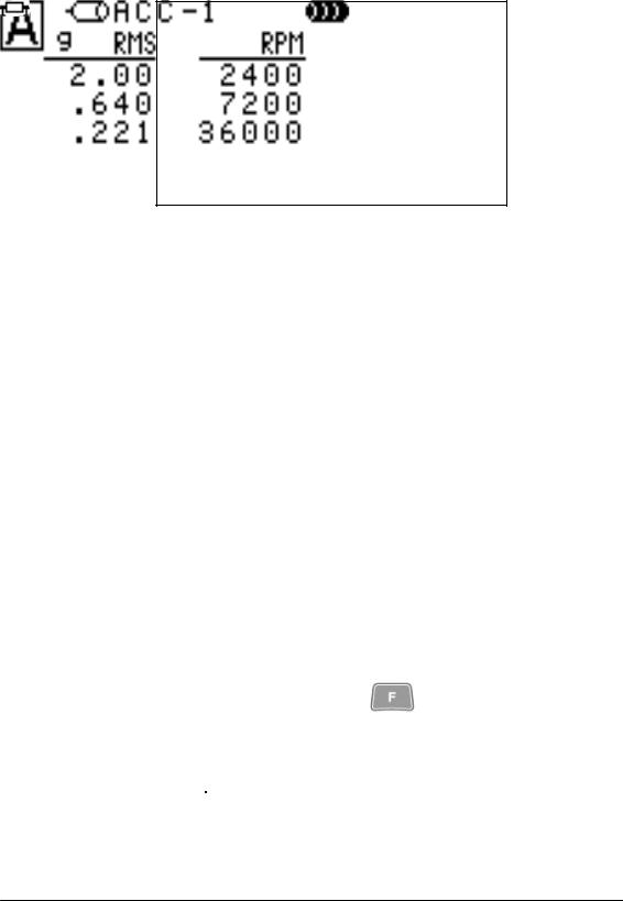
- List of peak values
When selected, this function displays a table containing the amplitudes of the highest components of the signal, with the corresponding frequency listed beside each one. Up to five peak values are listed in descending order, irrespective of their frequency. If the signal measured is composed of a lower number of significant components, a lower number of peak values will be displayed.
Use the  key to switch between displaying channel A peaks and channel B peaks.
Press the  key to exit this page and return to the vibrometer screen.
- Measurement records
With the N300 instrument, measurements taken or balancing operations performed can easily be saved in two different records:
- vibration measurement records |
(24 positions) |
symbol |
- balancing data records |
(10 positions) |
symbol |
The size of the vibration measurement records is optimised to contain all of the measurements for a typical real situation: detection in the three orthogonal directions on four supports, before and after maintenance work on machinery composed of two elements (motor and pump, or motor and fan).
In the Vibrometer and Balancing screens, press |
and then select the symbol |
 in the additional functions bar to open the corresponding records page.
The symbol in the upper part identifies the current record, in which every position is marked with the symbol  and a sequential number; empty positions are marked by the symbol -----, the others contain the date and time that their contents were saved, shown as DD/MM/YY HH:mm, where:
-DD is the day of the month (from 1 to 31)
-MM is the month of the year (from 1 to 12)
2 - 4 |
General overview |

-YY are the last two figures of the year (08 for 2008, 09 for 2009, …)
-HH is the time of day (from 00 to 23)
-mm are the minutes of the hour (from 00 to 59)
The position to open can be selected using the  and
and  arrows, then the additional functions bar must be displayed and one of the following operations must be selected:
- |
save the measurement (or balancing operation) performed. |
|
The current date and time are automatically used to identify the data |
|
recorded. |
|
In the case of two-channel acquisition, data is automatically saved in the |
|
same position of the record for both channels. |
|
Note: |
|
|
|
If the position selected is already in use, before saving the data the |
symbol |
|
|
asks the operator to confirm that the data should be overwritten. Press |
to |
|
|
confirm; the |
key interrupts the saving procedure and another position can |
|
|
be selected. |
|
|
- |
load the measurements (or balancing operation) selected |
|
|
|
Loading data from the records allows the user to view results saved |
||
|
previously in a relevant screen, described respectively in |
|
|
|
5-8 Displaying measurements from the records and 6-5 Displaying |
||
|
balancing results from the records. |
|
|
- |
delete the measurement selected, emptying the relative position in the |
||
|
records. |
|
|
- |
delete all of the measurements, emptying the records completely. |
|
|
General overview |
2 - 5 |

Note:
Before deleting data from the records, the symbol |
asks the operator to |
confirm the operation, which will result in the data being deleted definitively. Press
the |
key to confirm; with |
, the data will not be deleted. |
Note: |
|
|
The |
and |
keys, which respectively increase and decrease the position |
selected by 3, |
can be used to scroll through the records quickly. |
|
2 - 6 |
General overview |
Chapter 3
Initial screen (menu)
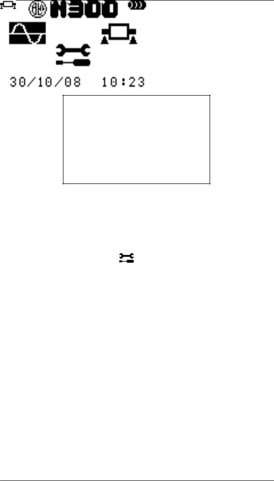
When turned on, the Instrument model N300 displays the main screen
containing the CEMB symbol, the instrument’s name, the battery status, the date and time and the icons used to access the various pages:
–
–
–
Vibration measurement Balancing
General settings (setup)
After selecting the desired page using the  and
and  arrows, press
  to open it.
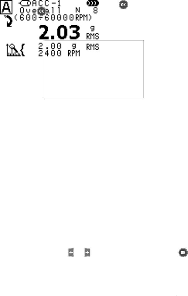
1.Vibrometer
-measurement of the total vibration value (Overall), together with the amplitude and frequency of the highest component (main peak value)
-measurement of the vibration modulus and phase at the synchronous frequency at the velocity of the rotating body or its multiples (1xRPM, 2xRPM, 3xRPM, 4xRPM and 5xRPM)
2.Balancing
-field balancing of rotating bodies with one or two correction planes
3.Setup
-setting of the degree of sensitivity of sensors connected to the instrument
-setting the instrument’s general operating parameters
Initial screen |
3 - 1 |
The data transfer function, identified by a relative screen, opens automatically when a USB cable is inserted into the port of the N300 instrument and that of a PC whilst the first screen is displayed.
In this state the PC acts as master, whilst the N300 instrument acts as a simple slave, therefore pressing keys no longer has any effect.
Once the data has been transferred to the PC (see Chapter 7–6 Reading data from the N300 instrument), disconnect the USB cable to return to the main panel.
3 - 2 |
Initial screen |
Chapter 4
Setup function
All of the parameters required for correct operation of the N300 instrument can be set in the setup screen. You can scroll up and down the list of parameters that can be set using the and arrows.
The parameter selected will be displayed in white on a black background (in negative).
To edit the value press the |
key, insert the desired value when requested to do so, |
then confirm with the |
key. |
To quit the edit function without changing the previous value press  .
.
Sensor sensitivity
The N300 instrument can be used with various types and models of sensors, and therefore for correct measurements you must set the exact degree of sensitivity (= number of volts per unit) of those effectively connected. Press the key to vary the sensitivity of the sensor selected, varying one figure at a time.
The |
and |
arrows increase or decrease the figure selected (displayed in |
negative) by one unit. |
|
|
By pressing |
and |
, the figure on the left or on the right can be selected respectively. |
Setup function |
4 - 1 |
Note:
Although the instrument can operate correctly with any combination of sensors, we recommend that sensors of the same type and model are connected to the two channels.
For both possible types:
- |
accelerometer |
ACC |
- |
velocimeter |
VEL |
- |
displacement |
DIS |
two different sensitivity levels can be set, identified respectively by “1” and “2”. Therefore six different sensors can be defined:
-ACC-1 accelerometer 1 (powered – IEPE type)
-ACC-2 accelerometer 2 (powered – IEPE type)
-VEL-1 velocimeter 1(not powered)
-VEL-2 velocimeter 2(not powered)
- |
DIS-1 |
displacement sensor 1 (not powered) |
- |
DIS-2 |
displacement sensor 2 (not powered) |
making it possible to use the same types of sensors but with different sensitivity levels.
Typical sensitivity values for the various sensors are:
SENSOR TYPE |
SENSITIVITY |
TYPICAL VALUE |
|
|
|
Accelerometer (ACC) |
mV/g |
100 |
|
|
|
Velocimeter (VEL) |
mV/(mm/s) |
21,2 |
|
|
|
Displacement (DIS) |
mV/µm |
8 |
|
|
|
Warning:
The sensitivity of some models may differ from the typical values shown; make sure that the sensor is set with the correct value taken from its documentation.
Date 
The date must be entered in the N300 instrument using two figures for the day, two for the month and two for the year, in this order. To assist the operator, the dd/mm/yy format is displayed below the current date.
New values can be entered following the same procedure as that described above for the sensitivity of the sensors (see above).
4 - 2 |
Setup function |

Time 
Time must be entered in the N300 instrument using two figures for the hours (from 00 to 23) and two for the minutes (from 00 to 59). To assist the operator, the hh:mm format is displayed below the current time.
New values can be entered following the same procedure as that described above for the sensitivity of the sensors (see above).
Units of measurement system 
The units of measurement used for acceleration, velocity and movement values can be respectively:
-g; mm/s; µm : metric units
-g; inch/s; mils : imperial units
After pressing the |
key, you can scroll through all of the possibilities using |
|
the |
and |
arrows. |
Display brightness
The brightness of the display can be adjusted to provide excellent visibility in various environmental conditions, from minimum (no backlighting) to maximum. This is possible using the  and
and  arrows after having enabled the “enter values”
mode by pressing  .
.
Backlighting auto-off time
To extend the duration of the battery before it needs recharging, the display backlighting turns off automatically after a preset amount of time (settable from 1 to 255 seconds) has passed since the last key was pressed. Pressing any key reactivates the backlighting.
Instrument auto-off time
To extend the duration of the battery before it needs recharging, the instrument turns off automatically after a preset amount of time (settable from 5 to 60 minutes) has passed since the last key was pressed. To use the instrument again, turn it on by pressing 
Setup function |
4 - 3 |
Chapter 5
Vibrometer function
One of the simplest, but at the same time most important, values in vibration analysis is the overall value of the vibration itself. This is often the first parameter to consider when assessing the operation of a motor, fan, pump, machine tool, etc.
Suitable tables are used to discriminate between an excellent condition or a good, acceptable, tolerable, unacceptable or even dangerous condition. (see Appendix B – Judgement criteria).
In some cases it may be interesting to know the synchronous vibration modulus and phase values, that is to say corresponding to the rotating body’s rotation velocity (1xRPM), or its multiples (2xRPM, 3xRPM, 4xRPM, 5xRPM).
The vibrometer function can be used to take this type of measurement easily and intuitively, saving the results in a special record.
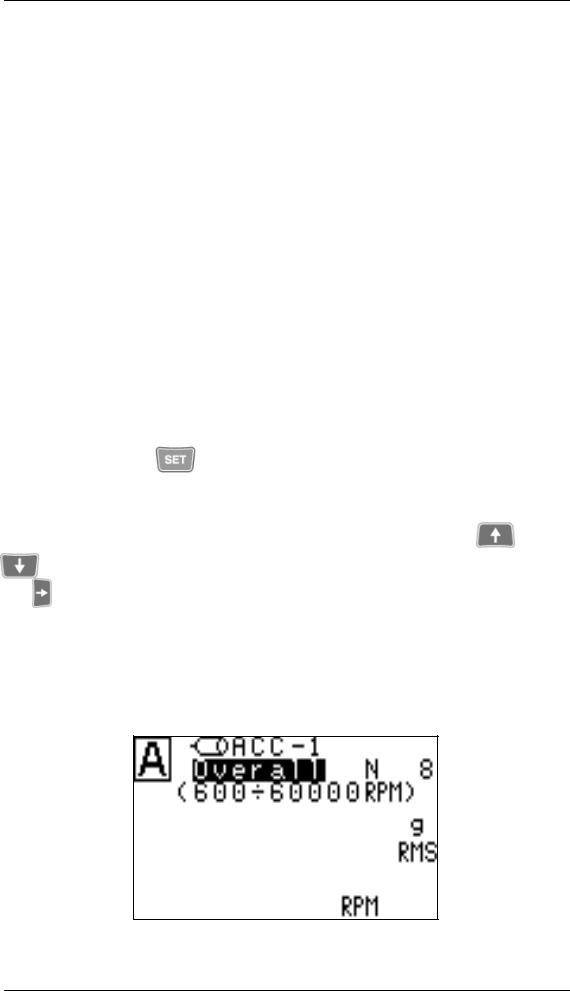
Measurement settings
The settings used to measure vibration are all displayed in the Vibrometer page and can be adjusted by pressing the key: for greater clarity all measurement results are hidden, with only adjustable parameters remaining visible. Before changing the settings make sure that the channel displayed in the upper left hand corner is the one that you wish to change; otherwise change it using the  key .
key .
The parameter that can be changed is displayed in negative, by pressing the and the arrows you can scroll through all of the values that can be selected. With the 
and |
keys, you can move to the previous or next parameter. |
These can be divided into two categories:
−specific, only valid for the channel displayed at that time
−common, which automatically apply to both: this group includes anything concerning the type of measurement required
Vibrometer function |
5 - 1 |

1. Enabling/Disabling a channel:
Each of the measurement channels of the N300 instrument can be:
-
-
enabled when you wish to connect a sensor and take a measurement disabled when no sensor is connected
In the event that a channel is disabled, all of the other measurement settings disappear, and
pressing |
displays the OFF message. |
2. Sensor type:
One of the sensors for which the sensitivity has been set must be selected (see 4.1 –
Sensor sensitivity):
−
−
−
−
−
−
ACC-1 : type 1 accelerometer (powered – IEPE type) ACC-2 : type 2 accelerometer (powered – IEPE type) VEL-1 : type 1 velocimeter (not powered)
VEL-2 : type 2 velocimeter (not powered)
DIS-1 : type 1 displacement sensor (not powered) DIS-2 : type 2 displacement sensor (not powered)
When required, the N300 instrument automatically supplies power to the sensors connected.
Warning:
To obtain a sufficiently accurate measurement the sensor effectively connected must be correctly associated with each channel.
3. Measurement:
Indicates the type of measurement carried out:
−Overall: overall vibration value
−Synchronous measurement: value of the synchronous component at the rotation velocity (1xRPM) or its multiples (2xRPM, 3xRPM, 4xRPM, 5xRPM)
4. Units of measurement
Select the unit of measurement in which the vibration is to be expressed: the possibilities are:
−acceleration (g)
−velocity (mm/s or inch/s)
−movement (µm or mils)
Warning:
Displacement and speed measurements can be taken when displacement sensors are used, however their use means acceleration measurements cannot be taken.
5 - 2 |
Vibrometer function |

5. Type of vibration
Like all physical sizes, vibration has a value that can vary from one moment to the next; mathematically it can be described by a function of time. Its overall value can therefore be calculated in three different types:
−RMS (Root Mean Square): mean square value
the mean value of the previously squared vibration;
the most commonly used, especially for acceleration or velocity measurements. It is a direct indication of the vibration’s “energy” content: in practice it represents the power brought with the vibration and discharged onto the supports or bases of the vibrating structure.
−PK (Peak): peak value
the maximum value reached by the vibration in a certain period of time.
−PP (Peak-to-Peak): peak-to-peak value
the difference between the maximum value and the minimum value reached by the vibration in a certain period of time;
normally used for movement measurements.
6.Units of frequency
Indicates how to display the velocity and frequencies, and can be chosen from: - Hz – cycles (revs) per second
− RPM – revs per minute
Note:
The relation 1 Hz = 60 RPM clearly exists between the two units
Settings only valid for overall measurements
1. Frequency range:
The overall vibration value usually originates from the sum of various contributions, caused by various phenomena, which are therefore associated with different frequencies. Depending on the situation, you may only wish to consider those corresponding to a certain range of frequencies in overall measurement:
−1-100 Hz if the interest is limited to phenomena with low frequencies
−2-200 Hz if the interest is limited to phenomena with relatively low frequencies
−5-500 Hz if the phenomenon also involves average frequencies
−10-1000 Hz to comply with the conditions set forth in the ISO 10816-1 standard (typical)
Note:
A commonly used practical consideration is to check that the maximum frequency is set to at least 20-30 times that of the rotation of the shaft examined. This means
Vibrometer function |
5 - 3 |
 Loading...