


Operating instructions |
I |
Contents
1- GENERAL |
3 |
|
1.1 |
- GENERAL SAFETY RECOMMENDATIONS |
3 |
1.1.1 - STANDARD SAFETY DEVICES |
3 |
|
1.2 |
- FIELD OF APPLICATION |
3 |
1.3 |
- OVERALL DIMENSIONS (42" GUARD) |
3 |
1.4 |
- SPECIFICATION |
4 |
2 - HANDLING AND LIFTING |
4 |
|
3 - COMMISSIONING |
5 |
|
3.1 |
- ANCHORING |
5 |
3.2 |
- ELECTRICAL CONNECTION |
5 |
3.3 |
- ADAPTER MOUNTING |
5 |
3.4 |
- GUARD MOUNTING AND ADJUSTMENT |
6 |
3.5 |
- SPACER WD |
6 |
4 - CONTROLS AND COMPONENTS |
7 |
|
4.1 |
- BRAKE PEDAL |
7 |
4.2 |
- AUTOMATIC DISTANCE AND DIAMETER GAUGE |
7 |
4.3 |
- AUTOMATIC WIDTH GAUGE (OPTIONAL) |
7 |
4.4 |
- AUTOMATIC WHEEL POSITIONING |
7 |
4.5 |
- KEYBOARD |
7 |
5 - INDICATIONS AND USE OF THE WHEEL BALANCER |
8 |
|
5.1 |
- INITIAL SCREEN |
8 |
5.1.1 - SCREEN-SAVE SCREEN |
8 |
|
5.2 |
- MENU ACCESS DIAGRAM |
9 |
5.3 |
- PRESETTING OF WHEEL DIMENSIONS |
10 |
5.3.1 - AUTOMATIC PRESETTING (SEE ALSO CORRECTION MODE) |
10 |
|
5.3.1.1 - STANDARD WHEELS |
10 |
|
5.3.1.2 - AUTOMATIC WIDTH MEASUREMENT (OPTIONAL) |
11 |
|
5.3.1.3 - WHEELS ALUS |
12 |
|
5.3.2 - MANUAL PRESETTING |
13 |
|
5.4 |
- USER CONTROL |
14 |
5.4.1 - USER MEMORIZATION |
14 |
|
5.4.2 - TO CALL USER |
14 |
|
5.5 |
- RESULT OF MEASUREMENT |
15 |
5.5.1 - INDICATION OF EXACT CORRECTION WEIGHT POSITION |
16 |
|
5.5.2 - “SPLIT” CONTROL |
17 |
|
5.5.3 - UNBALANCE OPTIMIZATION |
18 |
|
5.5.4 - CORRECTION MODE |
18 |
|
5.5.5 - AUTOMATIC MINIMIZATION OF STATIC UNBALANCE |
19 |
|
5.6 |
- WHEN AND WHY MATCHING |
20 |
5.7 |
- ECCENTRICITY MEASUREMENT (OPTIONAL) |
22 |
6 - SETUP (SEE DIAGRAM SHOWING ACCESS TO THE MENUS) |
24 |
|
6.1 |
- LANGUAGE |
24 |
6.2 |
- UNIT OF UNBALANCE MEASUREMENT |
24 |
6.3 |
- UNBALANCE DISPLAY THRESHOLD |
24 |
6.4 |
- UNBALANCE DISPLAY PITCH |
24 |
6.5 |
- SPIN WITH GUARD CLOSED |
24 |
6.6 |
- SCREEN-SAVER TIME |
24 |
6.7 |
- VISUAL ECCENTRICITY CHECK |
24 |
6.8 |
- ACOUSTIC SIGNAL |
24 |
6.9 |
- CORRECTION METHOD |
25 |
6.9.1 - STANDARD CORRECTION METHOD |
25 |
|
I 0567 GB- 1

6.9.2 - EXTERNAL PLANE CORRECTION METHOD |
25 |
6.9.3 - I.C. (INTELLIGENT CORRECTION) CORRECTION METHOD |
25 |
6.10 - b FOR I.C. |
26 |
7 - SPECIAL CALIBRATIONS AND FUNCTIONS (SEE MENU ACCESS DIAGRAM ) |
27 |
7.1 - OPTIONS |
27 |
7.1.1 - ENABLING OF WIDTH MEASUREMENT |
27 |
7.1.2 - ENABLING OF ECCENTRICITY MEASUREMENT |
27 |
7.1.3 - VIDEO INTERFACE |
27 |
7.1.4 - CONTROL OF SERIAL OUTPUT RS232C |
27 |
7.2 - PRESETTING THE CUSTOMER AND USER NAME |
27 |
7.3 - CALIBRATIONS |
27 |
7.3.1 - GAUGE CALIBRATION |
28 |
7.3.1.1 - DISTANCE GAUGE CALIBRATION |
28 |
7.3.1.2 - DIAMETER GAUGE CALIBRATION |
28 |
7.3.1.3 - WIDTH GAUGE CALIBRATION |
28 |
7.3.2 - BALANCING MACHINE CALIBRATION |
28 |
7.3.3 - AUTODIAGNOSTICS |
29 |
8 - ERRORS |
30 |
9 - ROUTINE MAINTENANCE |
31 |
9.1 - TO REPLACE THE FUSES |
31 |
I 0567 GB- 2
1- GENERAL
► 1.1 - General safety recommendations
The balancing machine should only be used by duly authorized and trained personnel.
The balancing machine should not be used for purposes other than those described in the instruction manual.
Under no way should the balancing machine be modified except for those modifications made explicitly by the manufacturer.
Never remove the safety devices. Any work on the machine should only be carried out by duly authorized specialist personnel.
Do not use strong jets of compressed air for cleaning.
Use alcohol to clean plastic panels or shelves (AVOID LIQUIDS CONTAINING SOLVENTS).
Before starting the wheel balancing cycle, make sure that the wheel is securely locked on the adapter.
The machine operator should not wear clothes with flapping edges. Make sure that unauthorized person nel do not approach the balancing machine during the work cycle.
Avoid placing counterweights or other objects in the base which could impair the correct operation of the balancing machine.
► |
1.1.1 - Standard safety devices |
|
STOP push button for stopping the wheel under emergency conditions. |
|
The safety guard of high impact plastic is with shape and size designed to prevent risk of counterweights |
|
from flying out in any direction except towards the floor. |
|
A microswitch prevents starting the machine if the guard is not lowered and stops the wheel whenever |
|
the guard is raised. |
► |
1.2 - Field of application |
The machine is designed for balancing car or motorcycle wheels weighing less than 75 kg. It can be operated within a temperature range of 0° to + 45°C.
It can measure the geometric radial run-out of the wheels (optional)
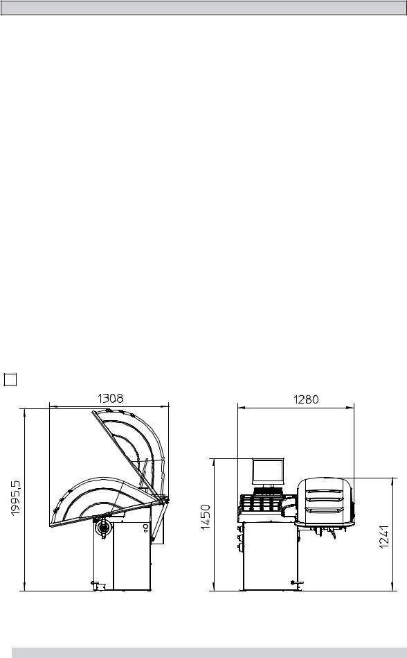
► 1.3 - Overall dimensions (42" guard)
1
I 0567 GB- 3

► 1.4 - Specification
Single phase power supply |
115 - 230 V 50-60 Hz |
Protection class |
IP 54 |
Max. power consumption |
1,1 Kw |
Monitor |
SVGA 15" |
Balancing speed approx. |
180 min-1 |
Cycle time for average wheel (14 Kg) |
6 seconds |
Balancing accuracy |
0,5 grams |
Position resolution |
± 1.4 ° |
Average noise level |
< 70 dB(A) |
Distance rim - machine |
0 - 280 mm (400 mm can be preset) |
Rim width setting range |
1.5" ÷ 20" or 40 ÷ 510 mm |
Diameter setting range |
10" ÷ 30" or 265 ÷ 765 mm |
Total wheel diameter within guard |
1067mm (42") |
Total wheel width within guard |
500 mm (42") |
Min/max. compressed air pressure |
7 ÷ 10 Kg/cm2 |
|
approx. 0.7 to 1 Mpa; |
|
approx. 7 to 10 BAR; |
|
approx. 100 to 145 PSI. |
2 - HANDLING AND LIFTING
N.B.: DO NOT HOIST THE WHEEL BALANCER USING DIFFERENT GRIPS.
2 |
2a |
I 0567 GB- 4

3 - COMMISSIONING
► 3.1 - Anchoring
The machine can be operated on any flat non-resilient floor.
Make sure that the machine rests solely on the three support points provided (fig. 2a).
If possible, it is advisable to anchor to the floor using relative mounting feet (see fig. 2a) in the event of continual use with wheels weighing over 35 Kg.
► 3.2 - Electrical connection
The machine is supplied with a single phase mains cable plus earth (ground).
The supply voltage (and mains frequency) is given on the machine nameplate. It may NOT be changed. Connection to the mains should always be made by expert personnel.
The machine should not be started up without proper earth (ground) connection.
Connection to the mains should be through a slow acting safety switch rated at 4A amp (230V) or 10 amp (115V) .
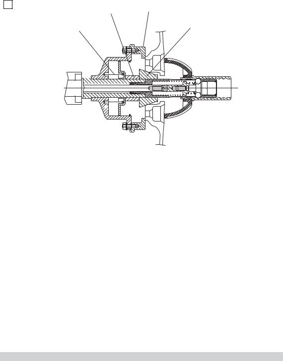
► 3.3 - Adapter mounting
The balancing machine is supplied complete with cone adapter for fastening wheels with central bore. Other optional flanges can be mounted once the terminal part is removed (also see enclosed brochures)
N.B. : CAREFULLY CLEAN THE COUPLING SURFACES BEFORE PERFORMING ANY
OPERATION.
DISMOUNTING THREADED END PIECE
3
A
B
a)Back-off screw B and remove threaded end-piece A.
b)Fit the new adapter.
I 0567 GB- 5
► 3.4 - Guard mounting and adjustment
a) Fasten the components to the base as illustrated in specific exploded view.
b) The position of the wheel guard when closed can be adjusted with relative screw accessible at the back. Correct position is shown in Fig. 1.
c) Check that the microswitch is held down when the guard is closed. d) Adjust the angular position of microswitch control.
► 3.5 - Spacer WD
When balancing very wide wheels (9”), there is not enough space to turn the distance gauge. To withdraw the wheel from the machine side, fit spacer WD on the adapter body and secure it with the standard issue nuts. When centring the wheel with the cone on the inside, fit the other cone as a spacer to obtain spring thrust.
4 |
|
|
|
DC |
WD |
||||||
|
|
|
|
|
|
|
|
|
|
||
|
Spring |
|
|
|
|
|
Cone |
||||
|
|
|
|
|
|
|
|
|
|
||
|
|
|
|
|
|
|
|
|
|
|
|
|
|
|
|
|
|
|
|
|
|
|
|
|
|
|
|
|
|
|
|
|
|
|
|
|
|
|
|
|
|
|
|
|
|
|
|
|
|
|
|
|
|
|
|
|
|
|
|
|
|
|
|
|
|
|
|
|
|
|
|
|
|
|
|
|
|
|
|
|
|
|
|
|
|
|
|
|
|
|
|
|
|
|
|
I 0567 GB- 6
4 - CONTROLS AND COMPONENTS
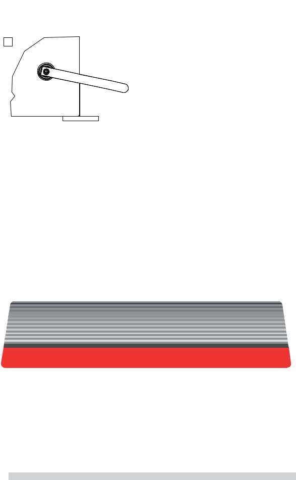
► 4.1 - Brake pedal
5
This pedal allows the operator to hold the wheel when fitting the counterweights. It must not be actuated during the measuring cycle.
► 4.2 - Automatic distance and diameter gauge
This gauge allows measurement of the distance of the wheel from the machine and the wheel diameter at the point of application of the counterweight. It also allows correct positioning of the counterweights on the inside rim by using the specific function (see INDICATION OF EXACT CORRECTION WEIGHT POSITION ) which allows reading, on the monitor, the position used for the measurement within the rim (for calibration, see the corresponding section).
► 4.3 - Automatic width gauge (optional)
Width gauging is through a SONAR device which measures the distance of the wheel without mechanical contact, merely by closing the guard and each time a valid measurement has been made with gauge AUTOMATIC DISTANCE AND DIAMETER GAUGE.
► 4.4 - Automatic wheel positioning
At the end of the spin, the wheel is positioned according to the unbalance on the outside or else according to the static unbalance (when selected).
Accuracy is ± 20 degrees.
► 4.5 - Keyboard
FUNCTION KEYS: they directly select the function on screen
Confirm |
Starts measuring |
Stops machine |
Selection of special |
cycle |
cycle |
function |
|
|
N.B.: Press the buttons with the fingers only: never use the counterweight pincers or other pointed objects.
When the beep signal is enabled (see section ACOUSTIC SIGNAL), pressing of any push button is accompanied by a “beep”.
The TFT monitor is NOT a TOUCH SCREEN type.
I 0567 GB- 7

5 - INDICATIONS AND USE OF THE WHEEL BALANCER
The monitor shows several information and suggests various alternative ways of use to the operator. This is through various “screens”.
► 5.1 - Initial screen
Buttons enabled:
: main functions screen (see MENU ACCESS DIAGRAM)
: selecting static correction

 : balancing spin (see RESULT OF MEASUREMENT)
Dimensions gauge: when extracted, the Dimensions screen is selected (see PRESETTING OF WHEEL
DIMENSIONS).
If the machine remains on the initial screen for a certain amount of time without being used, the system is automatically switched to a screen-save. Striking of any key, movement of the wheel of distance + diameter gauge will cause automatic switching from the screen-save menu to the initial screen.
► 5.1.1 - Screen-save screen
Name of the wheel balancer’s owner. Can be preset via the monitor.
I 0567 GB- 8

► 5.2 - Menu access diagram
N.B. : - The symbol

 indicates the presence of a further menu.
-To return to the previous menu, press button 
-To return to the initial screen, press button 

 A
A
User control
B
H
C |
PASSWORD : |
+ |
+ |
+ |
FOR SPECIALIZED PERSONNEL ONLY |
||||
 D
D
User
E
F
I 0567 GB- 9

►5.3 - Presetting of wheel dimensions
►5.3.1 - Automatic presetting (see also CORRECTION MODE)
INDICATOR
L.T. function enabled (see Buttons Enabled)
INDICATOR: Width Sonar function enabled
► 5.3.1.1 - Standard wheels
The screen appears upon removing the distance + diameter gauge.
The “dimension acquired” message is indicated by the correction weight symbol, which changes from blue to red. - INNER SIDE WEIGHT: Using the special grip, move the end of the gauge against the rim in position:
a) Sprung weight : in one of the positions A/B indicated in figure 8.
8 |
Pos A |
Pos B
b) Adhesive weight: in the position indicated below
8a |
Position of adhesive |
|
weight |
|
FI
Note: Always use the round part of the striker plate.
Hold the gauge in position for at least 2 seconds.
If the acoustic signal is enabled (see ACOUSTIC SIGNAL), the acquisition of the dimensions is accompanied by a “beep”.
I 0567 GB- 10
 Loading...