


|
Operating instructions |
I |
|
Contents |
page |
|
|
1- GENERAL ................................................................................................................................................................................. |
|
3 |
|
1.1 |
- GENERAL SAFETY RECOMMENDATIONS ........................................................................................................... |
|
3 |
1.1.1 - STANDARD SAFETY DEVICES ........................................................................................................................... |
|
3 |
|
1.2 |
- FIELD OF APPLICATION ......................................................................................................................................... |
|
3 |
1.3 |
- OVERALL DIMENSIONS ......................................................................................................................................... |
|
3 |
1.4 |
- SPECIFICATION ...................................................................................................................................................... |
|
4 |
2 - HANDLING AND HOISTING ................................................................................................................................................... |
|
4 |
|
3 - COMMISSIONING ................................................................................................................................................................... |
|
5 |
|
3.1 |
- ANCHORING ............................................................................................................................................................ |
|
5 |
3.2 |
- ELECTRICAL CONNECTION .................................................................................................................................. |
|
5 |
3.3 |
- PNEUMATIC CONNECTION (Versions SE and/or dispenser) ................................................................................. |
|
5 |
3.4 |
- TO REPLACE THE ROLL OF LEAD ........................................................................................................................ |
|
5 |
3.5 |
- EXTRA SAFETY DEVICES (VERSION SE) ............................................................................................................. |
|
6 |
3.6 |
- ADAPTER MOUNTING ............................................................................................................................................ |
|
6 |
3.7 |
- GUARD MOUNTING AND ADJUSTMENT (Exploded drawing 4) ............................................................................ |
|
6 |
3.8 |
- SPACER WD .............................................................................................................................................................. |
|
6 |
4 - CONTROLS AND COMPONENTS .......................................................................................................................................... |
|
7 |
|
4.1 |
- BRAKE PEDAL ......................................................................................................................................................... |
|
7 |
4.2 |
- PNEUMATIC LOCKING PEDAL (Version SE) .......................................................................................................... |
|
7 |
4.3 |
- AUTOMATIC DISTANCE AND DIAMETER GAUGE ................................................................................... |
............. |
7 |
4.4 |
- AUTOMATIC WIDTH GAUGE .................................................................................................................................. |
|
7 |
4.5 |
- COUNTERWEIGHT DISPENSER (OPTIONAL) ....................................................................................................... |
|
7 |
4.6 |
- AUTOMATIC WHEEL POSITIONING......................................................................................................................... |
|
7 |
4.7 |
- CLOCK CONTROL.................................................................................................................................................... |
|
7 |
4.8 |
- KEYBOARD............................................................................................................................................................... |
|
8 |
5 - INDICATIONS AND USE OF THE WHEEL BALANCER ........................................................................................................ |
|
9 |
|
5.1 |
- INITIAL SCREEN ..................................................................................................................................................... |
|
9 |
5.1.2 SCREEN-SAVE SCREEN ....................................................................................................................................... |
|
9 |
|
5.2 |
- MENU ACCESS DIAGRAM ................................................................................................................................... |
|
10 |
5.3 |
- PRESETTING OF WHEEL DIMENSIONS .............................................................................................................. |
|
11 |
5.3.1 AUTOMATIC PRESETTING ................................................................................................................................... |
|
11 |
|
5.3.2 TO CALL MEMORIZED MEASUREMENTS .......................................................................................................... |
|
12 |
|
5.3.3 - MANUAL PRESETTING ...................................................................................................................................... |
|
13 |
|
5.3.4 - PRESETTING FOR LARGE-SCALE PRODUCTION............................................................................................ |
|
15 |
|
5.4 |
- USER CONTROL ................................................................................................................................................... |
|
15 |
5.4.1 - USER MEMORIZATION ...................................................................................................................................... |
|
15 |
|
5.4.2 - TO CALL USER ................................................................................................................................................... |
|
15 |
|
5.5 |
- RESULT OF MEASUREMENT ............................................................................................................................... |
|
16 |
5.5.1 - INDICATION OF EXACT CORRECTION WEIGHT POSITION ......................................................................... |
|
17 |
|
5.5.2 - “SPLIT” CONTROL .............................................................................................................................................. |
|
18 |
|
5.5.3 - UNBALANCE OPTIMIZATION ............................................................................................................................ |
|
19 |
|
5.5.4 - ALU AND STATIC MODES .................................................................................................................................. |
|
19 |
|
5.5.5 - TO CANCEL STATIC UNBALANCE .................................................................................................................... |
|
20 |
|
5.6 |
- STATISTICS ............................................................................................................................................................. |
|
20 |
5.7 |
- DISPENSER ........................................................................................................................................................... |
|
21 |
5.8 |
- WHEN AND WHY MATCHING ................................................................................................................................. |
|
21 |
5.9 |
- ECCENTRICITY MEASUREMENT (OPTIONAL) ..................................................................................... |
.............. |
23 |
6 - SETUP |
................................................................................................................................................................................... |
|
25 |
6.1 |
- LANGUAGE ............................................................................................................................................................ |
|
25 |
6.2 |
- UNIT OF UNBALANCE MEASUREMENT ............................................................................................................. |
|
25 |
6.3 |
- UNBALANCE DISPLAY THRESHOLD ................................................................................................................... |
|
25 |
6.4 |
- UNBALANCE DISPLAY PITCH .............................................................................................................................. |
|
25 |
6.5 |
- SPIN WITH GUARD CLOSED ............................................................................................................................... |
|
25 |
6.6 |
- SCREEN-SAVER TIME .......................................................................................................................................... |
|
25 |
6.7 |
- VISUAL ECCENTRICITY CHECK .......................................................................................................................... |
|
25 |
6.8 |
- ACUSTIC SIGNAL.................................................................................................................................................... |
|
25 |
6.9 |
- CLOCK SET-UP ....................................................................................................................................................... |
|
25 |
6.10 - FIRST HARMONIC LIMIT ...................................................................................................................................... |
|
25 |
|
7 - SPECIAL CALIBRATIONS AND FUNCTIONS ..................................................................................................................... |
|
26 |
|
7.1 |
- ENABLING OF WIDTH MEASUREMENT .............................................................................................................. |
|
26 |
7.2 |
- ENABLING OF THE DISPENSER ......................................................................................................................... |
|
26 |
7.3 |
- PRESETTING THE CUSTOMER AND USER NAME .............................................................................................. |
|
26 |
7.4 |
- ENABLING OF ECCENTRICITY MEASUREMENT................................................................................................ |
|
26 |
7.5 |
- DRAWER UNIT ........................................................................................................................................................ |
|
26 |
7.6 |
- CALIBRATIONS........................................................................................................................................................ |
|
26 |
7.6.1 - GAUGE CALIBRATION ......................................................................................................................................... |
|
26 |
|
7.6.2 - DISPENSER CONSTANTS ................................................................................................................................... |
|
27 |
|
7.6.2.1 - DISPENSER CALIBRATION .............................................................................................................................. |
|
27 |
|
7.6.2.2 - NUMBER OF DISPENSER PULSES IN ADVANCE........................................................................................... |
|
27 |
|
7.6.3 - ADAPTER ECCENTRICITY CORRECTION ......................................................................................................... |
|
27 |
|
7.6.4 - WHEEL BALANCER CALIBRATION ..................................................................................................................... |
|
27 |
|
I 0201 GB- 1
7.6.5 - TEST DRAWER UNIT ........................................................................................................................................... |
27 |
7.6.6 - SELF TEST BALANCING MACHINE .................................................................................................................... |
27 |
7.6.6.1 - TO CHECK THE ENCODER .............................................................................................................................. |
28 |
7.7 - SETUP NAMES....................................................................................................................................................... |
28 |
8 - ERRORS ................................................................................................................................................................................ |
29 |
9 - ROUTINE MAINTENANCE .................................................................................................................................................... |
30 |
9.1 - SCHEDULE MAINTENANCE................................................................................................................................... |
30 |
9.2 - TO REPLACE THE FUSES .................................................................................................................................... |
30 |
9.3 - ADAPTER END PIECE, SPINDLE P........................................................................................................................ |
30 |
10 - RECOMMENDED SPARE PARTS LIST ............................................................................................................................. |
31 |
I 0201 GB - 2
1- GENERAL
1.1 - GENERAL SAFETY RECOMMENDATIONS
-The balancing machine should only be used by duly authorized and trained personnel.
-The balancing machine should not be used for purposes other than those described in the instruction manual.
-Under no way should the balancing machine be modified except for those modifications made explicitly by the manufacturer.
-Never remove the safety devices. Any work on the machine should only be carried out by duly authorized specialist personnel.
-Do not use strong jets of compressed air for cleaning.
-Use alcohol to clean plastic panels or shelves (AVOID LIQUIDS CONTAINING SOLVENTS).
-Before starting the wheel balancing cycle, make sure that the wheel is securely locked on the adapter.
-The machine operator should not wear clothes with flapping edges. Make sure that unauthorized personnel do not approach the balancing machine during the work cycle.
-Avoid placing counterweights or other objects in the base which could impair the correct operation of the balancing machine.
1.1.1 - STANDARD SAFETY DEVICES
-STOP push button for stopping the wheel under emergency conditions.
-The safety guard of high impact plastic is with shape and size designed to prevent risk of counterweights from flying out in any direction except towards the floor.
-A microswitch prevents starting the machine if the guard is not lowered and stops the wheel whenever the guard is raised.
1.2 - FIELD OF APPLICATION
The machine is designed for balancing car or motorcycle wheels weighing less than 65 kg. It can be operated within a temperature range of 0° to +45°C.
It is provided with an automatic adhesive counterweight dispenser (optional). It can measure the geometric radial run-out of the wheels (optional)
Fitted with two laser indicators for the correction position.
Can be fi tted with a weight-holder drawer unit with luminous indicators of the weight to be used (optional)
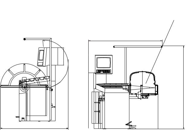
1.3 - OVERALL DIMENSIONS (Standard protection)
Fig. 1
1385 |
1505 |
1695 |
I 0201 GB- 3 |

1.4 - SPECIFICATION
Single phase power supply.............................. |
115 - 230 V 50-60 Hz |
Protection class ............................................... |
IP 54 |
Max. power consumption................................. |
1100 W |
Monitor ............................................................ |
SVGA 15" |
Balancing speed approx. ................................. |
180 min-1 |
Cycle time for average wheel (14 Kg) .......... |
5 seconds |
Balancing accuracy ......................................... |
0,5 grams |
Position resolution ........................................... |
± 1.4 ° |
Average noise level ......................................... |
< 70 dB(A) |
Distance rim - machine.................................... |
0 - 250 mm (400 mm can be preset) |
Larghezza cerchione impostabile ................... |
1.5" ÷ 20" or 40 ÷ 510 mm |
Diameter setting range .................................... |
10" ÷ 24" or 265 ÷ 615 mm |
Total wheel diameter within guard ................... |
870 mm (standard) |
Total wheel width within guard......................... |
430 mm (standard) |
Max. wheel weight ........................................... |
65 Kg. |
Min/max. compressed air pressure ................. |
7 ÷ 10 Kg/cm2 |
......................................................................... |
approx. 0.7 ÷ 1 Mpa; |
......................................................................... |
approx. 7 ÷ 10 BAR; |
......................................................................... |
approx. 100 ÷ 145 PSI. |
2 - HANDLING AND HOISTING
N.B. DO NOT HOIST THE MACHINE BY LEVERING UNDER THE CABINET
Fig. 2 |
Fig. 2 A |
I 0201 GB - 4

3 - COMMISSIONING
3.1 - ANCHORING
The machine can be operated on any fl at non-resilient fl oor.
Make sure that the machine rests solely on the three support points provided (fi g. 2a).
If possible, it is advisable to anchor to the fl oor using relative mounting feet (see fi g. 2a) in the event of continual use with wheels weighing over 35 Kg.
3.2 - ELECTRICAL CONNECTION
The machine is supplied with a single phase mains cable plus earth (ground).
The supply voltage (and mains frequency) is given on the machine nameplate. It may NOT be changed. Connection to the mains should always be made by expert personnel.
The machine should not be started up without proper earth (ground) connection.
Connection to the mains should be through a slow acting safety switch rated at 4A amp (230V) or 10 amp (115V) .
3.3 - PNEUMATIC CONNECTION
For operation of the spindle with pneumatic locking (constant thrust air spring) connect the balancing machine to the compressed air main. The connection fi tting is located at the back of the machine. A pressure of at least 7 kg/cm2 (approx. 0.7 MPa or 7 BAR or 100 PSI) is required for correction operation of the release device.
3.4 - TO REPLACE THE ROLL OF LEAD
(for machines provided with the dispenser option) a) Open the cabinet door.
b) Mount the roll and insert the strip of lead under the rubber covered wheel; for easier insertion, act on pin (1).
c) Close the cabinet.
d) Press the push buttons to dispense a counterweight with relative cutting.
N.B. - Mount the roll of lead correctly on the spool (2)
-Never carry out point d) with the cabinet open.
-When the roll of lead is close to finishing (last 2-3 rounds of strip), lift the lead from the spool to decrease its curvature.
-Avoid bending the lead strip: the presence of strong bends and counterbends would impair correct operation of the feed system.
-If the dispenser is not used for a long period, it could be possible that the first weight to
be distributed is not accurate, therefore it should be discarded.
Fig. 3
1
2
I 0201 GB- 5
3.5 - EXTRA SAFETY DEVICES
- Wheel always locked even when there is pressure failure during the balancing cycle.
- Rotary block wheel retainer which, in the event of accidental pressing of the pneumatic locking pedal during the balancing cycle, avoids risk of the wheel slipping from the adapter.
- Always actuate the unlocking control pedal with the machine stationary in order to avoid stress and abnormal wear on the adapter.
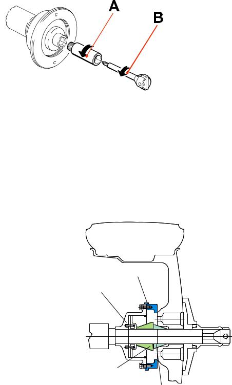
3.6 - ADAPTER MOUNTING
The balancing machine is supplied complete with cone adapter for fastening wheels with central bore. Other optional adapters can be mounted; hardened shaft and tapers.
Fig. 4 Fig. 4
C68 Professional |
a) Unscrew rod B. |
|
b) Unscrew end-piece A. |
|
c) Fit the new adapter. |
N.B. If there is no pressure, to remove the wheel, merely unscrew rod B to its full extent.
3.7 - GUARD MOUNTING AND ADJUSTMENT
a)Fasten the components to the base as illustrated in specifi c exploded view.
b)The position of the wheel guard when closed can be adjusted with relative screw accessible at the back. Correct position is the one which keeps the tube exactly horizontal with wheel guard closed.
c)Check that the microswitch is held down when the guard is closed.
d)Adjust the angular position of microswitch control.
3.8 - SPACER WD
When balancing very wide wheels (9”), there is |
|
not enough space to turn the distance gauge. |
|
To withdraw the wheel from the machine side, |
SPACER WD |
fi t spacer WD on the adapter body and secure |
|
it with the standard issue nuts. When centring |
Spring |
the wheel with the cone on the inside, fi t the |
|
other cone as a spacer to obtain spring thrust. |
|
Spacer joint
Centring Joint
I 0201 GB - 6

4 - CONTROLS AND COMPONENTS
4.1 - BRAKE PEDAL
This pedal allows the operator to hold the wheel when fi tting the counterweights. It must not be actuated during the measuring cycle.
4.2 - PNEUMATIC LOCKING PEDAL
This pedal allows releasing the device fastening the wheel on the adapter. Do not actuate this pedal during the machine cycle and/or when adapters other than the standard cone adapter are mounted.
The pedal has a stable position; UP to clamp the wheel, held DOWN to release it.
4.3 - AUTOMATIC DISTANCE AND DIAMETER GAUGE
This gauge allows measurement of the distance of the wheel from the machine and the wheel diameter at the point of application of the counterweight.
It also allows correct positioning of the counterweights on the inside rim by using the specifi c function (see Indication of exact correction weight position ) which allows reading, on the monitor, the position used for the measurement within the rim (For calibration, see Calibration).
The gauge can only be used with the counterweight pincers mounted.
4.4 - AUTOMATIC WIDTH GAUGE (Option)
Width gauging is through a SONAR device which measures the distance of the wheel without mechanical contact, merely by closing the guard and each time a valid measurement has been made with gauge 4.3.
4.5 - COUNTERWEIGHT DISPENSER (Option)
The dispenser consists of a mechanism, controlled by the measuring instruments, designed to distribute a counterweight equivalent to the measured weight, thus avoiding the approximations of commercial counterweights. The counterweight is cut to the exact weight even if the approximate weight appears on the displays. Accuracy of the weight is ± 1 gram. To dispense the counterweight, press relative function push button for each side. The dispenser is operated pneumatically and uses the max. inlet pressure which should be at least 7 kg/cm2 .
4.6 - AUTOMATIC WHEEL POSITIONING
At the end of the spin, the wheel is positioned according to the unbalance on the outside or else according to the static unbalance (when selected).
Accuracy is ± 20 degrees.
4.7 - CLOCK CONTROL
The wheel balancer is provided with a clock having a back-up of about one month with the machine switched off. If the machine remains off for a long period, at the fi rst switch on, check the date and time
(see Clock set-up), adjusting them if necessary.
I 0201 GB- 7

4.8 - KEYBOARD
FUNCTION KEYS: they immediately select corresponding function
Stops measuring cycle
Selection of special functions
Confirm
Starts measuring cycle
N.B. - Press the buttons with the fingers only: never use the counterweight pincers or other pointed objects.
- When the beep signal is enabled (see section ACUSTIC SIGNAL), pressing of any push button is accompanied by a “beep”.
I 0201 GB - 8
5 - INDICATIONS AND USE OF THE WHEEL BALANCER
The monitor shows several information and suggests various alternative ways of use to the operator. This is through various “screens”.
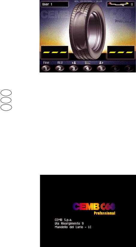
5.1 - INITIAL SCREEN
Buttons enabled
MENU' |
: main functions screen (see MENU ACCESS DIAGRAM) |
2 |
: type of correction (see ALU AND STATIC MODES) |
START |
: balancing spin (see RESULT OF MEASUREMENT ) |
Dimensions gauge: when extracted, the Dimensions screen is selected (see PRESETTING OF WHEEL
DIMENSIONS) .
If the machine remains on the initial screen for a certain amount of time without being used, the system is automatically switched to a screen-save. Striking of any key, movement of the wheel of distance +
diameter gauge will cause automatic switching from the screen-save menu to the initial screen.
5.1.2 SCREEN-SAVE SCREEN
N.B. Name of the wheel balancer’s owner. Can be preset via the monitor (see Section ENABLING OF
ECCENTRICITY MEASUREMENT)
CEMB S.p.A.
Via Risorgimento 9
Mandello Lario - LC
I 0201 GB- 9

5.2 - MENU ACCESS DIAGRAM
N.B. |
- The symbol |
indicates the presence of a further menu. |
- To return to the previous menu, press button STOP
- To return to the initial screen, press button MENU'
Machine setup parameters
Language
Unit of unbalance measurement
Unbalance display threshold
Unbalance display pitch
H Spin with guard closing
Screen-saver time
Next
Cancel
Machine setup parameters
Visual eccentricity control
Acoustic Signal
Clock Setting
First harmonic limit
Previous
Cancel
Names Setup
Client Generalities
Names of Users
Cancel
Calibrations
Distance
Diameter
Width
MENU' |
A |
|
|
|
|
|
|
|
|
||||
|
|
|
|
|
|
|
|
|
|
|
|
||
User control |
|
Call user |
|
|
|
||||||||
|
Save user |
|
|
|
|||||||||
(5.4) |
|
|
|
|
|
|
|
|
|
||||
|
|
|
|
|
|
|
|
|
|
|
|
|
|
|
|
|
|
|
|
|
Optimization |
|
|
|
|||
|
|
|
|
|
|
|
Dimensions |
|
|
|
|||
B |
|
|
|
|
|
Statistic |
|
|
|
||||
|
|
|
|
|
Set-up |
|
|
|
|||||
|
|
|
|
|
|
|
Special functions |
|
|
|
|||
|
|
|
|
|
|
||||||||
|
|
|
|
Cancel |
|||||||||
|
|
|
|
|
|
|
|
|
|
|
|
|
|
|
|
|
PASSWORD : |
1 + 3 + 5 + 7 |
|
|
|||||||
|
|
CFor specialized personnel only |
|||||||||||
|
|
|
|
|
|
|
|
|
|
|
|||
|
|
|
|
|
|
|
|
|
|
Special functions |
|
||
|
|
|
D |
||||||||||
|
|
|
|
|
|
|
|
|
|
|
|||
|
|
|
|
|
|
Width measurement |
|
|
|||||
|
|
selections |
|
|
|
Adhesive weight dispenser |
|
|
|||||
|
|
|
|
|
|
|
|
|
Eccentricity measurement |
|
|
||
|
|
|
|
|
|
|
|
|
Customer’s personal |
|
|
||
User control |
|
|
|
Users’ names |
|
|
|||||||
|
|
|
|
|
|
|
|
|
Calibration |
|
|
||
|
|
|
|
|
|
|
|
|
|
|
|
|
|
Cancel
E
Calibrations
Potentiometer
Adhesive weight dispenser
Eccentricity correction
Wheel balancer self-cali- bration
Wheel balancer self test
Cancel
F G
Adhesive weight dispenser
Reference weight
n° of pulses in advance
Lenght of reference weight
Emission of reference weight
Cancel |
|
Cancel |
I 0201 GB - 10
 Loading...