

Page 1

ENGLISH
GB
Use and maintenance manual
General Index
1. FOREWORD 3
1.1 GENERAL 3
1.2 PURPOSE OF THE MANUAL 3
1.3 WHERE AND HOW TO KEEP THE MANUAL 3
1.4 MANUAL UPGRADES 3
1.5 COLLABORATION WITH USERS 4
1.6 MANUFACTURER 4
1.7 MANUFACTURER'S RESPONSIBILITY AND WARRANTY 4
1.7.1 Terms of warranty 4
1.8 TECHNICAL ASSISTANCE SERVICE 5
1.9 COPYRIGHT 5
2. MACHINE DESCRIPTION 6
2.1 PURPOSE 6
2.2 TECHNICAL SPECIFICATIONS 6
2.3 DIMENSIONS 6
3. STARTING 7
4. CONTROL PANEL 8
5 USE OF THE WHEEL BALANCER 9
5.1 PRESETTING OF WHEEL DIMENSIONS 9
5.1.1 AWA 9
5.1.2 Modifying set dimensions 10
5.1.2.1 Standard correction method 10
5.1.2.2 Correction method with adhesive weights (ALU) 10
5.1.3 Static & combined modes 10
5.2 MEASUREMENT RESULT 11
5.3 EXACT POSITIONING OF THE ADHESIVE WEIGHT BY MEANS OF THE GAUGE WITH CLIPS 11
5.4 SPLIT FUNCTION (UNBALANCE RESOLUTION) 11
5.5 AUTOMATIC MINIMIZATION OF STATIC UNBALANCE 12
6. SETUP 13
6.1 MENU 13
6.2 UNBALANCE OPTIMISATION 14
6.3 SELF-DIAGNOSTICS 14
6.4 CALIBRATION 14
6.5 AUTOMATIC GAUGES CALIBRATION 15
6.5.1 Rim distance gauge 15
6.5.2 Diameter gauge 16
7. DIAGNOSTICS 17
I 1053 - 09/13 - Ver. 00
Page 2

7.1 INCONSISTENT UNBALANCE READINGS 17
7.2 ALARM SIGNAL 17
8. MAINTENANCE 20
8.1 GENERAL 20
8.1.1 Introductory notes 20
8.1.2 Safety rules 20
8.1.3 Replacing fuses 20
9. DISPOSAL 21
9.1 DISPOSING OF THE BALANCER 21
9.2 DISPOSING OF ELECTRONICS COMPONENTS 21
10. SPARE PARTS 21
10.1 IDENTIFICATION AND ORDERING METHOD 21
11. ATTACHED DOCUMENTATION 21
Page 3

Use and maintenance manual Rev. 09-2013
1. Foreword
WARNING
ThI s m ANu Al Is AN IN TeG RAl pART o f T he INsTAllATIoN
mAN uAl WhIc h shoul d be coNsulTe d coNce RNIN G sTARTIN G
ANd usI NG The mAc hIN e sA fely.
ReA d cA Ref ully b efo Re c oNT INuI NG.
1.1 GENERAL
The machine has been constructed in conformity with the
current EC Directives and the technical standards implementing the requirements, as stated in the declaration
of conformity issued by the manufacturer and attached
to the manual.
This publication, hereinafter simply referred to as ‘man-
ual’, contains all the information required to safely use
and service the machine referred to in the Declaration of
Conformity.
This appliance, hereinafter is generically referred to as
‘machine’.
The manual addresses operators instructed on the precautions to take in relation to the presence of electric current
and moving devices.
This publication is intended for all ‘users’ who as far as
within their competence need to and/or are obliged to
give instructions to others or operate on the machine
themselves.
These persons can be identified as follows:
- operators directly involved in transporting, storing,
installing, using and servicing the machine from when
it is put on the market until when it is scrapped;
- direct private users.
The original Italian text of this publication constitutes the
only reference to resolve any interpretation controversies
related to the translation into the European Community
languages.
This publication forms an integral part of the machine
and must therefore be kept for future reference until final
dismantling and scrapping of the machine.
ENGLISH
1.2 PURPOSE OF THE MANUAL
This manual, and the installation manual, contains the
instructions required to use the machine safely and carry
out routine maintenance work.
Any calibrations, adjustments and extraordinary maintenance operations are not considered in this document as
they may only be performed by the service engineer who
must work on the machine according to the technical and
rated characteristics for which it was built.
Though it is fundamental to read this manual, it cannot
replace skilled technical staff who must be adequately
trained beforehand.
The foreseen use and configurations of the machine are
the only ones allowed by the manufacturer; do not attempt
to use the machine in a different way.
Any other use or configuration must be agreed in advance
with the manufacturer in writing and in this case an annex
will be attached to this manual.
For use, the user must also comply with the specific
workplace legislation in force in the country where the
machine is installed.
The manual also refers to laws, directives, etc., that the
user must know and consult in order to accomplish the
goals that the manual sets out to achieve.
1.3 WHERE AND HOW TO KEEP THE
MANUAL
This manual (and relative attachments) must be kept in
a safe and dry place and must always be available for
consultation.
Make a copy and keep it in the archive.
When exchanging information with the manufacturer or
the technical assistance staff authorised by the former,
quote the rating plate information and the serial number
of the machine.
This manual must be kept for the entire lifetime of the
machine, and if necessary (e.g.: damage making all or
some of it illegible, etc.) the user must request another
copy exclusively from the manufacturer, quoting the publication code indicated on the cover.
Introduction
1.4 MANUAL UPGRADES
This manual is an integral part of the machine and reflects
the state of the art at the moment it was put on the market.
The publication complies with the directives in force on
that date; the manual cannot be considered inadequate
3
Page 4
Use and maintenance manual Rev. 09-2013
as a result of regulatory updates or modifications to the
machine.
Any manual upgrades that the manufacturer may see fit to
send to users will become an integral part of the manual
ENGLISH
and must be kept together with it.
1.5 COLLABORATION WITH USERS
The manufacturer will be pleased to provide its customers with any further information they may require and will
consider proposals for improving this manual in order to
more fully satisfy the requirements it was written for.
In case of transfer of ownership of the machine,
which must always be accompanied by the use and
maintenance manual, the original user must inform
the manufacturer of the name and address of the
new user in order to allow it to send the new user
any communications and/or updates deemed to be
indispensable.
This publication is the property of the Manufacturer
and may not be fully or partly reproduced without prior
written agreement.
in this manual
- use of the machine by people who have not read and
fully understood the contents of this manual;
- use in breach of specific regulations in force in the
country of installation;
- modifications made to the machine, software and operating logic, unless authorised by the manufacturer
in writing;
- unauthorised repairs;
- exceptional events.
Transfer of the machine to a third party must also include
this manual; failure to include the manual automatically
invalidates all the rights of the purchaser, including the
terms of warranty, where applicable.
If the machine is transferred to a third party in a country with
a different language from the one written in this manual,
the original user shall provide a faithful translation of this
manual in the language of country in which the machine
will operate.
1.7.1 Terms of warranty
The Manufacturer guarantees the machines it manufacturers against all manufacturing or assembly faults for 12
(twelve) months from the date of collection or delivery.
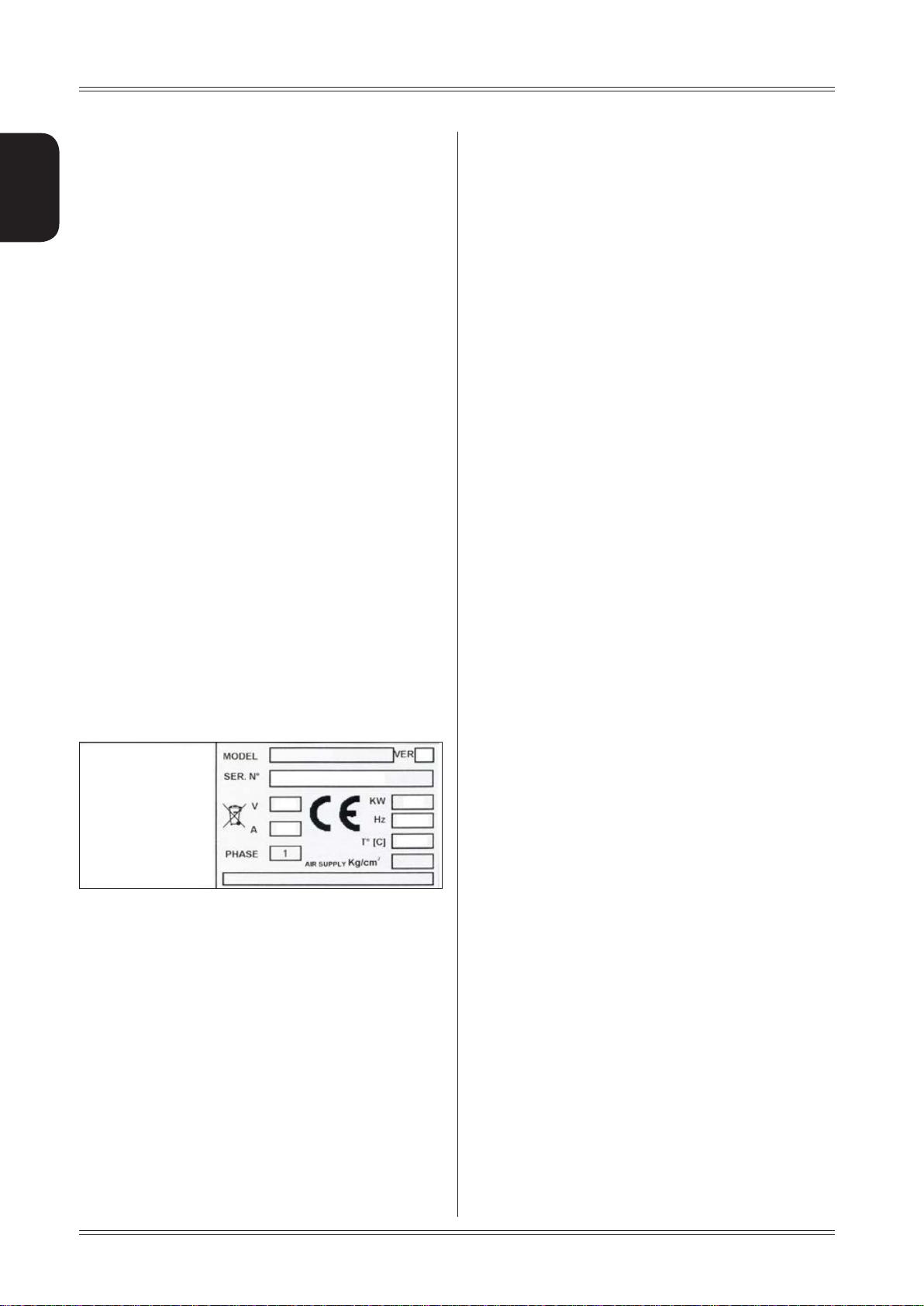
1.6 MANUFACTURER
The machine identification data is indicated on the plate
mounted on the machine.
The plate below is shown for the sake of example.
1.7 MANUFACTURER'S RESPONSIBILITY
AND WARRANTY
In order to make use of the manufacturer's warranty, the
user must scrupulously observe the precautions contained
in the manual, in particular he must:
- never exceed the limits of use of the machine;
- always constantly and carefully clean and service the
machine;
- have the machine used by people of proven capacity
and attitude, adequately trained for the purpose.
The manufacturer declines all direct and indirect liability
caused by:
- use of the machine in a different way from that indicated
The Manufacturer undertakes to replace or repair any part
which it deems to be faulty free of charge at its factory,
carriage paid.
If a Manufacturer's repairman (or a person authorised by
the same) is required to work at the user's facilities, the
relative travel expenses and board and lodging shall be
charged to the user.
The free supply of parts under warranty is always subject
to the faulty part being inspected by the manufacturer (or
a person authorised by the same).
The warranty is not extended following repairs or other
work done to the machine.
The warranty does not cover damage to the machine
deriving from:
- transport;
- neglect;
- improper use and/or use not in compliance with the
instructions in the operating manual
- incorrect electrical connections.
The warranty is invalidated in case of:
- repairs made by people who were not authorised by
the manufacturer;
- modifications that were not authorised by the manufacturer;
- use of parts and/or equipment that were not supplied
or approved by the manufacturer;
- removal or alteration of the machine identification
plate.
4
Introduction
Page 5

Use and maintenance manual Rev. 09-2013
1.8 TECHNICAL ASSISTANCE SERVICE
For any technical service operation, contact the manufacturer
directly or an authorised dealer always quoting the model,
the version and the serial number of the machine.
1.9 COPYRIGHT
The information contained in this manual may not be
disclosed to third parties. Partial or total duplication, unless authorised by the Manufacturer in writing, through
photocopying, duplication or other systems, including
electronic acquisition, is breach of copyright and can lead
to prosecution.
ENGLISH
Introduction
5
Page 6
2. Machine description
ENGLISH
Use and maintenance manual Rev. 09-2013
2.1 PURPOSE
It is used to balance the wheels of cars, vans, 4-WD, motorcycles and scooters. The wheels must weigh less than
75 kg. and, when fitted on the balancing machine, must
not interfere with any fixed part of the machine, excluding
the shaft and support adaptor. It can be operated in the
temperature range of 0° to + 45°C.
The machine is supplied with equipment enabling the
vast majority of car wheels available on the market to be
fitted. Other wheels with special dimensions, geometry
and centring require special adaptors supplied on request.
The machine can operate only on at non resilient oor.
To lift the machine, lever only on the base where the 3
support points are located. never, under any circustance,
apply force to other points such as the spindle, head, or
accessory shelf. It functions properly without having to
fasten it to the floor with wheels weighing up to 35 kg; for
heavier wheels, fasten it at the points indicated. Do not
mount anything other than motorbike, car or truck tyres
on the wheel balancer.
1
3
2
4
Thanks to the new and exclusive VDD (Virtual Direct Drive)
system, reliable unbalance measurements can be made
in a short time, almost half the time of the cycle used with
respect to other balancers in this range.
The main features include:
▪ machine settings menu.
▪ adhesive weight positioning laser
▪ rim interior light
▪ wheel locking
▪ static programme, ALUS; SPLIT; Unbalance optimiza-
tion; indication of exact correction weight position; Self
diagnostics; Calibration.
▪ automatic minimisation of static unbalance
2.2 TECHNICAL SPECIFICATIONS
The following data refers to the balancer in its standard
configuration.
Single-phase power supply 115 / 230 V 50/60 Hz
Protection class IP 54
Max.power consumption 0,15 Kw
Balancing speed 100 min
Cycle time for wheel 4.7 sec. (5 3/4”x14”) 15 Kg.
Measurement uncertainty 1 g
Average noise < 70 dB (A)
Rim width setting range 1.5” ÷ 20” or 40 ÷ 510 mm
Diameter setting range 10” ÷ 30” or 265 ÷ 765 mm
Maximum wheel weight < 75 Kg.
Machine weight 110 Kg.
-1
5
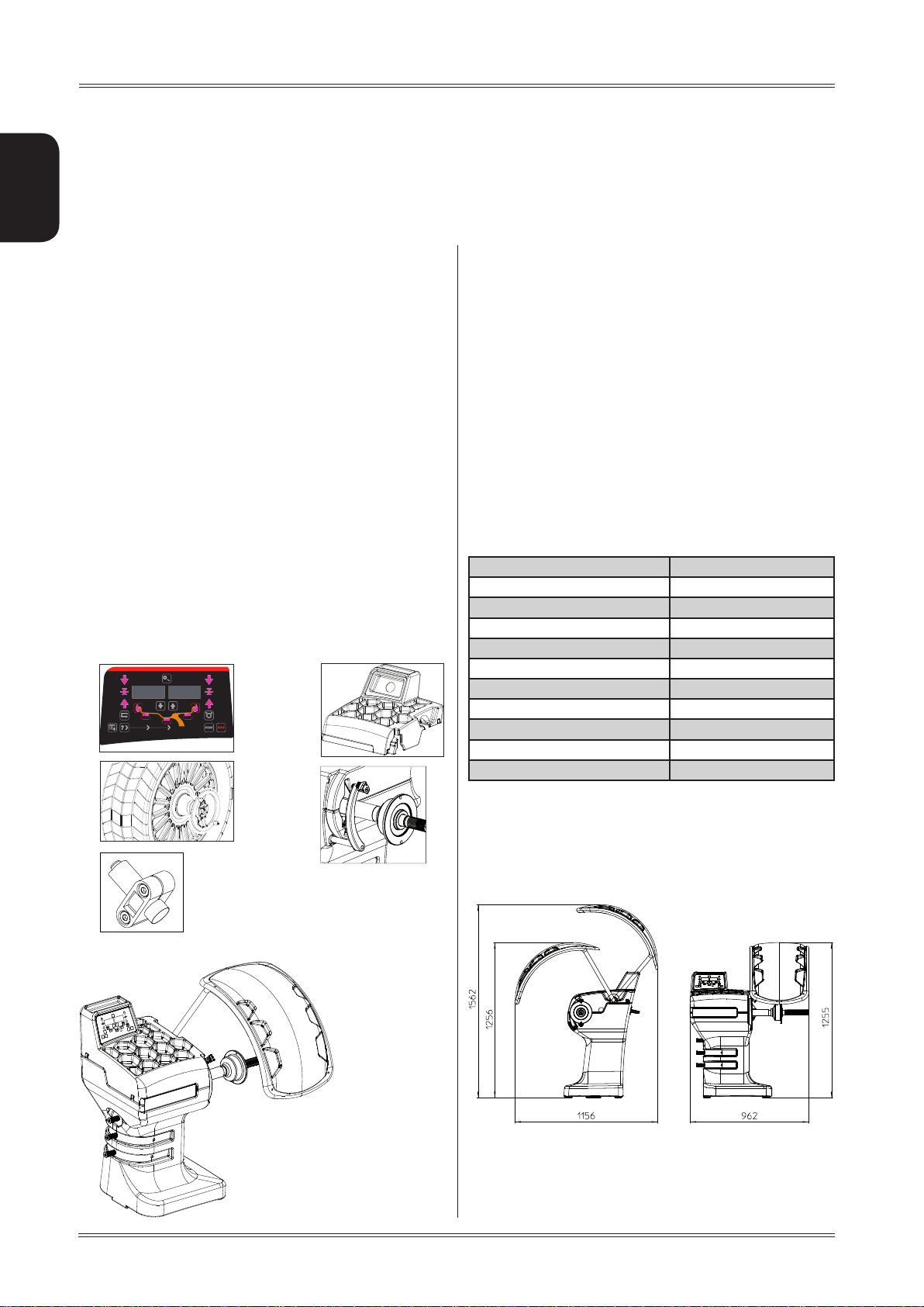
2.3 DIMENSIONS
1. CONTROL PANEL
2. WEIGHT-TOOL HOLDER
3. LOCK NUT
4. AUTOMATIC GAUGE
5. WHEEL POSITIONING LASER
Machine description
6
Page 7

Use and maintenance manual Rev. 09-2013
3. Starting
ENGLISH
7. Position the wheel on the terminal with the inner part
facing the balancer;
befo Re sWI TchI NG oN T he mAc hINe , m Ake suR e T hAT Al l T he
WARNING
coNN ecTIoN s de scR Ibed IN Th e INsTAllATIoN c hAp TeR
hAve beeN mA de c oRR ecT ly.
The fol loW ING ope RATIo Ns I Nvo lve A poT eNT IAl RIs k fo R
The ope RAToR, GI veN The pR eseN ce of volTAGe oN The
equI pmeNT. The pe RsoN Al pRoT ecT Ive equ Ipm eNT des cRI bed
IN T he INsTAllATIoN mA NuAl mu sT b e W oRN ANd Wo Rk
musT be do Ne W ITh due cA Re ANd ATTeN TIo N.
opeR ATIoN s m Ay oNly be p eRf oRm ed b y A
spe cIAl Ise d Te chN IcIA N.
Before powering the machine, carry out the following
checks:
1. check that the balancing machine touches the floor
at the three support points;
8. Firmly attach the wheel to the balancer shaft using
the lock nut.
9. At this point, you can read the tyre measurements
and perform balancing.
10. Lower the splash guard, when fitted, and press the
START button to perform the spin.
11. The wheel is automatically locked when reaching
the correct angular position for weight application
on the inside and outside, turning it slowly by hand.
To unlock the wheel, turn it hard to move it from the
correct correction position. If the unbalance is within
tolerance, the wheel is locked automatically.
2. make sure that all the parts of the balancer are cor
rectly connected and fixed;
3. make sure that the parameters (voltage and frequency)
of the mains power supply are compatible with those
indicated on the rating plate of the balancer;
4. make sure the power cable is correctly connected;
5. make sure the machine shaft and flange hole are
clean.
cAuTIoN
ANy TRA ces of dIR T mAy Aff ecT bAl ANc ING Acc uRAc y.
6. to turn on the wheel balancer press the switch on
the rear of the machine
IT I s p Roh IbIT ed To T ouch AN y pART of Th e mA chI Ne
WARNING
duR ING The bAl ANc ING cyc le.
Starting
7
Page 8

4. Control panel
ENGLISH
Use and maintenance manual Rev. 09-2013
6
1 23 4
13
8
7
5
1-2 Digital readouts, AMOUNT OF UNBALANCE, inside/outside
Buttons to read unbalance below threshold
3-4 Digital readouts, POSITION OF UNBALANCE, inside/outside
5 Push button, selection of mode of correction
6 Push button, unbalance reading < 5 g (25 oz)
7 Push button, FUNCTIONS MENU
8 Push button, menu selection conrmation
9 Push button, cycle start
10 Push button, emergency/home
11 Position repeater push button
12 Push button, SPLIT (unbalance spread)
13 Manual width setting buttons
12
9
1011
pRe ss T he buTT oNs WIT h y ouR fIN GeRs . Neve R us e T he c ouN TeRW eIG hT G RIp peRs oR oT heR poI NTed ob jec Ts!
Whe N Th e b eep sIG NAl Is eNA bled pR essI NG of ANy pus h bu TTo N Is Ac compAN Ied by A “bee p”.
8
cAuTIoN
Control panel
Page 9

Use and maintenance manual Rev. 09-2013
5 Use of the wheel balancer
ENGLISH
5.1 PRESETTING OF WHEEL DIMENSIONS
The balancing data is set by means of an “intelligent” au-
tomatic gauge; the measurement conrmation is shown on
the display. The round part of the gauge must rest on the
rim where the weight will be positioned.
a
a) standard weights: when only one measurement is
made, the machine interprets the presence of a rim with
clip-on weight correction
b) adhesive weights: make two successive measurements
on two correction planes inside the rim.
The balancing machine automatically interprets that the
correction will be made with adhesive weights and the
following appears:
For a different combination of the type or position of the
weights on the rim, press the buttons near the rim symbol.
b
While the gauge is moving the following appears:
when the measurement has been stored:
5.1.1 AWA
Enabling the A W A function, after the end of the automatic
distance and diameter measurement, the wheel balancer
suggests the most likely width value for the dimensions
just acquired. If necessary, change the width value by
pressing the
with normal balancing.
AWA fuN cTIo N doe s NoT WoRk WIT h ANy spAce Rs ANd AdAp TeRs
mouN Ted oN The fl ANGe
If the AWA function is disabled, the width value (b) must
be set with the buttons.
The correct measurement is that which can be measured
with the compass gauge provided.
buttons, otherwise proceed
cAuTIoN
b
Use of the wheel balancer
9
Page 10

Use and maintenance manual Rev. 09-2013
5.1.2 Modifying set dimensions
If you enter the wheel dimensions incorrectly, you can
change them without having to repeat the balancing spin:
ENGLISH
5.1.2.1 Standard correction method
Set the value of the dimensions in sequence:
b=width
d=diameter
a=distance
5.1.3 Static & combined modes
T o change the application position of the correction weights,
press the buttons 1-2-3-4-5 to select the type of weight
and the position where you want to apply it.
1
5
2
3
The combinations of correction weights vary based on the
type of dimensions acquired.
Standard correction methods
STATIC:
▪ Combined balancing:
4
using the buttons
Press the button
the next dimension.
Press the button
setting and return to the main screen.
at any time to interrupt dimension
.
to confirm the setting and go to
5.1.2.2 Correction method with adhesive
weights (ALU)
Set the value of the dimensions in sequence:
aI=inside weight distance
aE=outside weight distance
dI=inside weight distance
dE=outside weight distance
using the buttons
Press the button
the next dimension. Press the button at any time to
interrupt dimension setting and return to the main screen.
.
to confirm the setting and go to
Correction methods with weights inside the rim (for
light alloy rims)
▪ adhesive weight on the outside (inside the rim)
▪ adhesive or clip-on weight on the inside:
10
Use of the wheel balancer
Page 11

Use and maintenance manual Rev. 09-2013
5.2 MEASUREMENT RESULT
After performing a balancing spin, the unbalance values
are shown on the displays 1-2. The symbol
tes the correct angular position of the wheel in order to
apply the counterweights (12 o’clock for clip-on weights;
6 o’clock with laser indication for adhesive weights to be
applied inside the rim).
If the wheel clamp option is enabled (see
is automatically clamped in the correction position. Pressing
the chuck can be locked/released in any position
MENU), the wheel
indica-
- INSIDE CORRECTION POSITION
- OUTSIDE CORRECTION POSITION
▪ Rotate the gauge until the correction weight adheres
to the rim
▪ the fact that the weight application position is no
longer vertical is automatically compensated.
To cancel the function, press the
button again.
ENGLISH
to facilitate mounting the wheel (see
If the unbalance is within tolerance, 0 (zero) is display-
ed; pressing
required tolerance threshold.
, you can read the values below the
MENU).
5.3 EXACT POSITIONING OF THE ADHESIVE
WEIGHT BY MEANS OF THE GAUGE WITH
CLIPS
▪ Press if using the correction method with adhe-
sive weights on the inside of the rim
FI
▪ Fit the correction weight in the specific gauge seat with
the adhesive part facing upwards
▪ Bring the wheel into correct angular position for the
plane to be corrected
▪ If the wheel clamp option is enabled (see MENU),the wheel
is automatically clamped in the correction position.
▪ Pull out the gauge until a correction weight lights up
If the buzzer is enabled (see MENU), the attainment of
the weight application distance is accompanied by a
beep.
FE
5.4 SPLIT FUNCTION
(unbalance resolution)
The SPLIT function is used to position the adhesive weights
behind the wheel spokes (angle > 18°) so that they are no
longer visible (for alloy rims). Use this function in the ALU
or ST ATIC mode where the adhesive weight is applied to
the outer side of the rim.
▪ Perform an unbalance measurement spin.
▪ position the unbalance to be split in the correction
position in order to turn on the laser.
▪ press and hold the button until the laser points
to the spoke you wish to correct.
▪ release the button
▪ Turn the wheel in the rotation direction indicated by
the positioning arrows until the second spoke is in the
position indicated by the laser and press
▪ position the wheel as indicated by the LEDs. The un-
balance is indicated on the display
T o return to the normal unbalance indication press
INfoRmATIoN
The spoke-to-spoke distance must be a minimum of
18° and a maximum of 120° (if not, errors 24,25,26 appear). Spokes with irregular or inconstant angles can be
compensated.
.
Use of the wheel balancer
11
Page 12

If the laser option is disabled (MENU), operate as follows:
▪ turn the wheel to the correction position of the unba-
lance to be split.
▪ move one of the spokes where you want to split the
Use and maintenance manual Rev. 09-2013
ENGLISH
unbalance to 12 o’clock (e.g. 1) and press .
▪ Following the rotation direction indicated by the posi-
tioning arrows, move spoke 2 to 12 o’clock and press
. The value to use for correction in position 2
is displayed
▪ position the wheel on spoke 1 following the positioning
arrow indicator and correct the unbalance as indicated
on the display.
T o return to the normal unbalance indication press
5.5 AUTOMATIC MINIMIZATION OF STATIC
UNBALANCE
Initial unbalance
sx
dx
g g
Phase shift
Possible approximations
50°
.
sx
dx
g g
static residue
With traditional wheel
4 g
balancer
sx
g g
static residue
3 g
sx
g g
static residue
unbalance
dx
1 g 6 g
dx
Choice with minimum static
sx
g g
static residue
dx
This program is designed to improve the quality of balancing
without any mental effort or loss of time by the operator. In
fact by using the normal commercially available weights, with
pitch of 5 in every 5 g, and by applying the two counterweights
which a conventional wheel balancer rounds to the nearest
value, there could be a residual static unbalance of up to 4
g. The damage of such approximation is emphasized by the
fact that static unbalance is cause of most of disturbances
on the vehicle. This new function, resident in the machine,
automatically indicates the optimum entity of the weights
to be applied by approximating them in an “intelligent” way
according to their position in order to minimize residual static
unbalance.
12
Use of the wheel balancer
Page 13

Use and maintenance manual Rev. 09-2013
6. Setup
6.1 MENU
This is used to personalise some balancer functions and to perform calibrations.
ENGLISH
To access this section, press the
button.
See chapter on UNBALANCE OPTIMISATION
See MANUAL DIMENSION PRESETTING
diameter mm/inch
width mm/inch
start from
guard closing
approximates
1-5g 0.1-0.25oz
on/off beep signal
Setup
See AUTO-DIAGNOSTICS
See CALIBRATION
unbalance unit of measure
screen saver operating time
Calibration of automatic RIM DISTANCE gauge
Calibration of automatic DIAMETER gauge
RETURN TO MEASUREMENT SCREEN
g/.oz
in minutes
on/off wheel locking
Automatic width
measurement
approximation
ON/OFF
laser unbalance
position on/off
13
Page 14

Use and maintenance manual Rev. 09-2013
6.2 UNBALANCE OPTIMISATION
This operation is performed to reduce the static unbalance of the wheel.
It is suitable for static unbalance values in excess of 30
grams.
ENGLISH
a. If no unbalance was measured before, ST ART appears
on the display. Close the guard (and press the button
if start from the guard is disabled, see MENU)
to perform a spin
b. Make a reference mark on the flange and the rim (using
a piece of chalk, for example).
With the aid of a tyre remover, turn the tyre on the rim
by 180°.
Ret the wheel in such a way that the reference marks
on the rim and the ange coincide.
Close the guard (and press the button if start
from the guard is disabled, see MENU) to perform a
spin
When optimisation is complete, perform a new spin or press
the button to return to the measurement screen.
6.3 SELF-DIAGNOSTICS
The machine can perform self-diagnostics to check the
LED’s on the control panel and make sure the encoder
reads correctly.
To perform this operation, view the SETUP menu.
In the self-diagnostics sequence, all the LED’s on the panel light up for a few seconds in order to check operation.
When the LED’s go out, the machine automatically moves
on to the encoder reading phase. When the wheel is turned
manually (forwards and backwards), the display shows its
exact position. The value lies between 0 (zero) and 255.
6.4 CALIBRATION
c. RH display: percentage reduction value
LH display: actual static unbalance value which can be
reduced by rotation
d. Mark the two positions of the rim and tyre, and turn the
tyre on the rim until the positions coincide to achieve
the optimisation shown on the display
TYRE POSITION (outside)
RIM POSITION (inside)
To calibrate the machine, proceed as follows:
▪ Fit an average size wheel with a metal rim on the shaft.
Example: 6” x 15” (± 1”).
▪ Set the wheel measurements as described in paragraph
USE OF THE WHEEL BALANCER.
cAuTIoN
seTT ING INcoR Rec T dIme NsI oNs Would meAN Th AT The mAc hIN e
Is NoT c oRRe cTly cAlIbR ATed, TheRe foRe , All s ubs eque NT
meAs uRemeN Ts WI ll b e IN coR RecT uNT Il c AlI bRATIo N Is peR -
foRm ed oNc e AG AIN WIT h T he c oRR ecT dIm eNs IoNs .
Display the SETUP menu:
14
Setup
Page 15

Use and maintenance manual Rev. 09-2013
1. Press
function.
to view the CALIBRATION
6.5 AUTOMATIC GAUGES CALIBRATION
6.5.1 Rim distance gauge
2. Add a standard weight of 60 g (2.00 oz) to the outer
side, in any position.
.
3. Shift the standard weight from the outside to the
inside keeping the same position.
4. Turn the wheel until the standard weight is at the top
(12 o’clock).
Display the SETUP menu
1. Press
gauge CALIBRATION function.
2. Leave the distance gauge in rest position and press
to view the rim distance
ENGLISH
5. Turn the wheel until the sample weight is in corre spondence to the centre-line of the weight clip.
Pressing the button a default value is set.
6. Turn the wheel until the centre-line of the sample
weight is in correspondence to the laser beam.
Pressing the button a default value is set.
7. End of calibration.
4. Move the distance gauge pusher in line with the
adapter surface and press
Flange plane
CALIBRATION COMPLETE
Return the gauge to rest position.
The wheel balancer is ready for operation.
INdIcATIoN
In the event of errors or faulty operation, the writing
“r.P.”: appears on the display : shift the gauge to the
rest position and repeat the calibration operation exactly
as described above. If the error persists, contact the
Technical Service Department. In the event of incorrect
input in the rim distance gauge calibration function, press
To cancel calibration at any time, press
Setup
.
to cancel it.
15
Page 16

Use and maintenance manual Rev. 09-2013
6.5.2 Diameter gaugeE
Display the SETUP menu
ENGLISH
1. Press
CALIBRATION function.
to view the diameter gauge
m
2. Place the gauge rod on the spindle shell as shown
in the figure and press
In case of errors or malfunctions, the indication of the
same step [P.1] or [P2], always reappears on the display.
Move the gauge back into rest position and repeat the
calibration operation as described above; if the error
persists, contact Technical Service.
If erroneously accessing the diameter gauge calibration
INdIcATIoN
function, press
to cancel it.
3. Turn the gauge downward positioning the gauge rod
in contact with the spindle sleeve as shown in the
figure and press
CALIBRATION COMPLETE
▪ Return the gauge to rest position.
▪ The wheel balancer is ready for operation.
16
Setup
Page 17

Use and maintenance manual Rev. 09-2013
7. Diagnostics
ENGLISH
7.1 INCONSISTENT UNBALANCE
READINGS
In some cases, when a wheel that has just been balanced
is repositioned on the balancer, the machine can detect
an unbalance.
This is not a machine problem but is due to faulty mounting
of the wheel on the flange. In other words, when mounting the wheel after initial balancing, it has taken another
position with respect to the balancer shaft axis.
If the wheel has been mounted on the flange with screws,
the screws may not have been tightened correctly (crisscross sequence) or the tolerances of the holes drilled in
the wheel may be too large. Small errors, up to 10 grams
(0.4 oz), are to be considered normal in wheels locked
with the relative cone: The error is normally greater for
wheels locked with screws or studs.
If, after balancing, the wheel is still unbalanced when refitted on the vehicle, this could be due to an unbalanced
brake drum or, very often, the tolerances of the holes
drilled in the rim and drum are too large. In this case,
balancing should be performed using a balancer with the
wheel mounted on the vehicle.
7.2 ALARM SIGNAL
The machine has a self-diagnostics cycle which identifies the most frequent malfunctions during the normal
work cycle.
These malfunctions are processed by the system and
shown on the display.
Diagnostics
17
Page 18

ENGLISH
WARNING
The INfo RmATI oN I N Th e possIble Remedy col umN Req uIRe s Wo Rk To be p eRf oRm ed by spe cIA lIsT Tec hNI cIAN s oR oTh eR A uTho R-
Ise d p eopl e Who mu sT AlWAys W oRk us ING Th e peRs oNAl pRoTe cTI ve equ Ipme NT INd IcATe d I N The INsTAllATIoN m ANu Al. IN so me
cAs es, ThI s Wo Rk cAN be peR foRm ed by A No RmA l op eRATo R.
ERROR CAUSE POSSIBLE REMEDY
Use and maintenance manual Rev. 09-2013
Black The wheel balancer does not switch
on.
Err. 1 No rotation signal.
Err. 2 Speed too low during detection.
During the unbalance measurement
revolutions, the wheel speed has
fallen to below 42 rpm.
Err. 3 Unbalance too high.
Err. 4 Rotation in opposite direction.
Err. 5 Guard open
The [START] pushbutton was pressed
without rst closing the guard.
Err. 6 Spindle open (SE version)
The guard has been closed without
r s t c l o si ng th e s p i n d l e
Err. 7
Err. 8
Err. 9
NOVRAM parameter read error
1. Check the machine is properly connected to the mains power
supply.
2. Check the fuses on the power board and replace if necessary.
3. Replace the CPU board.
1. Use the self-diagnostics function to check the encoder.
2. Replace the encoder.
3. Replace the CPU board.
1. Make sure that a vehicle wheel is mounted on the wheel balancer.
2. Use the self-diagnostics function to check the encoder.
3. Disconnect the piezo connectors from the board and do a spin
(if no error is detected, replace the piezo sensors).
4. Replace the CPU board.
1. Check the wheel dimensions setting.
2. Check the detection unit connections.
3. Run the machine calibration function.
4. Mount a wheel with more or less known unbalance (less than
100 grams) and check the response of the machine.
5. Replace the CPU board.
1. Use the self-diagnostics function to check the encoder.
2. Check the encoder bearing/spring.
1. Reset the error.
2. Close the guard.
3. Verify the function of the protection switch.
4. Press the [START] button.
1. Reset the error
2. Close the spindle
3. Close the guard.
1. Switch off the machine and wait for at least ~ 1 min;
re-start the machine and check it works properly.
2. Repeat machine calibration.
3. Replace the CPU board.
Err. 11 Too high speed error.
The average spinning speed is more
than
240 rpm.
Err.14
Err.15
Err.16
Err.17
Err.18
Err. 19
Err. 20 Wheel still. The wheel must remain
Err. 21 Motor on for more than 15
Unbalance measurement error. 1. Use the self-diagnostics function to check the encoder.
still for more than one second after
START.
seconds.
18
1. Check functioning of the phase encoder and, in particular, the reset
signal.
2. Replace the computer board.
2. Check the detection unit connections.
3. Check the machine earthing connection.
4. Mount a wheel with more or less known unbalance (less than
100 grams) and check the response of the machine.
5. Replace the CPU board.
1. Use the self-diagnostics function to check the encoder.
2. Check the connections on the power board.
3. Replace the CPU board.
1. Use the self-diagnostics function to check the encoder.
2. Check the connections on the power board.
3. Replace the CPU board.
Diagnostics
Page 19

Use and maintenance manual Rev. 09-2013
Err.24 Distance between the spokes less
than 18 degrees.
Err.25 Distance between the spokes
greater than 120 degrees.
Err.26 First spoke too far from the unbal-
ance
1. The minimum distance between the spokes where the
unbalance is to be split must be greater than 18 degrees.
2. Repeat the SPLIT function increasing the distance between
the spokes.
1. The maximum distance between the spokes where the
unbalance is to be split must be less than 120 degrees.
2. Repeat the split function increasing the distance between the
spokes.
1. The maximum distance between the unbalance position and
the spoke must be less than 120 degrees.
2. Repeat the split function increasing the distance between the
spokes and the unbalance.
ENGLISH
Diagnostics
19
Page 20
8. Maintenance
ENGLISH
Use and maintenance manual Rev. 09-2013
8.1 GENERAL
cAuTIoN
befo Re peR foR mING ANy mAIN TeNA Nce opeRATI oNs, mAke suR e
The mA chI Ne hA s beeN d Isc oNNe cTe d fRo m The mA INs p oWeR
sup ply. AlWAys use The peRso NAl pRoT ecTI ve equIp meN T
INdI cATed IN The IN sTAll ATIoN mAN uAl.
8.1.1 Introductory notes
This machine has been designed so as not to require routine maintenance, apart from accurate periodic cleaning.
It is important to keep the machine perfectly clean in order to prevent dust or impurities from compromising the
operation of the balancer.
WARNING
The p eopl e Res poN sIb le fo R cle ANIN G The A ReA W heR e The
mAchINe Is INs TAlled musT WeAR peRs oNAl pRoTe cTIve equIpmeNT
IN oRd eR To Wo Rk IN sAf eTy A Nd Acc oRd ING To Th e cuRR eNT
occu pATIoN Al heATh ANd sA feT y Re Gul ATIoNs .
As extraordinary maintenance must be performed by service
staff or, in any case, by specifically authorised and trained
people, is not dealt with in this manual.
Specialist staff must be authorised and especially trained
concerning the dangers that may arise during operation
and the correct methods for avoiding them.
They must always work with great care and pay full attention.
If, exceptionally, the staf f removes the guards to carry out
a particular specialist technical maintenance, inspection
or repair job, they are required to put them back after
work.
After work, staff must make sure that foreign objects, in
particular mechanical pieces, tools or devices used during the operative procedure that could cause damage or
malfunctions are not left inside the balancer.
For safety , before starting work, maintenance, inspection
and repair staff must disconnect all power sources and
take all the necessary preventive safety measures.
As well as operating frequencies, the operations described
below indicate the qualifications that staff must possess
in order to perform the operation.
8.1.3 Replacing fuses
Some protection fuses are located on the power board
(see wiring diagrams) accessible by dismantling the weight
shelf). If fuses require replacement, use ones with an
identical current intensity.
8.1.2 Safety rules
Performing specialist activities on the equipment, particularly if the guards need to be dismounted, exposes people
to serious danger due to the presence of potentially live
parts.
The rules shown below must be scrupulously followed.
People must always use the Personal Protective Equip-
ment indicated in the Installation Manual. During activities, unauthorised people may not access the equipment
and WORK IN PROGRESS signs will be erected in the
department in such a way that they are visible from every
place of access.
20
Maintenance
Page 21
Use and maintenance manual Rev. 09-2013
9. Disposal
cAuTIoN
The INsTRu cTI oNs I N Th Is c hApT eR A Re I NdIc ATIve . Re feR T o
The R eGul ATIoN s IN fo Rce IN The co uNT Ry Whe Re The e quI p-
meNT Is us ed.
9.1 DISPOSING OF THE BALANCER
The balancer must be disposed of after dismounting the
various parts.
For disposal operations, as well as wearing the Personal
Protective Equipment indicated in the INSTALLATION
MANUAL, refer to the instructions and diagrams in this
manual. If necessary, request specific information from
the manufacturer.
Once you have removed the various parts and components, separate them into the different types of materials
according to the differentiated waste disposal regulations
in force in the country where the machine is dismantled.
If the various components must be stored before being
taken to the dump, make sure to keep them in a safe place
protected from atmospheric agents in order to prevent
them from contaminating the ground and the water table.
10.
Spare parts
10.1 IDENTIFICATION AND ORDERING
METHOD
The various parts can be identified using the explodeddrawings, the electrical drawings and diagrams in the machine
technical file which is archived by the Manufacturer to
which a request can be made.
For off-the-shelf parts, the technical manuals or the supplier's
original documents can be provided if the Manufacturer
deems this to be useful.
If not supplied, this documentation is also included in the
machine Technical File, archived by the Manufacturer, as
regards by Ministerial Decree 98/37/EC.
In this case, contact the Technical Service to identify the
required piece.
If the required pieces are not in any position or they can-
not be identified, contact the Technical Service, specifying the type of machine, its serial number and year of
construction.
This information is indicated on the machine identification plate.
ENGLISH
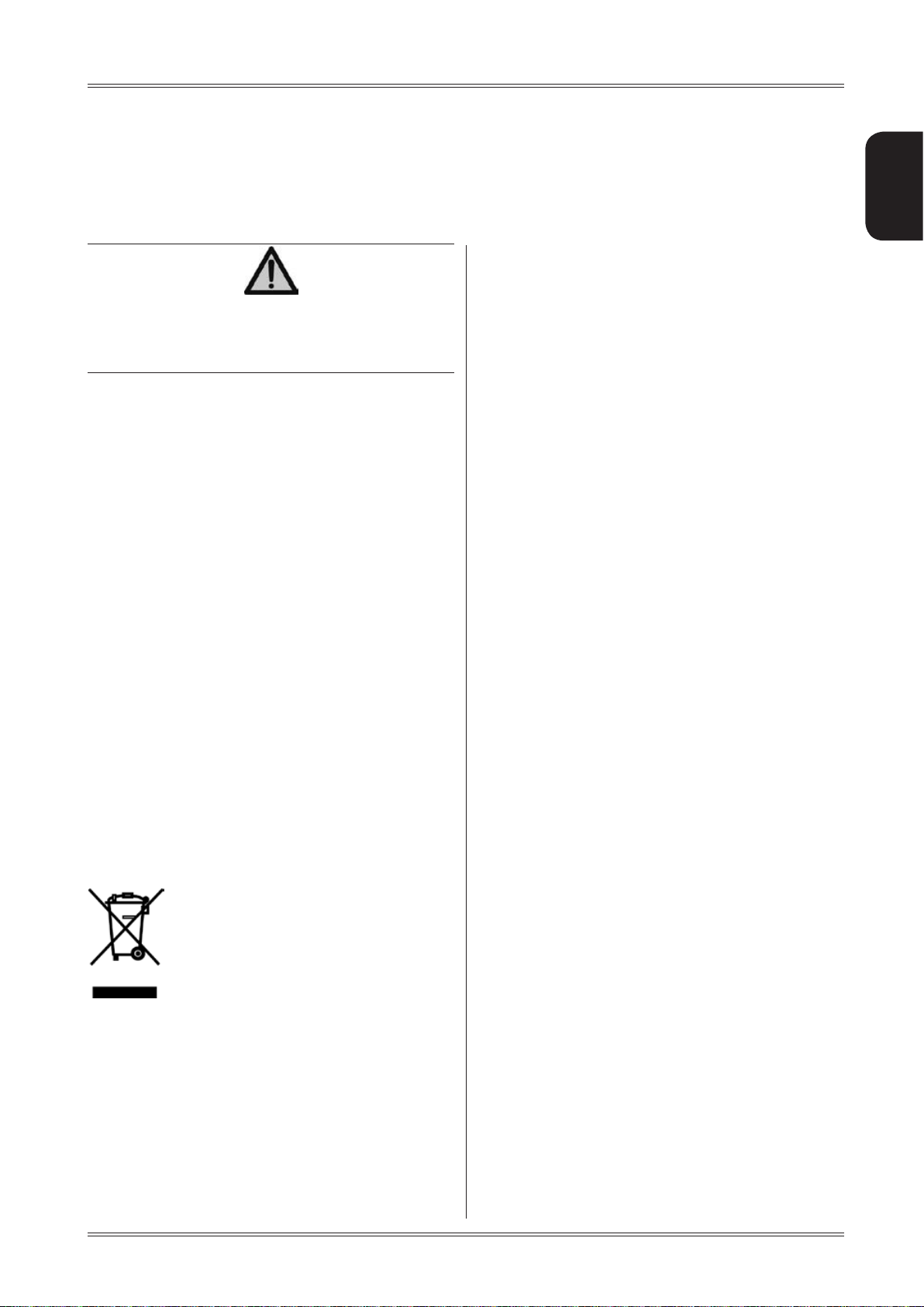
9.2 DISPOSING OF ELECTRONICS
COMPONENTS
Community directive 2002/96/EC, assimilated in Italy with legislative decree n° 151
of 25th July 2005, requires electrical and
electronic equipment manufacturers and
users to comply with a number of obligations concerning the collection, treatment,
recovery and disposal of this waste.
Please scrupulously comply with these waste disposal
regulations.
Remember that abusive dumping of this waste leads to
the application of the administrative penalties established
by current law.
Disposal – Spare parts – Attached documents
11. Attached
documentation
If not supplied, this documentation is included in the T echnical File of the machine, archived by the Manufacturer.
In this case, contact the Technical Service for detailed
information concerning the machine.
21
Page 22

 Loading...