

Page 1

ENGLISH
GB
Use and maintenance manual
General Index
1. FOREWORD 5
1.1 GENERAL 5
1.2 PURPOSE OF THE MANUAL 5
1.3 WHERE AND HOW TO KEEP THE MANUAL 5
1.4 MANUAL UPGRADES 6
1.5 COLLABORATION WITH USERS 6
1.6 MANUFACTURER 6
1.7 MANUFACTURER’S RESPONSIBILITY AND WARRANTY 6
1.7.1 Terms of warranty 6
1.8 TECHNICAL ASSISTANCE SERVICE 7
1.9 COPYRIGHT 7
2. INSTALLATION 8
3. MACHINE DESCRIPTION 12
3.1 MACHINE FUNCTION 12
3.2 TECHNICAL SPECIFICATIONS 13
3.3 DIMENSIONS AND WEIGHTS 13
3.4 WARNINGS 13
4. WHEEL LIFTING 16
5. WHEEL LOCKING 17
6. USE OF THE WHEEL BALANCING MACHINE 18
6.1 DIMENSION ACQUISITION 18
6.2 CORRECTION MODE SELECTION 19
I 0919 - 11/11 - Rev. B
Page 2

6.3 UNBALANCE UNIT OF MEASURE SELECTION 20
6.4 UNBALANCE MEASUREMENT (FIRST SET OF BUTTONS) 21
6.4.1 Lock/release wheel in correction position 22
6.5 UNBALANCE MEASUREMENT (SECOND SET OF BUTTONS) 23
6.6 THRESHOLD DISPLAY 24
6.7 UNBALANCE CORRECTION 25
6.7.1 Iron rims 25
6.7.2 Aluminium rims 26
6.7.3 Change weight application distance 27
6.8 UNBALANCE SPLIT 28
6.9 UNBALANCE OPTIMISATION 29
6.10 TYRE SET 30
6.10.1Tyresetvaluecerticate 32
6.10.2Tyresetcerticatecustomisation 32
6.11 WEIGHT STATISTICS 33
6.12 BALANCING CERTIFICATE PRINTOUT 35
6.12.1Balancingcerticatecustomisation 36
6.13 SCREENSAVER 40
6.14 WHEEL ANALYSIS 41
6.14.1 Runout 42
6.14.1.1 When and why TO USE MATCHING 42
6.14.1.2 Matching 43
6.14.1.2.1 When to perform matching 44
6.14.1.2.2 How to perform matching 45
6.14.1.3Peak/peakandrstharmonicgraphs 45
6.14.2 Tread 46
6.14.3 Taper 48
6.15 OUTSIDE RIM RUNOUT 49
7. WHEEL DISMOUNTING 51
8. SETUP 52
Page 3

8.1 MENU 52
8.2 GENERAL SETUP 53
8.2.
1 General setup 1/3 53
8.2.1.1 Screensaver customisation 55
8.2.2 General setup 2/3 56
8.2.3 General setup 3/3 57
8.3 RESERVED SETUP 58
8.3.1 LASER calibration 59
8.3.2 CC motor calibration 60
8.3.3 Spindle reset 61
8.3.4 Taper calibration 62
8.3.5 Correction weights 63
8.3.6 Wheel runout 64
8.3.7
Outside rim runout 65
8.3.8 Tread 66
8.3.9
Reserved for technical service
8.3.10 Saves the machine calibration 67
8.3.11 Loads the user manual 67
8.3.12 Firmware upgrade 68
8.3.13 Factory setting 69
8.4 MACHINE CALIBRATION 70
8.5 DIMENSIONS 71
8.6 SELF-DIAGNOSTICS 72
8.7 OSK 73
8.8 SOUNDS 74
8.9 INSTRUCTION MANUAL 74
9. Diagnostics 75
10. Maintenance 78
67
10.1 GENERAL 78
10.1.1 Introductory notes 78
10.1.2 Safety rules 78
10.1.3 Replacing fuses 78
Page 4

10.1.4 Periodic cleaning 78
11. Disposal 79
11.1 DISPOSING OF THE BALANCER 79
11.2 DISPOSING OF ELECTRONICS COMPONENTS 79
12. spare parts 79
12.1 IDENTIFICATION AND ORDERING METHOD 79
13. attacheD Documentation 79
Page 5

Use and Maintenance Manual Rev. 11-2011
1. Foreword
ENGLISH
1.2 PURPOSE OF THE MANUAL
This manual, and the installation manual, contains the
instructions required to use the machine safely and carry
out routine maintenance work.
Th I s m A N u A l Is A N I N T e G R A l p A R T o f T h e INsTAllATIoN
WARNING
m A N u A l W h I c h s h o u l d b e c o N s u l T e d c o N c e R N I N G s T A R T I N G
A N d u s I N G T h e m A c h I N e s A f e l y .
Re A d c A R e f u l l y b e f o R e c o N T I N u I N G .
1.1 GENERAL
The machine has been constructed in conformity with the
current EC Directives and the technical standards implementing the requirements, as stated in the declaration
of conformity issued by the manufacturer and attached
to the manual.
This publication, hereinafter simply referred to as ‘man-
ual’, contains all the information required to safely use
and service the machine referred to in the Declaration of
Conformity.
This appliance, hereinafter is generically referred to as
‘machine’.
The manual addresses operators instructed on the precautions to take in relation to the presence of electric current
and moving devices.
This publication is intended for all ‘users’ who as far as
within their competence need to and/or are obliged to
give instructions to others or operate on the machine
themselves.
These persons can be identified as follows:
- operators directly involved in transporting, storing,
installing, using and servicing the machine from when
it is put on the market until when it is scrapped;
- direct private users.
The original Italian text of this publication constitutes the
only reference to resolve any interpretation controversies
related to the translation into the European Community
languages.
This publication forms an integral part of the machine
and must therefore be kept for future reference until final
dismantling and scrapping of the machine.
Any calibrations, adjustments and extraordinary maintenance operations are not considered in this document as
they may only be performed by the service engineer who
must work on the machine according to the technical and
rated characteristics for which it was built.
Though it is fundamental to read this manual, it cannot
replace skilled technical staff who must be adequately
trained beforehand.
The foreseen use and configurations of the machine are
the only ones allowed by the manufacturer; do not attempt
to use the machine in a different way.
Any other use or configuration must be agreed in advance
with the manufacturer in writing and in this case an annex
will be attached to this manual.
For use, the user must also comply with the specific
workplace legislation in force in the country where the
machine is installed.
The manual also refers to laws, directives, etc., that the
user must know and consult in order to accomplish the
goals that the manual sets out to achieve.
1.3 WHERE AND HOW TO KEEP THE
MANUAL
This manual (and relative attachments) must be kept in
a safe and dry place and must always be available for
consultation.
Make a copy and keep it in the archive.
When exchanging information with the manufacturer or
the technical assistance staff authorised by the former,
quote the rating plate information and the serial number
of the machine.
This manual must be kept for the entire lifetime of the
machine, and if necessary (e.g.: damage making all or
some of it illegible, etc.) the user must request another
copy exclusively from the manufacturer, quoting the publication code indicated on the cover.
Introduction
5
Page 6

6
Use and Maintenance Manual Rev. 11-2011
ENGLISH
1.4 MANUAL UPGRADES
This manual is an integral part of the machine and reflects
the state of the art at the moment it was put on the market.
The publication complies with the directives in force on
that date; the manual cannot be considered inadequate
as a result of regulatory updates or modifications to the
machine.
Any manual upgrades that the manufacturer may see fit to
send to users will become an integral part of the manual
and must be kept together with it.
1.5 COLLABORATION WITH USERS
The manufacturer will be pleased to provide its customers with any further information they may require and will
consider proposals for improving this manual in order to
more fully satisfy the requirements it was written for.
In case of transfer of ownership of the machine,
which must always be accompanied by the use and
maintenance manual, the original user must inform
the manufacturer of the name and address of the
new user in order to allow it to send the new user
any communications and/or updates deemed to be
indispensable.
This publication is the property of the Manufacturer
and may not be fully or partly reproduced without prior
written agreement.
- never exceed the limits of use of the machine;
- always constantly and carefully clean and service the
machine;
- have the machine used by people of proven capacity
and attitude, adequately trained for the purpose.
The manufacturer declines all direct and indirect liability
caused by:
- use of the machine in a different way from that indicated
in this manual
- use of the machine by people who have not read and
fully understood the contents of this manual;
- use in breach of specific regulations in force in the
country of installation;
- modifications made to the machine, software and operating logic, unless authorised by the manufacturer
in writing;
- unauthorised repairs;
- exceptional events.
Transfer of the machine to a third party must also include
this manual; failure to include the manual automatically
invalidates all the rights of the purchaser, including the
terms of warranty, where applicable.
If the machine is transferred to a third party in a country with
a different language from the one written in this manual,
the original user shall provide a faithful translation of this
manual in the language of country in which the machine
will operate.
1.7.1 Terms of warranty
1.6 MANUFACTURER
The machine identification data is indicated on the plate
mounted on the machine.
The plate below is shown for the sake of example.
1.7 MANUFACTURER’S RESPONSIBILITY
AND WARRANTY
In order to make use of the manufacturer’s warranty, the
user must scrupulously observe the precautions contained
in the manual, in particular he must:
The Manufacturer guarantees the machines it manufacturers against all manufacturing or assembly faults for 12
(twelve) months from the date of collection or delivery.
The Manufacturer undertakes to replace or repair any part
which it deems to be faulty free of charge at its factory,
carriage paid.
If a Manufacturer’s repairman (or a person authorised by
the same) is required to work at the user’s facilities, the
relative travel expenses and board and lodging shall be
charged to the user.
The free supply of parts under warranty is always subject
to the faulty part being inspected by the manufacturer (or
a person authorised by the same).
The warranty is not extended following repairs or other
work done to the machine.
The warranty does not cover damage to the machine
deriving from:
- transport;
- neglect;
- improper use and/or use not in compliance with the
Introduction
Page 7

7
Use and Maintenance Manual Rev. 11-2011
ENGLISH
instructions in the operating manual
- incorrect electrical connections.
The warranty is invalidated in case of:
- repairs made by people who were not authorised by
the manufacturer;
- modifications that were not authorised by the manufacturer;
- use of parts and/or equipment that were not supplied
or approved by the manufacturer;
- removal or alteration of the machine identification
plate.
1.8 TECHNICAL ASSISTANCE SERVICE
For any technical service operation, contact the manufacturer
directly or an authorised dealer always quoting the model,
the version and the serial number of the machine.
1.9 COPYRIGHT
The information contained in this manual may not be
disclosed to third parties. Partial or total duplication, unless authorised by the Manufacturer in writing, through
photocopying, duplication or other systems, including
electronic acquisition, is breach of copyright and can lead
to prosecution.
Introduction
Page 8

8
Use and Maintenance Manual Rev. 11-2011
ENGLISH
2. Installation
Unpack the machine and place the front guard on the 1.
ground with the spindle locking/release pedal, the Zero
Weight lift and the side guard (1).
1
Do not install the machine in an area directly exposed 3.
to sunlight or where there are reflections from the floor.
The machine might malfunction if there is excess light
(3).
3
Avoid positioning objects made of a particularly reflecting 4.
material in the areas indicated in gray, as they might
interfere with laser reading (4).
4
Absolutely do not force the side column when unloading 2.
the machine from the pallet and be careful with the
electrical wiring (2).
2
Installation
Page 9

9
Use and Maintenance Manual Rev. 11-2011
ENGLISH
Hold up the lift using a wooden board (5)5.
5
Screw in the elbow union and fit all the wiring and 6.
pneumatic connectors inside the lift (6)
6
8
Connect the lift pedal cable with a male/female Faston 9.
(9)
9
7
Connect the footboard micro limit switch cable with a 10.
male/female Faston (10)
Connect the 8 Ø tube (7)7.
10
Connect the 140 Ø tube (8)8.
Installation
Page 10

10
Use and Maintenance Manual Rev. 11-2011
ENGLISH
11
12
Connect the pneumatic locking pedal microswitch cable 11.
with a male/female Faston (11)
8
Position and fasten the front footboard (12)12.
Position the lift with the footboard in line with the 14.
spindle (14)
14
Position the side guard and fasten it (13)13.
13
Installation
Page 11

11
25Nm
Use and Maintenance Manual Rev. 11-2011
ENGLISH
Drill the holes in the floor using a drill with an 8Ø bit and fit the expandable bolts provided as indicated in the 15.
drawing and tighten them to a torque of 25 Nm. As indicated in the box, in the last phase, fasten the mounting
brackets on the side of the column and tighten to a torque of 25Nm (15) .
15
Check that the mains input voltage and frequency 16.
parameters are compatible with the data shown on
the wheel balancing machine plate (±10%) (16).
16
Check proper pneumatic connection; the machine and 17.
the lift require at least 8 kg/cm² (~ 0.8 MPa; ~8 BAR;
~115 PSI) (17).
17
17
Turn on the machine and carry out 18.
operations:
▪ LASER CALIBRATION
▪ TAPER CALIBRATION
▪ MACHINE CALIBRATION
the following
Installation
Page 12

Use and Maintenance Manual Rev. 11-2011
3. Machine description
ENGLISH
3.1 MACHINE FUNCTION
It is a wheel balancing machine for cars, light commercial vehicles and 4-WDs .The wheels must weigh less than 75
kg. It can be operated in a temperature range of 0° to + 45° C.
It can operate only on a flat and non-resilient surface.
Do not mount any wheels other than motorcycle, car or truck wheels on the wheel balancing machine.
Thanks to the new and exclusive VDD (Virtual Direct Drive) system, reliable unbalance measurements can be made in
a short time, almost half the cycle time of other wheel balancing machines in this range.
TFT TOUCH SCREEN
WEIGHT TRAY
LASER POSITIONING
RIM INTERIOR LED LIGHT
PNEUMATIC LOCKING PEDAL
ZERO WEIGHT PEDAL
GUARD
CONE HOLDER
EXTERNAL SCANNING LASER
PNEUMATIC SPINDLE
INTERNAL SCANNING LASER
ZERO WEIGHT CARRIAGE LEVER
ZERO WEIGHT
The main features include:
Automatic dimension measurement ▪
Inside and outside rim eccentricity measurement ▪
Automatic minimisation of static unbalance ▪
Selection of optimal wheel mounting ▪
Customisable certificate printout ▪
Machine setting menu ▪
Unbalance optimisation ▪
Static program, ▪ ALUS; SPLIT; BPC; indication of exact position of the correction weights; self-diagnostics; self-
calibration
Statistics ▪ of weights used
12
Machine description
Page 13

Ø250mm
Zona d’azione laser scansione
Use and Maintenance Manual Rev. 11-2011
3.2 TECHNICAL SPECIFICATIONS
The following data refers to the wheel balancing machine
in its standard configuration.
Single phase power supply 115 /230 V 50/60 Hz
Protection class IP 54
Maximum power absorbed 0,15 kW
Balancing speed 100 min
Cycle time per wheel
Measurement uncertainty 0.5 g.
Average noise < 70 dB(A)
Rim width setting range 1.5”-20” or 40 - 510 mm
Settable diameter 10” ÷ 30” or 265 ÷ 765 mm
Min/max. compressed air pressure 8 ÷ 10 Kg/cm2
Machine weight 220 kg.
-1
4.7 seconds (5 3/4"x14") 15 Kg
~ 0.8 ÷ 1 Mpa;
~ 8 to 10 BAR;
~ 115 to 145 PSI.
3.3 DIMENSIONS
The function buttons are selected by pressing on the
TOUCH SCREEN.
cAuTIoN:
pR e s s T h e b u T T o N s oNly W I T h y o u R f I N G e R s .
Ne v e R u s e T h e c o u N T e R W e I G h T G R I p p e R s o R o T h e R p o I N T e d
o b j e c T s !
ENGLISH
3.4 WARNINGS
Machine description
Ke e p T h e A R e A I N d I c A T e d IN T h e f I G u R e f R e e o f T o o l s ,
cAuTIoN:
A d A p T e R s , e T c .
Scanning laser range
of action
13
Page 14

SE2-MOUNTING
A
C
B
D
E
G
F
SE2 MOUNTING
Page 15

360°
Cone
Quando possibile, centrare le ruote con cono dall'interno (vedi disegno).
Evitare di usare il manicotto RL con cerchi di ferro.
Whenever possible, centre the wheels with the cone from the inside (see the drawing
).
Avoid using the RL sleeve with metal rims.
Lorsque c’est possible, centrer les roues avec le cône de l’intérieur (voir dessin).
Eviter d’utiliser le manchon RL avec les jantes en fer.
Wenn möglich, die Räder mit Konus von Innen heraus zentrieren (siehe Zeichnung).
Bei Eisenfelgen die Verwendung der Muffe RL vermeiden.
Siempre que sea posible, centrar las ruedas con cono desde dentro (véase dibujo).
Evitar usar el manguito RL con llantas de hierro.
Quando possível, centre as rodas com cone pelo lado de dentro (ver
� gura).
Evite utilizar a luva RL com jantes de ferro.
SE2-DISMOUNTING
A
B
C
D
E
IT
GB
FR
DE
ES
PT
SE2 DISMOUNTING
Page 16

16
Use and Maintenance Manual Rev. 11-2011
ENGLISH
4. Wheel lifting
Zero Weight carriage lever
Pneumatic locking pedal Zero Weight pedal
Position the wheel on the carriage resting it against the ZERO WEIGHT carriage lever. Check that the pneumatic ▪
spindle is enabled for mounting (open); if not, push the pneumatic locking pedal.
Push the Zero Weight pedal. ▪
Ne v e R p u s h T h e Ze R o We I G h T p e d A l If T h e R e I s A N y o N e s T A N d I N G I N T h e R A N G e o f A c T I o N o f T h e l I f T .
be f o R e p u s h I N G T h e p e d A l T o l I f T A W h e e l , A l W A y s c h e c K T h A T T h e s p I N d l e I s o p e N
(I f N o T , T h e l I f T m I G h T N o T A s c e N d o R A s c e N d I N c o R R e c T l y ).
As soon as the wheel lifts off the ground, it is ready for mounting on the wheel balancing machine at zero weight.
cAuTIoN:
cAuTIoN:
Position the central hole of the wheel at the height of the spindle and slide the wheel onto the spindle with the aid ▪
of the Zero Weight carriage lever.
Wheel lifting
Page 17

17
Use and Maintenance Manual Rev. 11-2011
ENGLISH
5. Wheel locking
To lock/release the wheel on the pneumatic spindle, push the pneumatic locking pedal.
If T h e l I f T I s u p A N d T h e p N e u m A T I c l o c K I N G p e d A l I s p u s h e d T o l o c K T h e W h e e l o N T h e s p I N d l e ,
l I f T d e s c e N T W I l l A u T o m A T I c A l l y b e e N A b l e d .
Wheel locking
Page 18

18
Use and Maintenance Manual Rev. 11-2011
ENGLISH
6. Use of the wheel balancing machine
6.1 DIMENSION ACQUISITION
Acquires the wheel dimensions
Enables/disables taper and tread
measurement
Return to main screen
Outside rim eccentricity measurement
(use with the rim only)
NEW WHEEL
Press the button to acquire the dimensions.
Close the guard to perform the balancing spin.
ATTeNZIoNe
be f o R e p R e s s I N G T h e b u T T o N , p o s I T I o N T h e W h e e l IN s u c h A W A y T h A T A N y W e I G h T s A l R e A d y o N T h e R I m d o N o T f A l l W IT hI N
T h e R e A d I N G A R e A o f T h e I N T e R N A l l A s e R , T h A T W A y e x c l u d I N G A N y d I m e N s I o N m e A s u R I N G I N A c c u R A c I e s .
WHEEL THE SAME AS PREVIOUS
Close the guard to perform the balancing spin.
The machine in any case checks the wheel dimensions and if they are different from the previous wheel, automatically
measures them again. With this innovative system you can balance a set of 4-5 wheels measuring the dimensions
only once, thus saving a lot of time.
TAPER AND TREAD MEASUREMENT AT THREE POINTS
Press the button to enable/disable complete taper and tread measurement.
This function uses a special measuring cycle that extends the cycle time by a few seconds.
The setting remains stored even when the wheel balancing machine is turned off.
OUTSIDE RIM ECCENTRICITY MEASUREMENT WITHOUT TYRE
Press the button ( OUTSIDE RIM RUNOUT )
CANCEL DIMENSION SETTING
Press the button .
Use of the wheel balancing machine
Page 19

19
Use and Maintenance Manual Rev. 11-2011
ENGLISH
for
6.2 CORRECTION MODE SELECTION
Press from the unbalance measurement screen.
Goes back to the unbalance measurement
screen, automatically recalculating the
unbalance values.
Press the weight symbol in the desired correction position.
If doing the unbalance correction in static mode only, press the outside adhesive weight symbol
once or twice (depending on the current correction mode).
Use of the wheel balancing machine
Page 20

20
Use and Maintenance Manual Rev. 11-2011
ENGLISH
6.3 UNBALANCE UNIT OF MEASURE selection
Press the button / from the unbalance measurement screen
Selects grams
Selects ounces
Allows selecting whether to view the unbalance values expressed in grams or ounces.
Use of the wheel balancing machine
Page 21

21
Use and Maintenance Manual Rev. 11-2011
ENGLISH
6.4 UNBALANCE MEASUREMENT (first set of buttons)
Displays the information screen
Selects unbalance display in g/oz
Displays the threshold
Enables/disables wheel in correction position
Splits the unbalance
Displays the second set of buttons
Lift reset with wheel stopped / STOP during spin
To perform an unbalance measurement spin, close the guard.
After performing a balancing spin, the following are displayed:
The unbalance values.1.
White: wheel locked in correction position / Internal scanning laser positioned on the side. ▪
Light blue: position not reached / Internal scanning laser not positioned. ▪
The red weights that indicate the unbalance position.2.
The weight shadows that indicate where the correction weight should be applied: at the top at 12 o’clock or at the 3.
point indicated by the internal laser.
If T h e “W h e e l I N p o s I T I o N ” s o u N d I s e N A b l e d , A s o u N d W I l l b e e m I T T e d W h e N T h e c o R R e c T I o N p o s I T I o N h A s b e e N R e A c h e d .
If T h e u N b A l A N c e I s l e s s T h A N T h e T h R e s h o l d v A l u e s e T , oK I s d I s p l A y e d I N s T e A d o f T h e u N b A l A N c e v A l u e T o I N d I c A T e T h A T T h e
pR e s s I N G T h e b u T T o N y o u c A N IN A N y c A s e v I e W T h e R e s I d u A l u N b A l A N c e .
W h e e l I s WI T hI N T o l e R A N c e o N T h A T s I d e .
To R e s u m e W I T h T h e d I m e N s I o N s o f T h e W h e e l m o u N T e d , o p e N A N d c l o s e T h e s p I N d l e .
when on, it indicates that the lasers are moving
when on, it indicates that the lift pedal is pressed
Use of the wheel balancing machine
Page 22

22
Use and Maintenance Manual Rev. 11-2011
ENGLISH
when on, it indicates that the wheel locking pedal is pressed
when on, it indicates that the spindle is closed
when on, it indicates that wheel positioning is enabled.
6.4.1 Lock/release wheel in correction position
The wheel balancer automatically keeps the wheel in the correction position on one of the sides. To release it press
.
If the wheel has been released and you need to move it into the correction position again, press .
Use of the wheel balancing machine
Page 23

23
Use and Maintenance Manual Rev. 11-2011
ENGLISH
6.5 UNBALANCE MEASUREMENT (second set of buttons)
Prints the unbalance values
Displays the weight statistics
Menu
Unbalance optimisation
Goes back to the first set of buttons
Lift reset with wheel stopped / STOP during spin
Use of the wheel balancing machine
Page 24

24
Use and Maintenance Manual Rev. 11-2011
ENGLISH
6.6 THRESHOLD DISPLAY
Displays the information screen
Selects unbalance display in g/oz
Displays the approximate values
Enables/disables wheel in correction position
Splits the unbalance
Displays the second set of buttons
Lift reset with wheel stopped / STOP during spin
Press to view the residual unbalance values with an accuracy of 0.5 g. (0.1oz).
Press to go back to display of the approximate values.
Use of the wheel balancing machine
Page 25

25
Use and Maintenance Manual Rev. 11-2011
ENGLISH
6.7 UNBALANCE CORRECTION
After an unbalance measurement spin, the weight shadow indicates the correct application point.
6.7.1 Iron rims
Displays the information screen
Selects unbalance display in g/oz
Displays the approximate values
Enables/disables wheel in correction position
Unbalance split (not selectable for correction with
clip-on weights)
Displays the second set of buttons
Lift reset with wheel stopped / STOP during spin
WEIGHT APPLICATION POSITION
Correction type Inside Outside
Clip-on weight at 12 o’clock Clip-on weight at 12 o’clock
Clip-on weight at 12 o’clock Adhesive weight at 12 o’clock
Adhesive weight at the point indicated
by the internal laser
Clip-on weight at 12 o’clock
Adhesive weight at the point indicated
Use of the wheel balancing machine
by the internal laser
Adhesive weight at the point indicated by the internal laser
Adhesive weight at 12 o’clock
Page 26

26
Use and Maintenance Manual Rev. 11-2011
ENGLISH
6.7.2 Aluminium rims
Displays the information screen
Selects unbalance display in g/oz
Displays the approximate values
Enables/disables wheel in correction position
Splits the unbalance
Displays the second set of buttons
Lift reset with wheel stopped / STOP during spin
After the spin, the laser indicates the outside correction point; once you have applied the weight, press the “laser
positioning” button ( MACHINE DESCRIPTION) positioned on the weight tray of the wheel balancing machine to
move the laser so that it indicates the inside correction position.
The inside unbalance values indicated by the laser are graphically displayed in white.
WEIGHT APPLICATION POSITION
Correction type Inside Outside
Adhesive weight at the point indicated
by the internal laser
Clip-on weight at 12 o’clock
Adhesive weight at the point indicated by the
internal laser
Adhesive weight at the point indicated by the
internal laser
Use of the wheel balancing machine
Page 27

27
Use and Maintenance Manual Rev. 11-2011
ENGLISH
6.7.3 Change weight application distance
To change the correction positions indicated by the laser and automatically calculated by the machine, operate as
follows:
Position on the side to be changed by pressing the laser positioning button.1.
Press 2.
Move the wheel by hand to move the laser. 3.
When you have reached the desired position, press the button 4.
To cancel this operation, press the button : The laser automatically goes back to indicating the correction
position previously saved.
Use of the wheel balancing machine
Page 28

28
Use and Maintenance Manual Rev. 11-2011
ENGLISH
6.8 UNBALANCE SPLIT
The split function is enabled for the outside of aluminium rims ( ALUMINIUM RIMS) and is used to hide any adhesive
unbalance correction weights behind the rim spokes.
To split the unbalance measured in two different positions, proceed as follows:
With the wheel in the outside correction position, 1.
press the button to release it.
Sele2. ct a spoke close to the position indicated by the
laser and press the button
Th e W h I T e l I N e o N T h e R I m I N d I c A T e s T h e u N b A l A N c e
If T h e s y m b o l A p p e A R s , I T m e A N s T h A T y o u c A N N o T
c o R R e c T I o N p o s I T I o N N o T s p l I T .
s e l e c T T h e f I R s T s p o K e A T T h A T p o I N T
(m A x I m u m d I s T A N c e 150°).
Turn the wheel in the direction indicated on the screen 3.
and select the second spoke by pressing the button
If T h e s y m b o l A p p e A R s , I T m e A N s T h A T y o u c A N N o T
s e l e c T T h e s e c o N d s p o K e A T T h A T p o I N T
(m I N I m u m d I s T A N c e 18°, m A x I m u m d I s T A N c e 120°).
At this stage, two indications appear on the screen for 4.
positioning of the unbalance correction weights.
To cancel the split, press the button :
Any error in this procedure is clearly shown on screen.
Use of the wheel balancing machine
Page 29

29
Use and Maintenance Manual Rev. 11-2011
ENGLISH
6.9 UNBALANCE OPTIMISATION
Confirm
Return to main screen
Press the button from the second set of buttons on the unbalance measurement screen after performing a
balancing spin.
Th I s f u N c T I o N c A N N o T b e A c c e s s e d If y o u h A v e N o T f I R s T p e R f o R m e d A b A l A N c I N G s p I N .
The program allows total wheel unbalance to be reduced by compensating, when possible, tyre and rim unbalance
values. It requires two spins, rotating the tyre on the rim on the second spin.
At the end of the procedure, mark the rim and tyre positions indicated by the machine with a piece of chalk and remount both so that they coincide.
Use of the wheel balancing machine
Page 30

30
Use and Maintenance Manual Rev. 11-2011
ENGLISH
6.10 TYRE SET
Selects any one-way direction of the wheel
Prints the tyre set values
Return to main screen
This function allows balancing the four wheels of a vehicle, plus the spare wheel if necessary, and obtaining information
on how to mount them in order to reduce to a minimum the vibrations due to the residual eccentricity of each wheel.
The TYRE SET function can be enabled or disabled from the MENU; to best use this function, proceed as follows:
Prepare adhesive symbols to identify the wheels.1.
Mount the first wheel, measure the dimensions, balance it and identify it with the number 1.2.
Dismount the wheel and mount the next one, close the guard and balance the wheel without acquiring the 3.
dimensions again.
Repeat step 3 for the remaining 3 wheels, plus any spare wheel, each time identifying the wheel with a progressive 4.
number from 2 to 5.
Each time the spindle is opened, the wheel balancing machine indicates the best way to mount the wheels balanced 5.
up to that point. On the left-hand side of the screen, a stylized vehicle is displayed with the four tyres plus the
spare wheel; at each spin, the number of the wheel to be mounted in each position is indicated on each of them
(right/left front/rear axle).
The procedure can be reset by measuring the dimensions like for a new wheel. If the spindle is incorrectly opened, 6.
the balancing sequence is interrupted and consequently the end result will be incorrect.
To view a summary table with the wheel values, press the button 7. :
Static residual unbalance
Radial runout
Tread measured as one value
Tread measurement
Wheel taper
Use of the wheel balancing machine
Page 31

31
Use and Maintenance Manual Rev. 11-2011
ENGLISH
In the case of directional wheels, i.e. which can be mounted only on the right or only on the left, press the button
to set the direction:
Left ▪
Right ▪
Left/right ▪
The machine changes and immediately displays the new mounting order.
The wheel mounting order is established based on the residual radial eccentricity value of each wheel.
To manually set the order of the wheels press:
drag one wheel at a time to the desired position on the vehicle drawing and drop it when
+
AT e A c h u N b A l A N c e R e c A l c u l A T I o N , T h e T y R e s e T s e T T I N G G o e s b A c K T o b e I N G b A s e d o N T h e W h e e l R u N o u T .
the edges turn green
Resets the manual setting
Use of the wheel balancing machine
Page 32

32
Use and Maintenance Manual Rev. 11-2011
ENGLISH
6.10.1 Tyre set value certificate
Press the button from the tyre set value summary screen.
LOGO
Saves the certificate to USB key
Loads the certificate from USB key
Prints the unbalance values
Return to main screen
6.10.2 Tyre set certificate customisation
Follow the instructions for customising the balancing certificate ( BALANCING CERTIFICATE CUSTOMISATION).
The .htm file to be customised is TyreSet.htm.
Use of the wheel balancing machine
Page 33

33
Use and Maintenance Manual Rev. 11-2011
ENGLISH
6.11 WEIGHT STATISTICS
Clip-on weight graph
No. of daily spins:Indicates the number of spins performed by the machine per day
Total no. of spins: Indicates the number of spins performed by the machine starting from the reset date.
The two tables list all the weights (clip-on and adhesive) used starting from the reset date.
Adhesive weight graph
Resets the statistics
Displays the statistics of the weights used in grams
and ounces
Return to main screen
When the RESET STATISTICS button is pressed, a pop-up menu appears that allows selecting which parameters
to reset.
Selects the counter to reset
Deselects the counter to reset
Resets the counters selected
Goes back to the measurement screen
Appears if the relative counter is selected to be reset.
Use of the wheel balancing machine
Page 34

34
Use and Maintenance Manual Rev. 11-2011
ENGLISH
Pressing on the buttons in the table header, graphic
display of the statistics of the weights used is enabled, which allows more intuitively understanding
the most common types of weight adopted.
Use of the wheel balancing machine
Page 35

35
Use and Maintenance Manual Rev. 11-2011
ENGLISH
6.12 BALANCING CERTIFICATE PRINTOUT
Press the button from the second set of buttons on the unbalance measurement screen.
LOGO
Saves the certificate to USB key
Loads the certificate from USB key
Prints the unbalance values
Return to main screen
Use of the wheel balancing machine
Page 36

36
USB PORT
Use and Maintenance Manual Rev. 11-2011
ENGLISH
6.12.1 Balancing certificate customisation
Insert a USB key in the port at the rear of the machine.
Press to save the certificate management files to the USB key.
Afoldercalled“Certif”iscreatedonthekeycontainingallthelestobeeditedtocustomisethebalancing
certicate:
Use of the wheel balancing machine
Page 37

37
Use and Maintenance Manual Rev. 11-2011
ENGLISH
File to be customised using an HTML editor (FinalCertificate.htm):
LOGO
Balancing certificate logo: 1241 × 278 pixel. It can be replaced with a personalised logo.
LOGO
Use the following codes to insert the possible printable values in the balancing certificate.
Field
Generic
#1# Date
#2# Time
Actual unbalances values
#10# Internal unbalance valueP2
#11# External unbalance value
#12# Static unbalance value
Run-out
#20# Radial run-out value
#21# Rim run-out value
#22# Tyre run-out value
#23# Tyre tread depht.
#30# Unbalance unit measure (g/oz)
Use of the wheel balancing machine
Units
Page 38

38
Use and Maintenance Manual Rev. 11-2011
ENGLISH
#31# Run-out unit measure (mm/”)
Tire set
#40# Radial run-out value for wheel nr.1
#41# Tyre tread depht. for wheel nr.1
#42# Internal unbalance value for wheel nr.1
#43# External unbalance value for wheel nr.1
#44# Static unbalance value for wheel nr.1
#45# Radial run-out value for wheel nr.2
#46# Tyre tread depht. for wheel nr.2
#47# Internal unbalance value for wheel nr.2
#48# External unbalance value for wheel nr.2
#49# Static unbalance value for wheel nr.2
#50# Radial run-out value for wheel nr.3
#51# Tyre tread depht. for wheel nr.3
#52# Internal unbalance value for wheel nr.3
#53# External unbalance value for wheel nr.3
#54# Static unbalance value for wheel nr.3
#55# Radial run-out value for wheel nr.4
#56# Tyre tread depht. for wheel nr.4
#57# Internal unbalance value for wheel nr.4
#58# External unbalance value for wheel nr.4
#59# Static unbalance value for wheel nr.4
#60# Radial run-out value for wheel nr.5
#61# Tyre tread depht. for wheel nr.5
#62# Internal unbalance value for wheel nr.5
#63# External unbalance value for wheel nr.5
#64# Static unbalance value for wheel nr.5
#65# Right front tyre number
#66# Left front tyre number
#67# Right rear tyre number
#68# Left rear tyre number
#69# Spare tyre number
#70# Tyre tread depht. 3 zones for wheel nr.1
#71# Tyre tread depht. 3 zones for wheel nr.1
#72# Tyre tread depht. 3 zones for wheel nr.1
#73# Tyre tread depht. 3 zones for wheel nr.2
#74# Tyre tread depht. 3 zones for wheel nr.2
#75# Tyre tread depht. 3 zones for wheel nr.2
#76# Tyre tread depht. 3 zones for wheel nr.3
#77# Tyre tread depht. 3 zones for wheel nr.3
#78# Tyre tread depht. 3 zones for wheel nr.3
#79# Tyre tread depht. 3 zones for wheel nr.4
#80# Tyre tread depht. 3 zones for wheel nr.4
#81# Tyre tread depht. 3 zones for wheel nr.4
#82# Tyre tread depht. 3 zones for wheel nr.5
#83# Tyre tread depht. 3 zones for wheel nr.5
#84# Tyre tread depht. 3 zones for wheel nr.5
#85# Conicity value for wheel nr.1
#86# Conicity value for wheel nr.2
#87# Conicity value for wheel nr.3
Use of the wheel balancing machine
Page 39

39
Use and Maintenance Manual Rev. 11-2011
ENGLISH
Runout
#90# PP wheel runout
#91# I harmonic wheel runout
#92# II harmonic wheel runout
#93# III harmonic wheel runout
#94# IV harmonic wheel runout
#95# PP rim runout
#96# I harmonic rim runout
#97# II harmonic rim runout
#98# III harmonic rim runout
#99# IV harmonic rim runout
Rim Runout
#100# PP internal rim runout
#101# I harmonic internal rim runout
#102# II harmonic internal rim runout
#103# III harmonic internal rim runout
#104# IV harmonic internal rim runout
#105# PP external rim runout
#106# I harmonic external rim runout
#107# II harmonic external rim runout
#108# III harmonic external rim runout
#109# IV harmonic external rim runout
Edit the Finalcertificate.htm file based on your needs and save it to the USB key.
Insert the key in the machine and press
to reload the customised balancing certificate.
Use of the wheel balancing machine
Page 40

40
Use and Maintenance Manual Rev. 11-2011
ENGLISH
6.13 SCREENSAVER
CUSTOMISED SCREENSAVER
If the machine is not used and remains on the initial screen for longer than the time settable from the menu, the
screensaver is automatically activated. Pressing on the screen at any point or moving the wheel, the main screen will
automatically be activated. Automatic start-up operated by the protection system is not available from the screensaver for safety reasons.
Use of the wheel balancing machine
Page 41

41
Use and Maintenance Manual Rev. 11-2011
ENGLISH
6.14 WHEEL ANALYSIS
Press the button from the first set of buttons on the measurement screen.
Goes to the peak/peak and first harmonic graph screen
Goes to the tread analysis screen
Prints the information screen
Return to main screen
This screen shows all the data read in the various unbalance measurement and wheel analysis phases.
For more information, refer to the paragraphs 6.14.1 RUNOUT, 6.14.2 TREAD, 6.14.3 TAPER .
The button is displayed with a red I when:
The first harmonic of the wheel runout exceeds the limit set in the setup parameters. ▪
The tread value is less than the limit set in the setup parameters. ▪
The wheel taper value is considered critical (indicator on yellow level) or unacceptable (indicator on red level). ▪
Use of the wheel balancing machine
Page 42

42
Use and Maintenance Manual Rev. 11-2011
ENGLISH
wheel
wheel
wheel
6.14.1 Runout
6.14.1.1 When and why TO USE MATCHING
The software associated with the eccentricity measurement is a powerful tool to determine the need to perform
the relative rotation between the wheel and the rim in
order to reduce the eccentricity to within acceptable limits. The criterion used is based on the fact that a rim with
acceptable tolerance, mounted with acceptable tyre, can
statistically generate an unacceptable total eccentricity
that can be improved by matching.
ER 100 is capable of automatically measuring the eccentricity of both the tyre and the rim from the inside.
The latter measurement generally corresponds to the rim
eccentricity in the tyre fitting area.
virtual wheel
rim
tyre
rotation axis
Th e R I m c A N b e m e A s u R e d m o R e A c c u R A T e l y u s I N G T h e s p e c I f I c
p R o G R A m W I T h o u T T h e T y R e .
Example 1
virtual wheel
tyre
rotation axis
rim
Tyre - 0.6 mm
Wheel + 0,3 mm
The eccentricity of the single elements is compensated.
The wheel is acceptable.
Example 3
virtual wheel
rim
tyre
rotation axis
Rim + 0.8 mm
Tyre + 0.6 mm
Wheel + 1.3 mm
The wheel eccentricityis excessive because an acceptable
rim or tyre has randomly been positioned in an “unfor-
tunate” position”.
SOLUTION: turn the tyre on the rim by 180°
RESULT: wheel eccentricity 0.3 – 0.4 mm (in tolerance)
Rim + 0.8 mm
Rim - 0 mm
Tyre + 1,2 mm
Wheel + 1.2 mm
The wheel eccentricity cannot be compensated by the rota-
tion because the rim is perfect!
SOLUTION: turn the tyre on the rim by 180°
RESULT: No improvement.
Use of the wheel balancing machine
Page 43

43
Use and Maintenance Manual Rev. 11-2011
ENGLISH
6.14.1.2 Matching
Goes to the peak/peak and first harmonic graph
screen.
Goes to the tread analysis screen
Prints the information screen
Return to main screen
The rim and wheel runout measurements are automatically made during the unbalance measurement cycle and no
extra time is required.
The purpose of these measurements is to check whether it is possible to reduce the total wheel runout by turning
only the tyre on the rim.
The information shown on the screen is:
Grey rim: outer tyre surface
Yellow rim: rim surface
: Tyre runout position (moved by turning the wheel)
: Rim runout position (moved by turning the wheel)
When highlighted:
indicates that the tyre needs to be marked with a piece of chalk at the top at 12
o’clock.
When highlighted:
indicates that the rim needs to marked with a piece of chalk at the top at 12 o’clock.
Wheel runout (rim plus tyre):
GREEN background: value less than the first harmonic limit set in wheel runout set-
RED background: value out of tolerance because greater than the first harmonic
Tyre runout
Rim runout
Use of the wheel balancing machine
up.
limit set in wheel runout setup.
Page 44

44
Use and Maintenance Manual Rev. 11-2011
ENGLISH
Estimated residual wheel runout after matching:
GREEN background: after matching, the runout will be in tolerance (with respect to the
first harmonic correction limit value set in wheel runout setup).
RED background: after matching, the runout will be out of tolerance (with respect
to the first harmonic correction limit value set in wheel runout
setup), therefore, the eccentricity problem cannot be improved
with matching.
Estimated percentage gain relating to reduction of the first harmonic value obtained after
matching.
6.14.1.2.1 When to perform matching
It is advisable to perform matching if the wheel runout value is displayed on a red background and the residual wheel
runout value is displayed in the Match box on a green background.
6.14.1.2.2 How to perform matching
Turn the wheel and mark the tyre and the rim with a piece of chalk at the two points indicated in the graph. ▪
Turn the tyre on the rim until the two marks coincide. ▪
Use of the wheel balancing machine
Page 45
45
Use and Maintenance Manual Rev. 11-2011
ENGLISH
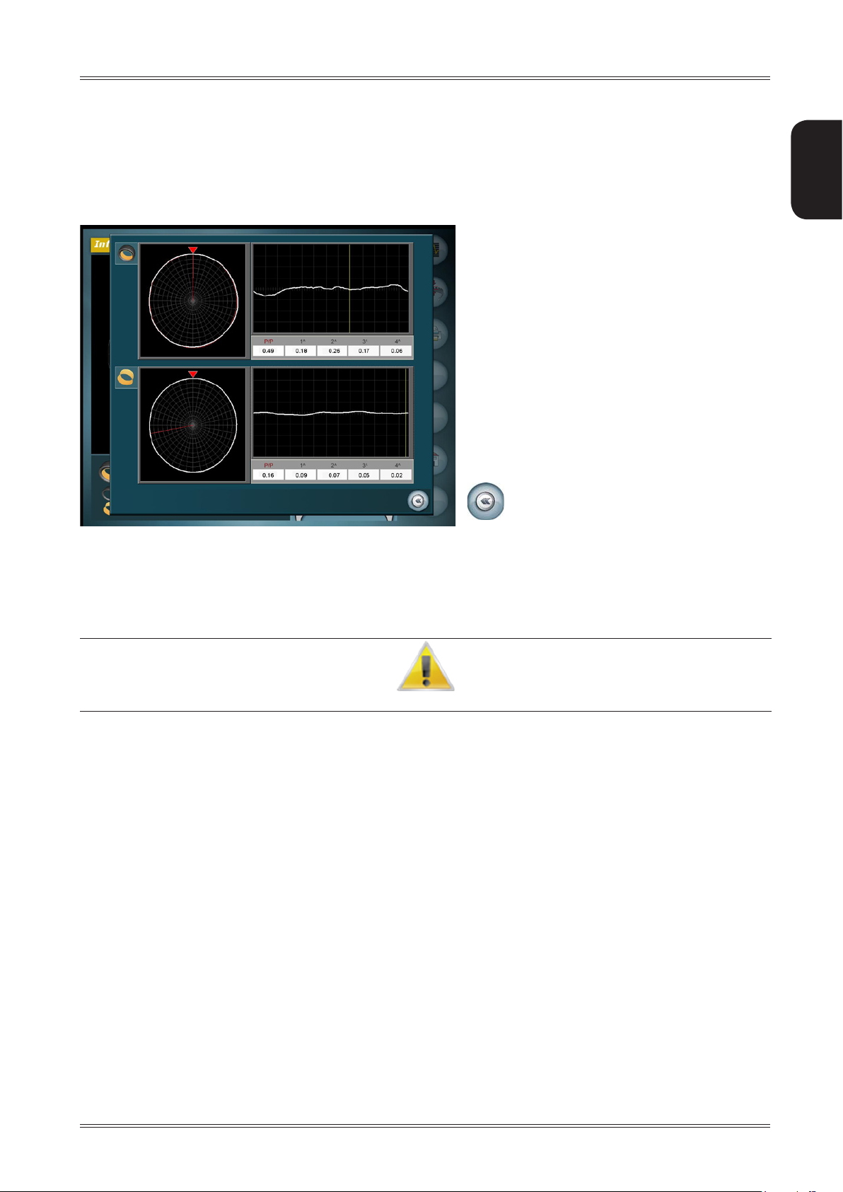
6.14.1.3 Peak/peak and first harmonic graphs
Goes back to the runout/matching analysis
screen
Displays the peak/peak, 1st, 2nd, 3rd, 4th harmonic graphs and values of the tyre and the rim.
Pressing on the graphs you can enlarge them to better highlight any wheel and rim defects.
yo u c A N d I s A b l e T h e W h e e l o R R I m e c c e N T R I c I T y m e A s u R e m e N T f R o m G e N e R A l s e T u p .
Use of the wheel balancing machine
Page 46

46
Use and Maintenance Manual Rev. 11-2011
ENGLISH
6.14.2 Tread
Goes to the peak/peak and first harmonic graph
screen.
Goes to the tread analysis screen
Prints the information screen
Return to main screen
Tread analysis can be performed
During the balancing cycle to obtain an average value measured over the whole tyre width. 1.
No extra time is required.
Enable a special measuring cycle using the button 2. to obtain the tread value for the three different areas:
inside edge, centre and outside edge of the tyre.
The cycle time is slightly longer.
By law (to be verified for each country) the minimum tread thickness must be 1.6mm at each point.
It is quite normal for tyres to wear irregularly and that the pivot pins wear more on one side.
By means of tread analysis at several points, you can measure the tyre tread depth with adequate accuracy on the
edges and in the centre.
Use of the wheel balancing machine
Page 47

47
Use and Maintenance Manual Rev. 11-2011
ENGLISH
For detailed tread analysis, press the button :
Increases the scale
Decreases the scale
Increases the scale
Decreases the scale
Enables cursor display for
tread measurement
Goes back to the information screen
When pressing the button two cursors are displayed (one red and one yellow) and a black window that shows
the difference in millimetres measured between the two cursors.
Dragging the cursors with your finger,
you can move them to another point
of the tread.
Goes back to the information screen
Indicates the distance between the
two cursors.
Use of the wheel balancing machine
Page 48

48
Use and Maintenance Manual Rev. 11-2011
ENGLISH
6.14.3 Taper
Goes to the peak/peak and first harmonic graph
screen.
Goes to the tread analysis screen
Prints the information screen
Return to main screen
Examination of the wheel taper requires a special measuring cycle to be enabled using the button and
requires a slightly longer cycle time.
After the measurement, you obtain:
GREEN indicator: wheel NOT TAPERED and in good conditions
YELLOW indicator: wheel SLIGHTLY TAPERED
to the right
or to the left
as indicated in the graph:
it is advisable to check the wheel soon.
RED indicator: TAPERED wheel
to the right
or to the left
as indicated in the graph.
Check the taper of the wheel to be mounted on the same axle, assess if there is any
toe-inor replace the wheel.
The wheel taper measurement is important to solve any vehicle drift problems. Wheels tapered in the same
direction and mounted on the same axle might lead to the vehicle having problems in maintaining the trajec-
tory on a straight line.
Use of the wheel balancing machine
Page 49

49
Use and Maintenance Manual Rev. 11-2011
ENGLISH
6.15 OUTSIDE RIM RUNOUT
mo u N T o N l y T h e R I m W I T h o u T T h e T y R e .
Press the button after closing the spindle.
Close the guard and press the button
Confirm
Goes back to the measurement screen
Return to main screen
Use of the wheel balancing machine
Page 50

50
Use and Maintenance Manual Rev. 11-2011
ENGLISH
The machine automatically reads the rim dimensions and performs a spin.
During rotation the outside eccentricity measurement is executed on the inner and outer edges of the rim in the positions laid down by the international standards.
When complete, a screen with the graphs of the values just measured is displayed.
Repeats the outside rim eccentricity measurement
Goes back to the measurement screen
Return to main screen
Identifies the rim outside
Identifies the rim inside
Outside rim runout within tolerance
Outside rim runout out of tolerance
Theoutsiderimrunoutmeasuredontheedgesoftherimisdeemedwithintoleranceifboththerstharmonic
and the peak/peak values measured are less than the limits set in OUTSIDE RIM RUNOUT setup
Use of the wheel balancing machine
Page 51

51
Use and Maintenance Manual Rev. 11-2011
ENGLISH
7. Wheel dismounting
Pu ▪ sh the Zero Weight pedal. The carriage moves up to the wheel retrieval position.
Push the tyre locking pedal to open the spindle. ▪
Push the Zero Weight pedal or push on the Zero Weight carriage lever to lower the carriage and dismount the ▪
wheel.
If T h e W h e e l h A s b e e N m o u N T e d W I T h o u T u s I N G T h e Ze R o We I G h T l I f T , p u s h I N G T h e Ze R o We I G h T p e d A l A N e R R o R m e s s A G e
W I l l b e d I s p l A y e d : d I s m o u N T T h e W h e e l W I T h o u T T h e A I d o f T h e l I f T I N T h e s A m e W A y I T W A s m o u N T e d .
Th e W h e e l m o u N T I N G /d I s m o u N T I N G o p e R A T I N G l o G I c I m p l I e s T h A T T h e W h e e l b e m o u N T e d A N d d I s m o u N T e d
u s I N G T h e l I f T A N d N o T b y h A N d .
Use of the wheel balancing machine
Page 52

52
Use and Maintenance Manual Rev. 11-2011
ENGLISH
8. Setup
8.1 MENU
Press the button from the measurement screen (second set of buttons)
Setup
Page 53

53
Use and Maintenance Manual Rev. 11-2011
ENGLISH
8.2 GENERAL SETUP
Gives the user the possibility of setting the machine according to need. All the settings remain
when the machine is turned off.
8.2.1 General setup 1/3
Decreases the value
Increases the value
Confirms the default parameters
Goes back to the main menu screen
Goes to the setup screen 2/3
Return to main screen
unaltered even
Language:
Screensaver (min.):
Screensaver type: allows customising the screensaver with any kind of image in .jpg format. ( SCREEN-
Linear unit of measure: selects the unit of measure (mm/inch)
Correction method: allows selecting from 3 correction methods: STANDARD, EXTERNAL PLANES, BPC
STANDARD The wheel balancing machine considers the unbalance within tolerance when the value of
EXTERNAL PLANES The unbalance is considered within tolerance when the weight recalculated on the external
allows selecting the language to be used to display the descriptive and diagnostic messages
relating to machine operation.
allows selecting when the screensaver will be activated after the machine has not been
used for a certain time.
SAVER CUSTOMISATION)
each single plane is lower than the tolerance set.
planes (clip-on weight) is lower than the tolerance set.
Setup
Page 54

54
Use and Maintenance Manual Rev. 11-2011
ENGLISH
BPC (Best Possible Correction) Provides the best possible solution for reduction of vibrations noticeable in the
vehicle.
Many elements affect the vibration perceived in the vehicle due to wheel unbalances:
Residual static unbalance
▪
Residual dynamic (or torque) unbalance
▪
Wheel weight (the heavier the wheel, the less the unbalance will make it vibrate)
▪
Wheel diameter (on which the application radiuses of the counterweights depend)
▪
Comparison between conventional balancing and the BPC method
CONVENTIONAL BALANCING:
Given a set tolerance of 5g, a wheel is considered balanced also with a residual unbalance of 4.9g per plane in
▪
approximately the same angular position. This means that a static unbalance of 9.8 grams is tolerated, even
though the static unbalance is deemed the main cause of vibrations noticeable by the driver.
The balancing tolerance for all wheel types, not taking any unbalance of 10g into account, produces different
▪
vibrations on a 13” or a 22" wheel. The residual vibrations are inversely proportional to the wheel weight.
The angular position of the residual unbalances is not taken into account.
▪
BALANCING USING THE BPC METHOD:
With this method, the balancing tolerance value is reprocessed based on the wheel dimensions and the permissible ▪
residual static and torque unbalances, which are numerically different (greater torque unbalance than static
unbalance is permitted).
The tolerance no longer refers to the correction planes but is UNIQUE and indicates the residual vibration limit
▪
value permissible on the wheel.
An indicator on the screen provides information on the residual vibration obtained after balancing with respect
▪
to the maximum tolerable vibration.
Bymeans of complex mathematical calculations, it indicates how many and where correction weights should be
▪
added for the best possible reduction of the vibrations noticeable by the driver. This means that the customer
receives the best possible service.
No alternative method can be more accurate, using moderate weights with steps of 5g.
The machine also measures by HOW MUCH the “noticeable vibration” in the vehicle has been reduced with respect to the
conventional method, indicating the percentage reduction, i.e. by how much it has improved with respect to conventional
machines.
Less vibration, more satised customers!
Display pitch: This represents the unbalance display pitch and varies based on the unit of measure
selected.
such as to set the static unbalance value to 0 (theoretical).
It is advisable to set this function for normal use of the machine, as it improves the
ancing quality. The computer makes a complex calculation
residual static unbalance by varying the value and the position of the counterweights xed
in steps of 5 grams (1/4 oz).
Tolerance
Default parameter setting: Resets the default machine settings.
:
This is the unbalance threshold below which OK appears on the screen instead of the
unbalance value at the end
Selecting 5g (1/4 oz) enables display of the correction values
which allows cancelling the
of the spin.
on the two sides
bal-
Setup
Page 55

55
Use and Maintenance Manual Rev. 11-2011
ENGLISH
8.2.1.1 Screensaver customisation
From the General Setup screen, select CUSTOMISED SCREENSAVER and press the button
CUSTOMISED
SCREENSAVER
Saves the current screensaver to the USB key. The directory Screensave is created on the key
containing the file screensave.jpg; replace this file with the desired image, keeping the same name and
the same format (.jpg)
Loads the customised screensaver to the machine.
Setup
Goes directly to the screensaver screen.
Goes back to the general setup screen
Page 56

56
Use and Maintenance Manual Rev. 11-2011
ENGLISH
8.2.2 General setup 2/3
Decreases the value
Increases the value
Confirms the default parameters
Goes back to the setup screen 1/3
Goes to the setup screen 3/3
Return to main screen
Static unbalace always present: Enables/disables temporary display of the unbalance on the correction planes
selected and the STATIC unbalance
Wheel locking: Enables/disables wheel locking in the correction position
Wheel runout: Enables/disables wheel eccentricity measurement
Rim runout: Enables/disables rim eccentricity measurement
Runout diagnosis: Enables/disables display of the runout values on the unbalance measurement
screen
Lift: Enables/disables the lift
Printer: Enables/disables the printer
Tyre set: Enables/disables the tyre set function
Default parameter setting: Resets the default machine settings
Setup
Page 57

57
Use and Maintenance Manual Rev. 11-2011
ENGLISH
8.2.3 General setup 3/3
Decreases the value
Increases the value
Confirms the default parameters
Goes back to the setup screen 2/3
Return to main screen
Rim interior light: Enables/disables a light to come on when the wheel is in the correction
position
Anticipated laser movement: Enables/disables anticipated laser movement as soon as you start closing
the guard.
If disabled, the lasers start measuring the wheel dimensions only after
having completely closed the guard.
Vibration reduction display: Enables/disables display of the vibration reduction percentage of the BPC
method with respect to the conventional method.
Functions only if the BPC method is enabled.
Default parameter setting: Resets the default machine settings
Status icon: enables/disables display of status icons on the main screen
Positioning: enables/disables wheel positioning.
Setup
Page 58

58
Use and Maintenance Manual Rev. 11-2011
ENGLISH
8.3 RESERVED SETUP
Access to this screen is password protected [1 - 3 - 5 - 7 ].
Press to access to reserved setup second screen.
IN c o R R e c T l y c A R R y I N G o u T T h e R e s e R v e d s e T u p p R o c e d u R e s m I G h T c A u s e s e R I o u s p R o b l e m s W I T h W h e e l b A l A N c I N G A N d d I A G N o s I s .
Reserved Setup
Page 59

59
Use and Maintenance Manual Rev. 11-2011
ENGLISH
8.3.1 LASER calibration
Saves the laser calibration values
Confirm
Goes back to the measurement screen
Return to main screen
Open the spindle and fit the specific calibration tool as shown in the figure.1.
Th e T o o l c A N N o T b e f I T T e d I N A p o s I T I o N d I f f e R e N T f R o m T h A T I N d I c A T e d I N T h e f I G u R e .
do N o T p e R f o R m A b A l A N c I N G s p I N W I T h T h e c A l I b R A T I o N T o o l f I T T e d .
Al W A y s f I T T h e c A p o N T h e c o l l A R .
Close the spindle and the guard and press the 1. button.
Re2. move the calibration tool and press
Press 3. to save the calibration
Press 4. to exit from the screen.
Reserved Setup
Page 60

60
Use and Maintenance Manual Rev. 11-2011
ENGLISH
8.3.2 CC motor calibration
Lock the spindle without a wheel or tools mounted. Close the guard and press 1.
Wait for the procedure to complete.2.
If erroneously accessing the fun3. ction, press
To i4. nterrupt the procedure, press .
Reserved Setup
Page 61

61
Use and Maintenance Manual Rev. 11-2011
ENGLISH
8.3.3 Spindle reset
Resets the spindle reset values.
Displays the spindle reset values saved
Saves the spindle reset values.
Confirm
Goes back to the measurement screen
Return to main screen
Lock the spindle without a wheel or tools. Close the guard and press the button 1.
View the spindle reset values just read 2. (if necessary for particular tests requested by Technical Service).
Pr3. ess to save the spindle reset values
Press 4. to exit from the screen.
Reserved Setup
Page 62
62
Use and Maintenance Manual Rev. 11-2011
ENGLISH
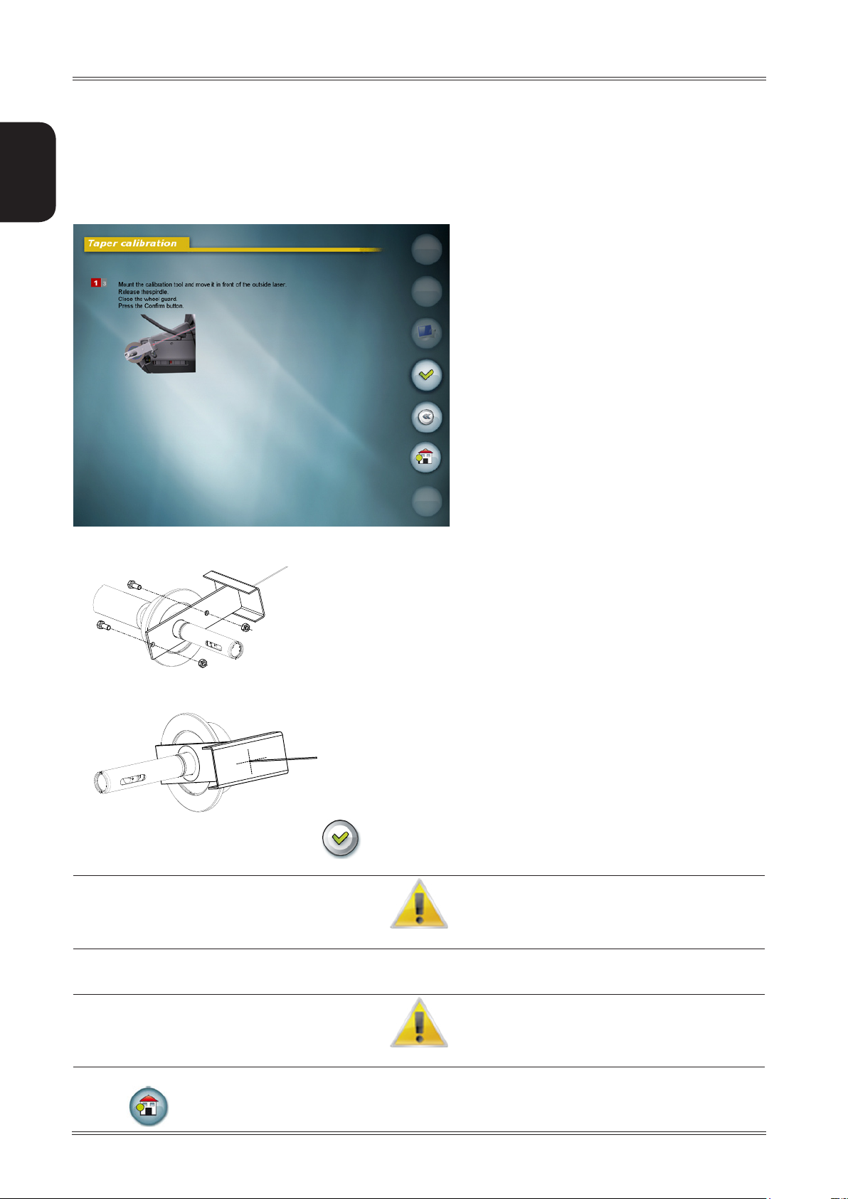
8.3.4 Taper calibration
Saves the calibration
Confirm
Goes back to the reserved setup screen
Return to main screen
Open the spindle and fit the calibration tool fastening it to the adapter with the screw and nut provided. 1.
Position the tool in such a way that the laser crosses its central part during normal reading movement.2.
C3. lose the guard and press the button
When prompted on the screen, remove the tool and then fit it on the other side.4.
do N o T o p e N T h e s p I N d l e .
When reading is complete, remove the calibration tool.5.
dA N G e R ! do N o T p e R f o R m A s p I N W I T h T h e T o o l f I T T e d !
6. Save the calibration.
7. Press to go back to the main screen.
Reserved Setup
Page 63

63
Use and Maintenance Manual Rev. 11-2011
ENGLISH
8.3.5 Correction weights
Decreases the value
Increases the value
Displays a calculator to
enter values directly
Confirms the default parameters
Goes back to the reserved setup screen
Return to main screen
Correctly set the length of the correction weights in order to improve the balancing quality.
Default parameter setting: Resets the default machine settings.
The zinc weights used for balancing generally become very long as the weight increases; in this condition the
weight can no longer be considered concentrated at the barycentre and the effect, for example, is a weight of
only 47 instead of 50 grams.
Correctly setting the length of the correction weights allows the wheel balancing machine to automatically compensate for the fact that all the weight cannot be applied at one point.
Reserved Setup
To o b T A I N T h e b e s T R e s u l T s , A l W A y s u s e W e I G h T s o f T h e s A m e m A N u f A c T u R e R .
Page 64

64
Use and Maintenance Manual Rev. 11-2011
ENGLISH
8.3.6 Wheel runout
Decreases the value
Increases the value
Confirms the default parameters
Goes back to the reserved setup screen
Return to main screen
Wheel first harmonic limit: Represents the first harmonic limit beyond which it is considered appropriate
to turn the tyre on the rim by 180°. Recommended limit = 1.2 mm.
Rim first harmonic limit: Represents the first harmonic limit of the rim below which it is not considered
appropriate to turn the tyre on the rim.
Recommended limit = 0.3 mm.
Minimum correction limit: Represents the minimum correction limit obtainable below which it is not
considered appropriate to turn the tyre on the rim. Recommended limit =
0.8 mm.
Default parameter setting: Resets the default machine settings.
Reserved Setup
Page 65

65
Use and Maintenance Manual Rev. 11-2011
ENGLISH
8.3.7 Outside rim runout
Decreases the value
Increases the value
Confirms the default parameters
Goes back to the reserved setup screen
Return to main screen
Outside rimrunout: Enables/disables the outside rim runout measurement function
Inside first harmonic limit: Represents the threshold beyond which the first harmonic value read for
the rim inside is not considered acceptable.
Outside first harmonic limit: Represents the threshold beyond which the first harmonic value read for
the rim outside is not considered acceptable.
Inside peak/peak limit: Represents the threshold beyond which the peak/peak value read for the
rim inside is not considered acceptable.
Outside peak/peak limit: Represents the threshold beyond which the peak/peak value read for the
rim outside is not considered acceptable.
Default parameter setting: Resets the default machine settings.
Reserved Setup
Page 66

66
Use and Maintenance Manual Rev. 11-2011
ENGLISH
8.3.8 Tread
Decreases the value
Increases the value
Confirm
Goes back to the reserved setup screen
Return to main screen
Tread limit: Represents the threshold beyond which the tread is no longer acceptable.
Default parameter setting: Resets the default machine settings.
Reserved Setup
Page 67

67
Use and Maintenance Manual Rev. 11-2011
ENGLISH
8.3.9 Reserved for technical service
Password-protected area reserved for technical service only.
Ac c e s s T o T h I s A R e A W I T h o u T T h e N e c e s s A R y K N o W l e d G e m I G h T l e A d T o INcoRRecT f u N c T I o N I N G A N d e v e N m A T e R I A l d A m A G e T o T h e
W h e e l b A l A N c I N G m A c h I N e .
8.3.10 Saves the machine calibration
Saves the machine calibration values to key.
8.3.11 Loads the user manual
Allows loading manuals in languages different from that loaded in the machine.
Reserved Setup
Page 68
68
Use and Maintenance Manual Rev. 11-2011
ENGLISH
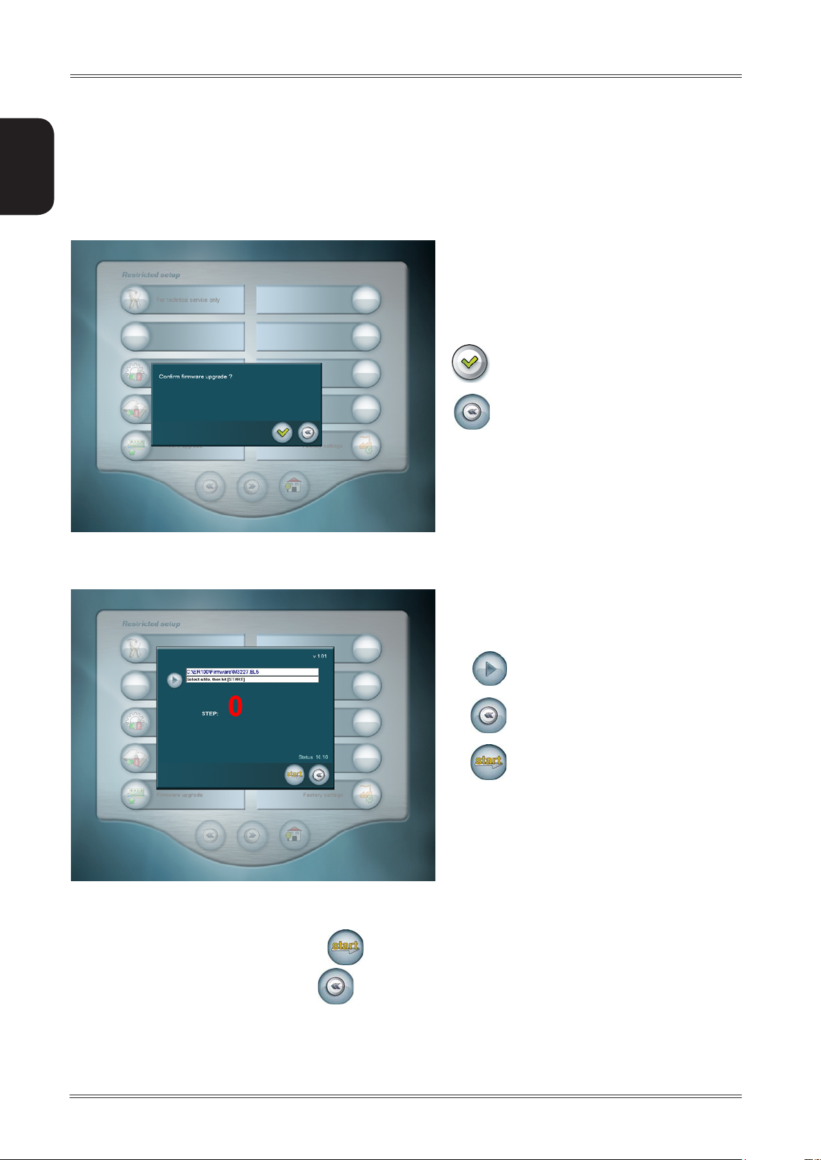
8.3.12 Firmware upgrade
Allows updating the board firmware.
Confirms access to the function
Goes back to the reserved setup screen
Press the Confirm button1.
2. Press the Browse Folders button to select the new firmware.
3. Select the file .BL5 and press the button
Browse folders
Goes back to the reserved setup screen
Starts the firmware upgrade
4. When the operation is complete, press to exit the function.
Reserved Setup
Page 69

69
Use and Maintenance Manual Rev. 11-2011
ENGLISH
8.3.13 Factory setting
Confirms loading of the factory settings
Goes back to the reserved setup screen
Return to main screen
Restore all the default settings of the machine, including the instruction manual in English.
ex e c u T e T h I s f u N c T I o N o N l y W h e N R e q u e s T e d b y s p e c I A l I s e d p e R s o N s .
Reserved Setup
Page 70

70
Use and Maintenance Manual Rev. 11-2011
ENGLISH
8.4 MACHINE CALIBRATION
Saves the calibration values
Confirm
Goes back to the setup screen
Return to main screen
Dismount any wheel from the wheel balancing machine, close the spindle and the guard and press the button 1.
Open the guard, fit the calibration tool on the outside of the adapter (as shown in the figure), close the guard and 2.
press
Open the guard, fit the calibration tool on the inside of the adapter (as shown in the figure) in the same hole used 3.
for the previous spin, close the guard and press
Move the tool to the top at 12 o’clock and press the button 4.
Press the button 5. .
Re m o v e T h e c A l I b R A T I o N T o o l ; p e R f o R m I N G A b A l A N c I N G s p I N W I T h T h e c A l I b R A T I o N T o o l f I T T e d o N T h e I N s I d e m I G h T c A u s e s e R I o u s
d A m A G e T o T h e I N T e R N A l l A s e R .
6. Press to exit from the screen.
Reserved Setup
Page 71

71
Use and Maintenance Manual Rev. 11-2011
ENGLISH
8.5 DIMENSIONS
Allows accessing the manual wheel dimension setting screen.
TEST s c R e e N R e s e R v e d f o R e x p e R T s .
us e o N l y IN s p e c I f I c c A s e s .
Reserved Setup
Page 72

72
Use and Maintenance Manual Rev. 11-2011
ENGLISH
8.6 SELF-DIAGNOSTICS
Automatic measuring cycle
Laser reset
Diagnosis parameter printout useful for Technical Service.
Goes back to the main menu screen
Return to main screen
Displays a screen containing numerous test parameters useful for the maintenance technician.
Enables an automatic unbalance and runout cycle useful to check any machine oscillation problems.
Execute this function only on specific request of Technical Service.
Enables a laser reset cycle, to be executed only on specific request of Technical Service.
Reserved Setup
Page 73

73
Use and Maintenance Manual Rev. 11-2011
ENGLISH
8.7 OSK
Allows correctly setting the date and time.
Increases the value
Decreases the value
Confirm
Goes back to the main menu screen
Press the button to go to date setting.
Increases the value
Decreases the value
Confirms and goes back to the main
menu screen
Goes back to the main menu screen
Reserved Setup
Page 74

74
Use and Maintenance Manual Rev. 11-2011
ENGLISH
8.8 SOUNDS
Decreases the value
Increases the value
Confirms the default parameters
Goes back to the main menu screen
Return to main screen
Introduction: Enables/disables an introduction sound during machine power on.
Touch buttons: Enables and selects/disables the sound emitted when pressing any button
se v e R A l T y p e s o f s o u N d A R e A v A I l A b l e ; s e l e c T T h e o N e y o u l I K e T h e m o s T .
Wheel in position:
Default parameter setting: resets the default machine settings.
Enables/disables the sound emitted when the wheel is in the correction position
8.9 INSTRUCTION MANUAL
Displays the machine instruction manual .
Reserved Setup
Page 75

75
Use and Maintenance Manual Rev. 11-2011
ENGLISH
9. Diagnostics
Th e I N f o R m A T I o N I N T h e possIble Remedy c o l u m N R e q u I R e s W o R K T o b e p e R f o R m e d b y s p e c I A l I s T T e c h N I c I A N s o R o T h e R A u T h o R -
WARNING
I s e d p e o p l e W h o m u s T A l W A y s W o R K u s I N G T h e pe R s o N A l pR o T e c T I v e eq u I p m e N T I N d I c A T e d I N T h e INsTAllATIoN m A N u A l . IN s o m e
SOFTWARE
ERRORS
Black The wheel balancing machine does not
Err. 1 STOP button pressed with the motor
Err. 2 Speed too low during measurement.
Err. 3 Unbalance too high. 1. Check the wheel dimensions setting.
Err. 5 Guard open.
Err. 6 Spindle open
Err. 8 Errorintransferoftheoutsideprole
Err. 9 Errorintransferoftheinsideprole
Err. 10 The inside adhesive weight distance is
Err. 11 Speed too high error.
Err.15 Error. Dimensions stored invalid 1. Repeat the wheel dimension measurement.
Err. 16 Internal laser position error during the
CAUSE POSSIBLE REMEDY
switch on.
running.
During the unbalance measurement
spins, the wheel speed dropped to
below 42 rpm.
Guard opening during the measuring
cycle
Spinenabledwithoutrsthavingclosed
the spindle.
measurement data from the computer
board to the PC.
measurement data from the computer
board to the PC.
greater than the outside adhesive weight
distance.
During unbalance measurement rotation, wheel speed is more than 270 rpm.
machine calibration function.
c A s e s , T h I s W o R K c A N b e p e R f o R m e d b y A N o R m A l o p e R A T o R .
1. Check the machine is properly connected to the mains power supply.
2. Check the fuses on the power board and replace if necessary.
3. Check display functioning.
4. Replace the PC.
1. Reset the error.
2. Repeat the spin.
Make sure that a vehicle wheel is mounted on the wheel balancing 1.
machine.
Use the self-diagnostics function to check the encoder.2.
Disconnect the measuring head connector from the board and perform 3.
a spin (if there is no error, replace the measuring heads)
Replace the computer board.4.
2. Check the detection unit connections.
3. Run the machine calibration function.
4. Mountawheelwithamoreorlessknownunbalance(denitely less
than 100 grams) and check the response of the machine.
5. Replace the computer board.
1. Reset the error
2. Check functioning of the protection switch
3. Close the guard.
1. Reset the error
2. Close the spindle
3. Lower the guard
1. Repeattheoutsideprolemeasurement.
2. Replace the computer board.
1.Repeattheinsideprolemeasurement.
2. Replace the computer board.
1. Repeat the wheel dimension measurement.
2. Repeat the laser calibration function.
3. Replace the computer board.
1. Use the self-diagnostics function to check the encoder.
2. Replace the computer board.
2. Use the self-diagnostics function to check proper functioning of the
lasers.
3. Replace the computer board
1. Check that the internal laser is in the rest position.
2. Use the self-diagnostics function to check proper functioning of the
internal laser.
3. Check proper functioning of the switch that detects the internal laser
in rest position.
4. Access the machine calibration function with the laser only
Diagnostics
Page 76

76
Use and Maintenance Manual Rev. 11-2011
ENGLISH
Err. 20 Message management error (incorrect
Err.21 Date and time setting error
or no translations)
Err. 31/
Err. 32/
Err. 33/
Err. 34/
Err. 39/
Err. 42
Err.50 Error in eccentricity measurement using
Err.51 Error in eccentricity measurement using
Err.70 Error. Lift down and does not ascend.
Err.71 Error. Lift up and does not descend.
Err.72 Error. Lift up during unbalance,
Err. 121/122
Err. 123/124
Err. 125/126
Err. 127/128
Err. 129/130
Err. 131/132
Err. 133
Err. 141/142
Err. 143/144
Err. 145/146
Err. 147/148
Err. 149/150
Err. 151/152
Err. 153
Err.201 Lasercalibrationlewriteerror 1. Repeat the laser calibration function.
Err.202 Laser calibration incorrect or inexistent 1. Repeat the laser calibration function.
Firmware upgrade management error.
the external laser
the internal laser
eccentricity and taper measurement
Internal laser motor control error. 1. Reset the wheel balancing machine.
External laser motor control error. 1. Resetthe wheel balancing machine.
1. Change the language, selectable in Setup.
2.ContactTechnicalServicetondoutiftheon-screenmessagescan
be updated in the various languages.
1. Repeat the date and time setting function.
2. Check that you have set numbers compatible with the date and time
format.
1. CheckthatyouhaveloadedalewithextensionBI5.
2. Repeatthermwareupgradefunction.
1. Check that you have correctly mounted the wheel or rim.
2. Repeat the eccentricity measurement function.
1. Check that you have correctly mounted the wheel or rim.
2. Repeat the eccentricity measurement function.
1.
Use the self-diagnostics function to check proper functioning of the lift.
2.
Check proper functioning of the switch that detects the lift in rest position.
1.
Use the self-diagnostics function to check proper functioning of the lift.
2.
Check proper functioning of the switch that detects the lift in rest position.
1. Lower the lift before starting any measuring cycle
2. Contact Technical Service.
2. Contact Technical Service.
Err.203 Error in reading the laser calibration tool. 1.Checkthatyouhavecorrectlyttedthelasercalibrationtool.
Err. 204/
Err. 205/
Err. 208/
Err. 209
Err. 206 External laser read error (during
Err. 207 External laser read error (during
Err. 211/
Err. 212/
Err. 213/
Err. 214
Error in the data read for laser
calibration.
calibration).
calibration).
External laser read error 1. Check that the light spot is visible on the wheel to be measured.
2. Check that the laser light spot is able to read the calibration tool.
3. Repeat the laser calibration function.
1. Repeat the laser calibration function.
1. Check that the external laser light spot is able to read the spindle and
the calibration tool.
2. Repeat the laser calibration function.
1.Checkthatyouhavecorrectlyttedthecalibrationtool.
2. Check that there are no objects that may interfere with calibration tool
reading.
3. Repeat the laser calibration function.
2. Check that you have correctly mounted the wheel to be balanced.
3. Check that there are no objects other than the wheel in the laser
measuring range.
4. Repeat the dimension measurement.
Diagnostics
Page 77

77
Use and Maintenance Manual Rev. 11-2011
ENGLISH
Err. 221/
Err. 222/
Err. 223/
Err. 224/
Err. 225
HARDWARE
ERRORS
Err.2 Hardware error from acquisition board. ---
Code 21 Error. Guard open during measurement. 1. Repeat the measurement keeping the guard closed until the end of the
Code 22 STOP during a measuring cycle. 1. Repeat the measuring cycle avoiding to press the STOP button unless
Code 23 Error. Lift position during the measuring
Code 24 Pneumatic spindle released during the
Code 25 Rotation start timeout. 1. Check that there are no obstructions to normal wheel rotation.
Code 26 Wheel braking timeout 1. Check functioning of the power board relay
Code 27 Inverse rotation. 1. Use the self-diagnostics function to check the encoder.
Code 28 Unbalance measurement timeout. 1. Repeat the unbalance measuring cycle.
Code 29 Eccentricity measurement timeout. 1. Repeat the eccentricity measuring cycle.
ERRORS
HARDWARE
TYPE
Err.3 Software error from acquisition board. ---
Internal laser read error 1. Check that the light spot is visible on the wheel to be measured.
CAUSE CHECKS
cycle.
measuring cycle.
CAUSE CHECKS
2. Check that you have correctly mounted the wheel to be balanced.
3. Check that there are no objects other than the wheel in the laser
measuring range.
4. Repeat the dimension measurement.
spin.
for an emergency.
1. Enable the measuring cycle only when the lift is in rest position.
2. Do not move the lift during the measuring cycle.
1. Lock the wheel before starting the measuring cycle.
2. Do not move the lift during the measuring cycle.
2. Use the self-diagnostics function to check the encoder.
3. Use the self-diagnostics function to check proper functioning of the
electromagnetic switch.
4. Check functioning of the power board relay
2. Check functioning of the power board relay
2. Contact Technical Service.
2. Contact Technical Service.
Code: all Congurationparametersettingerrors
ERRORS
HARDWARE
TYPE
Err.128 Ethernet error. ---
Code: all Communication errors via Ethernet
Unbalance
incorrect with
back centring
cones
from the PC to the computer board.
CAUSE CHECKS
between the PC and the acquisition
board.
Wheel slipping on the adapter because
the BP system is at the end of travel or
becauseofincorrectttingofthetyre
tie-rod
1. Turn the wheel balancing machine off and on again.
2. Contact Technical Service.
1. Turn the wheel balancing machine off and on again.
2. Check the Ethernet connection cables between the PC and the
acquisition board.
3. Replace the acquisition board.
Mount the wheel in vertical position and push the sleeve up against the
wheel. If necessary, repeat locking/unlocking/locking and perform the
procedure again.
Diagnostics
Page 78

78
Use and Maintenance Manual Rev. 11-2011
ENGLISH
10. Maintenance
10.1 GENERAL
cAuTIoN
be f o R e p e R f o R m I N G A N y m A I N T e N A N c e o p e R A T I o N s , m A K e s u R e
T h e m A c h I N e h A s b e e N d I s c o N N e c T e d f R o m T h e m A I N s p o W e R
s u p p l y . Al W A y s u s e T h e pe R s o N A l pR o T e c T I v e eq u I p m e N T
I N d I c A T e d IN T h e IN s T A l l A T I o N mA N u A l .
10.1.1 Introductory notes
This machine has been designed so as not to require routine maintenance, apart from accurate periodic cleaning.
It is important to keep the machine perfectly clean in order to prevent dust or impurities from compromising the
operation of the balancer.
Specialist staff must be authorised and especially trained
concerning the dangers that may arise during operation
and the correct methods for avoiding them.
They must always work with great care and pay full attention.
If, exceptionally, the staff removes the guards to carry out
a particular specialist technical maintenance, inspection
or repair job, they are required to put them back after
work.
After work, staff must make sure that foreign objects, in
particular mechanical pieces, tools or devices used during the operative procedure that could cause damage or
malfunctions are not left inside the balancer.
For safety, before starting work, maintenance, inspection
and repair staff must disconnect all power sources and
take all the necessary preventive safety measures.
As well as operating frequencies, the operations described
below indicate the qualifications that staff must possess
in order to perform the operation.
10.1.3 Replacing fuses
Th e p e o p l e R e s p o N s I b l e f o R c l e A N I N G T h e A R e A W h e R e T h e
WARNING
m A c h I N e Is I N s T A l l e d m u s T W e A R p e R s o N A l p R o T e c T I v e e q u I p m e N T
IN o R d e R T o W o R K I N s A f e T y A N d A c c o R d I N G T o T h e c u R R e N T
o c c u p A T I o N A l h e A T h A N d s A f e T y R e G u l A T I o N s .
As extraordinary maintenance must be performed by service
staff or, in any case, by specifically authorised and trained
people, is not dealt with in this manual.
10.1.2 Safety rules
Performing specialist activities on the equipment, particularly if the guards need to be dismounted, exposes people
to serious danger due to the presence of potentially live
parts.
The rules shown below must be scrupulously followed.
People must always use the Personal Protective Equipment indicated in the Installation Manual. During activities, unauthorised people may not access the equipment
and WORK IN PROGRESS signs will be erected in the
department in such a way that they are visible from every
place of access.
Some protection fuses are located on the power board
(see wiring diagrams) accessible by dismantling the weight
shelf). If fuses require replacement, use ones with an
identical current intensity.
10.1.4 Periodic cleaning
cAuTIoN
The touch panel and the external scanning laser efficiency
can be guaranteed using a soft cloth and NON-ABRASIVE
commercial glass/plastic cleaning spray or ethanol or
natural detergents.
DO NOT USE:
Organic solvents type nitro thinner
Turpentine
Petrol
Trichloroethylene
Acetone
Maintenance
Page 79

79
Use and Maintenance Manual Rev. 11-2011
ENGLISH
11. Disposal
cAuTIoN
Th e I N s T R u c T I o N s IN T h I s c h A p T e R A R e I N d I c A T I v e . Re f e R T o
T h e R e G u l A T I o N s I N f o R c e I N T h e c o u N T R y W h e R e T h e e q u I p -
m e N T I s u s e d .
11.1 DISPOSING OF THE BALANCER
The balancer must be disposed of after dismounting the
various parts.
For disposal operations, as well as wearing the Personal
Protective Equipment indicated in the INSTALLATION
MANUAL, refer to the instructions and diagrams in this
manual. If necessary, request specific information from
the manufacturer.
Once you have removed the various parts and components,
separate them into the different types of materials according
to the differentiated waste disposal regulations in force in
the country where the machine is dismantled.
12. Spare parts
12.1 IDENTIFICATION AND ORDERING
METHOD
The various parts can be identified using the explodeddrawings, the electrical drawings and diagrams in the machine
technical file which is archived by the Manufacturer to
which a request can be made.
For off-the-shelf parts, the technical manuals or the supplier’s original documents can be provided if the Manufacturer deems this to be useful.
If not supplied, this documentation is also included in the
machine Technical File, archived by the Manufacturer, as
regards by Ministerial Decree 98/37/EC.
In this case, contact the Technical Service to identify the
required piece.
If the required pieces are not in any position or they can-
not be identified, contact the Technical Service, specifying the type of machine, its serial number and year of
construction.
This information is indicated on the machine identification plate.
If the various components must be stored before being
taken to the dump, make sure to keep them in a safe place
protected from atmospheric agents in order to prevent them
from contaminating the ground and the water table.
11.2 DISPOSING OF ELECTRONICS
COMPONENTS
Community directive 2002/96/EC, assimilated
in Italy with legislative decree n° 151 of 25th
July 2005, requires electrical and electronic
equipment manufacturers and users to comply
with a number of obligations concerning the
collection, treatment, recovery and disposal
of this waste.
Please scrupulously comply with these waste disposal
regulations.
Remember that abusive dumping of this waste leads to
the application of the administrative penalties established
by current law.
13. Attached
documentation
If not supplied, this documentation is included in the Technical File of the machine, archived by the Manufacturer.
In this case, contact the Technical Service for detailed
information concerning the machine.
Disposal – Spare parts – Attached documents
Page 80

 Loading...