


Carrier 48ZT, 48ZG, Z6, ZN030-105, ZW User Manual 2
...WEATHERMASTER® 48ZG,ZN030-105 48ZT,ZW,Z6,Z8075-105
Single Package Gas Heating and Electric Cooling Units with Direct Spark Ignition and COMFORTLINK™ Controls
Installation Instructions
CONTENTS
Page
GENERAL . . . . . . . . . . . . . . . . . . . . . . . . . . . . . . . . . . . . . . . . 1
SAFETY CONSIDERATIONS . . . . . . . . . . . . . . . . . . . . .1,2
INSTALLATION . . . . . . . . . . . . . . . . . . . . . . . . . . . . . . . . 2-59
Jobsite Survey . . . . . . . . . . . . . . . . . . . . . . . . . . . . . . . . . . . 2
Unit Placement. . . . . . . . . . . . . . . . . . . . . . . . . . . . . . . . . . . 2
Roof Mount . . . . . . . . . . . . . . . . . . . . . . . . . . . . . . . . . . . . . . 2
Slab Mount. . . . . . . . . . . . . . . . . . . . . . . . . . . . . . . . . . . . . . . 2
Curb Gasketing . . . . . . . . . . . . . . . . . . . . . . . . . . . . . . . . . . 2
Field-Fabricated Ductwork . . . . . . . . . . . . . . . . . . . . . . . 2
Rigging . . . . . . . . . . . . . . . . . . . . . . . . . . . . . . . . . . . . . . . . . . 2
Condensate Drain Connections . . . . . . . . . . . . . . . . . 23
Install Outdoor Hoods
(48ZG,ZN,Z6,Z8 Units). . . . . . . . . . . . . . . . . . . . . . . . . 33
•UNIT SIZES 030-050
•UNIT SIZES 055-105
Install Economizer Hoods (48ZT,ZW Units) . . . . . . 35
•INSTALL SMALL HOODS
•INSTALL LARGE HOODS
Field Wire Routing . . . . . . . . . . . . . . . . . . . . . . . . . . . . . . 36
•UNIT SIZES 030-050
•UNIT SIZES 055-105
Field Electrical Connections . . . . . . . . . . . . . . . . . . . . 36
• POWER WIRING
Air Pressure Tubing . . . . . . . . . . . . . . . . . . . . . . . . . . . . . 51
•INLET GUIDE VANES
•VARIABLE FRQUENCY DRIVE
•MODULATING POWER EXHAUST
•RETURN/EXHAUST POWER EXHAUST
Supply-Fan Shipping Brackets . . . . . . . . . . . . . . . . . . 53
•UNIT SIZES 030-050
•UNIT SIZES 055-070
•UNIT SIZES 075-105
Return/Exhaust Fan Shipping Brackets
(48Z6,Z8 Units). . . . . . . . . . . . . . . . . . . . . . . . . . . . . . . . 53
Remove TXV Shipping Blocks. . . . . . . . . . . . . . . . . . . 54
Compressor Mounting . . . . . . . . . . . . . . . . . . . . . . . . . . 55
Gas Piping . . . . . . . . . . . . . . . . . . . . . . . . . . . . . . . . . . . . . . 55
Optional Staged Gas Control . . . . . . . . . . . . . . . . . . . . 55
Installing Flue/Inlet Hoods . . . . . . . . . . . . . . . . . . . . . . 56
Supply Air Thermistors
(Staged Gas Units Only) . . . . . . . . . . . . . . . . . . . . . . 56
Install Unit Accessories . . . . . . . . . . . . . . . . . . . . . . . . . 59
CONTROLS INSTALLATION . . . . . . . . . . . . . . . . . . 59-66
Constant Volume Units. . . . . . . . . . . . . . . . . . . . . . . . . . 59
• CONTROL WIRING
Variable Air Volume Units . . . . . . . . . . . . . . . . . . . . . . . 59
Optional and Accessory Control Wiring . . . . . . . . . 60
Carrier Comfort Network® (CCN) Interface. . . . . . . 60
Smoke Control Modes. . . . . . . . . . . . . . . . . . . . . . . . . . . 61
GENERAL
This installation instruction contains basic unit installation information, including installation of thermostats and remote temperature sensors.
For additional information and service instructions, refer to the Controls and Troubleshooting literature also enclosed in this literature packet.
The 48ZT,ZW units are equipped with standard integral economizer and high-capacity power exhaust.
The 48Z6,Z8 units are equipped with factory-installed return/exhaust fans.
The staged gas control (SGC) option adds the capability to control the rooftop unit’s gas heating system to a specified supply air temperature set point for purposes of tempering a cool mixed-air condition.
SAFETY CONSIDERATIONS
Installation and servicing of air-conditioning equipment can be hazardous due to system pressure and electrical components. Only trained and qualified service personnel should install, repair, or service air-conditioning equipment.
Untrained personnel can perform basic maintenance functions of cleaning coils and filters and replacing filters. All other operations should be performed by trained service personnel. When working on air-conditioning equipment, observe precautions in the literature, tags and labels attached to the unit, and other safety precautions that may apply.
Follow all safety codes, including ANSI (American National Standards Institute) Z223.1. Wear safety glasses and work gloves. Use quenching cloth for unbrazing operations. Have fire extinguisher available for all brazing operations.
 WARNING
Before performing service or maintenance operations on unit, turn off main power switch to unit. Electrical shock could cause personal injury.
FOR YOUR SAFETY
WHAT TO DO IF YOU SMELL GAS
Do not try to light any appliance. Do not touch any electrical switch; do not use any phone in your building. Immediately call your gas supplier from a neighbor’s phone. Follow the gas supplier’s instructions. If you cannot reach your gas supplier, call the fire department.
FOR YOUR SAFETY
Do not store or use gasoline or other flammable vapors and liquids in the vicinity of this or any other appliance.
 WARNING
Improper installation, adjustment, alteration, service, or maintenance can cause injury or property damage. Refer to this manual. For assistance or additional information, consult a qualified installer, service agency, or the gas supplier.
Manufacturer reserves the right to discontinue, or change at any time, specifications or designs without notice and without incurring obligations.
Catalog No. 04-53480060-01 |
Printed in U.S.A. |
Form 48Z-8SI |
Pg 1 |
4-09 |
Replaces: 48Z-7SI |
 CAUTION
Disconnect gas piping from units when leak testing at pressures greater than 0.5 psig. Pressures greater than 0.5 psig will cause gas valve damage resulting in a hazardous condition. If gas valve is subjected to pressure greater than 0.5 psig, it must be replaced. When pressure testing fieldsupplied gas piping at pressures of 0.5 psig or less, the unit connected to such piping must be isolated by manually closing the gas valve.
INSTALLATION
Jobsite Survey — Complete the following checks before installation.
1.Consult local building codes and the NEC (National Electrical Code) (ANSI/NFPA [National Fire Protection Association] 70) for special installation requirements.
2.Determine unit location (from project plans) or select unit location.
3.Check for possible overhead obstructions which may interfere with unit lifting or rigging.
 CAUTION
Do not lift unit with forklift truck. Move unit with overhead rigging only.
Unit Placement — Inspect unit for transportation damage. File claim with transportation agency.
Provide clearance around and above unit for airflow, safety, and service access. Do not restrict top (area above condenser fans) in any way. Allow at least 6 ft on all sides for rated performance, code compliance, and service.
Check unit dimensional drawings for unit arrangement and minimum performance and service clearances.
Do not install unit in an indoor location. Do not locate air inlets near exhaust vents or other sources of contaminated air.
On units equipped with power exhaust option, high velocity air is exhausted out the hood. Unit should be positioned with at least 10 ft clearance between the exhaust hood and any obstruction. Although unit is weatherproof, guard against water from higher level runoff and overhangs.
Level by using unit frame as a reference. Physical data is shown in Tables 1A-6.
Roof Mount — Check building codes for weight distribution requirements. Unit weight is shown in Tables 1A-1E and 2. Unit may be mounted on class A, B, or C roofing material.
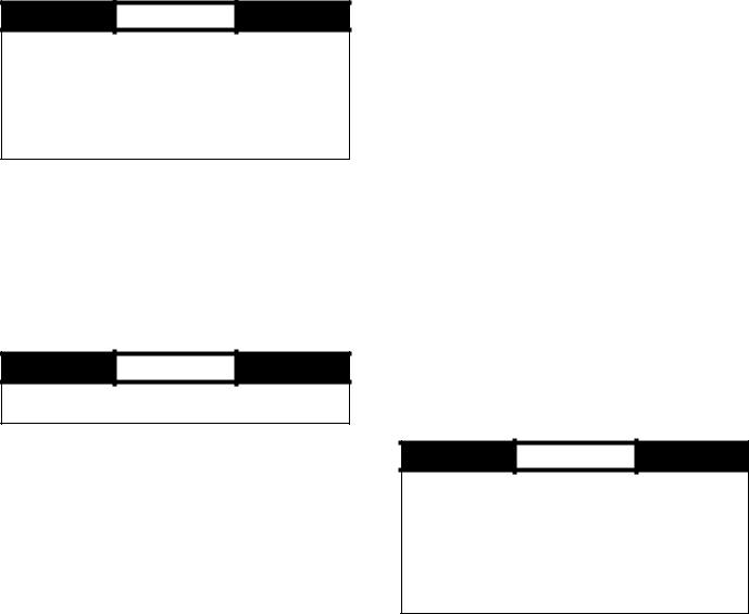
ROOF CURB — Assemble and install roof curb as described in instructions shipped with the accessory. Accessory roof curb and information required to field fabricate a roof curb is shown in Fig. 1-5. Install insulation, cant strips, roofing and counter flashing as required. For unit condensate drain to function properly, curb must be level or within tolerances shown in Fig. 1-5.
STEEL BEAMS — If roof curb is not used, support unit with steel beams along its entire length and then support steel as required. As a minimum, unit must be supported across its width at each lifting lug location.
Slab Mount — Provide a level concrete slab that extends beyond unit cabinet at least 6 inches. Make a slab 8 in. thick with 4 in. above grade. Use gravel apron in front of condenser coil air inlet to prevent grass and foliage from obstructing airflow. Ensure that slab is of sufficient height to allow for condensate trap of 4 in. on sizes 030-070 or 7 in. on sizes 075-105.
Curb Gasketing
SIZE 030-050 UNITS — After ductwork has been connected to the roof curb, attach adhesive-backed gasketing on all end rails, cross rails, and duct rails. Be sure all joints and corners of gasket are square and flush to prevent possible water leaks. Follow all applicable building codes.
SIZE 055-105 UNITS — After ductwork has been connected to the roof curb, apply gasket material (1/2-in. thick x 11/2-in. wide neoprene) where indicated.
Single-Thickness Gasketing (See Fig. 6-8 for Item Numbers) — Apply gasketing in the following places:
1.Along both side rails (1) — 2 places, full length
2.Along return air end rail (2) — 1 place
3.Around return air internal duct flange (3) — 1 or 2 places
4.Around supply air internal duct flanges (4) — 3 places
Double-Thickness Gasketing (See Fig. 6 and 8 and Detail A-A) — Locate a line 93/4-in. from the supply air end of the accessory curb. Apply a double-thickness of gasket material along with line per detail A-A.
NOTE: Do not apply gasket material along the outside edge of the curb (area “X”). This pan area of the curb extends out beneath the end of the unit’s air handler section; applying gasket here develops a potential water trap area on top of the curb.
Condenser Section Roof Curb (See Fig. 7) — Apply singlethickness gasket along both side rails (5).
Field-Fabricated Ductwork
 WARNING
For vertical supply and return units, tools or parts could drop into ductwork and cause an injury. Install a 90-degree turn in the supply and return ductwork between the unit and the conditioned space. If a 90-degree elbow cannot be installed, then a grille of sufficient strength and density should be installed to prevent objects from falling into the conditioned space. Failure to follow these instructions could result in personal injury or property damage due to falling objects.
The 48ZG,ZN,ZT,ZW,Z6,Z8 units are designed for vertical supply/return only. Field-fabricated ductwork must be attached to the roof curb, on to the support steel, prior to the final rigging and installation of the unit. Supply and return duct dimensions are shown in Fig. 1-3.
To attach ductwork to roof curb, insert duct approximately 10 to 11 in. up into roof curb. Connect ductwork to 14-gage roof curb material with sheet metal screws driven from inside the duct.
Secure all ducts to the building structure, using flexible duct connectors between roof curbs and ducts as required. Ducts passing through an unconditioned space must be insulated and covered with a vapor barrier. Outlet grilles must not lie directly below unit discharge. The return duct must have a 90-degree elbow before opening into the building space if the unit is equipped with power exhaust.
Design supply duct strong enough to handle expected static pressures.
Rigging — Do not drop unit; keep upright. Use spreader bars over unit to prevent sling or cable damage. Sheets of plywood placed along the condenser coils will provide additional protection. All lifting lugs MUST be used when lifting unit. Level by using unit frame as a reference. See Fig. 9-13 for information. Unit and accessory weights are shown in Tables 1A1E and 2. Weight distribution and center of gravity can be found in Fig. 14.
2
Table 1A — Physical Data (48ZG,ZN030-050)
BASE UNIT |
|
48ZG,ZN030 |
|
|
|
|
|
|
48ZG,ZN035 |
|
|||||
NOMINAL CAPACITY (tons) |
|
30 |
|
|
|
|
|
|
35 |
|
|||||
OPERATING WEIGHT (lb) |
|
Standard Chassis |
|
|
Extended Chassis |
|
|
Standard Chassis |
|
Extended Chassis |
|||||
Base Unit |
|
|
|
|
|
|
|
|
|
|
|
|
|
||
|
Low Heat |
|
5640 |
|
|
6140 |
|
|
|
5766 |
|
|
6266 |
||
|
High Heat |
|
5770 |
|
|
6270 |
|
|
|
5895 |
|
|
6395 |
||
With Economizer |
|
|
|
|
|
|
|
|
|
|
|
|
|
||
|
Low Heat |
|
5941 |
|
|
6441 |
|
|
|
6066 |
|
|
6566 |
||
|
High Heat |
|
6070 |
|
|
6570 |
|
|
|
6195 |
|
|
6695 |
||
COMPRESSORS |
|
|
|
|
|
|
Semi-Hermetic |
|
|
|
|||||
Quantity...Type |
|
2...06D |
|
|
|
|
|
|
1...06D, 1...06E |
||||||
Oil Charge (pints) |
|
8 |
|
|
|
|
|
|
8, 14 |
|
|||||
Capacity Steps (%) |
|
|
|
|
|
|
|
|
|
|
|
|
|
||
|
CV |
|
|
50,100 |
|
|
|
|
|
|
43,100 |
|
|||
|
VAV |
|
|
17,33,50,67,83,100 |
|
|
|
|
|
14,28,42,57,71,86,100 |
|||||
Number of Refrigerant Circuits |
|
2 |
|
|
|
|
|
|
2 |
|
|||||
REFRIGERANT |
|
|
|
|
|
|
R-22 |
|
|
|
|||||
Operating Charge (lb), Ckt 1/Ckt 2 |
|
|
|
|
|
|
|
|
|
|
|
|
|
||
|
Standard Evaporator Coil |
|
29.0/29.0 |
|
|
|
|
|
|
29.0/30.5 |
|
||||
|
|
|
|
|
|
|
|
|
|||||||
|
Standard Evaporator with HGBP |
|
31.0/29.0 |
|
|
|
|
|
|
31.0/30.5 |
|
||||
|
Alternate High-Capacity Evaporator Coil |
|
N/A |
|
|
|
|
|
|
N/A |
|
||||
|
Alternate High-Capacity Evaporator with HGBP |
|
N/A |
|
|
|
|
|
|
N/A |
|
||||
CONDENSER COILS |
|
|
|
|
3/8-in. Tube Diameter |
|
|
|
|||||||
Quantity |
|
2 |
|
|
|
|
|
|
2 |
|
|||||
Rows...Fins/in. |
|
|
|
|
|
|
|
|
|
|
|
|
|
||
|
Aluminum |
|
3...15.0 |
|
|
|
|
|
|
3...15.0 |
|
||||
|
Copper (Optional) |
|
3...13.7 |
|
|
|
|
|
|
3...13.7 |
|
||||
Total Face Area (sq ft) |
|
37.5 |
|
|
|
|
|
|
37.5 |
|
|||||
EVAPORATOR COILS |
|
|
|
|
|
|
|
|
|
|
|
|
|
||
Quantity |
|
|
|
|
|
|
1 |
|
|
|
|
||||
Total Face Area (sq ft) |
|
|
|
|
|
|
32.1 |
|
|
|
|
||||
Refrigerant Feed Device...No. per Circuit |
|
|
|
|
|
|
TXV...1 |
|
|
|
|||||
Standard Evaporator Coils |
|
1/2 in. Tube Dia |
|
|
|
|
1/2 in. Tube Dia |
|
|||||||
|
|
|
|
|
|
||||||||||
|
Rows...Fins/in. |
|
3...15.0 |
|
|
|
|
|
|
4...15.0 |
|
||||
|
Fin Type |
|
Double Wavy |
|
|
|
|
|
|
Double Wavy |
|
||||
|
Tube Type |
|
Cross Hatched |
|
|
|
|
Cross Hatched |
|
||||||
Alternate, High-Capacity Evaporator Coils |
|
N/A |
|
|
|
|
|
|
N/A |
|
|||||
|
Rows...Fins/in. |
|
N/A |
|
|
|
|
|
|
N/A |
|
||||
|
Fin Type |
|
N/A |
|
|
|
|
|
|
N/A |
|
||||
|
Tube Type |
|
N/A |
|
|
|
|
|
|
N/A |
|
||||
HEATING SECTION |
|
Low Heat |
|
|
High Heat |
|
|
Low Heat |
|
|
High Heat |
||||
Number of Heat Exchangers |
|
1 |
|
|
2 |
|
|
|
1 |
|
|
2 |
|||
Input (MBtuh) |
|
325 |
|
|
650 |
|
|
|
325 |
|
|
650 |
|||
Output (MBtuh) |
|
263 |
|
|
527 |
|
|
|
263 |
|
|
527 |
|||
Temperature Rise Range (F) |
|
10-40 |
|
|
25-55 |
|
|
|
10-40 |
|
|
25-55 |
|||
Efficiency (%) |
|
81 |
|
|
81 |
|
|
|
81 |
|
|
81 |
|||
Burner Orifice Diameter |
|
|
|
|
|
|
|
|
|
|
|
|
|
||
|
Quantity (in. ...drill no.) |
|
7 (.1285...30) |
|
|
14 (.1285...30) |
|
|
|
7 (.1258...30) |
|
14 (.1258...30) |
|||
Manifold Pressure (in. wg) |
|
3.3 |
|
|
3.3 |
|
|
|
3.3 |
|
|
3.3 |
|||
Line Pressure (in. wg) (min...max) |
|
5.0...13.0 |
|
|
5.0...13.0 |
|
|
|
5.0...13.0 |
|
|
5.0...13.0 |
|||
Firing Stages |
|
2 |
|
|
2 |
|
|
|
2 |
|
|
2 |
|||
Number of Gas Valves |
|
1 |
|
|
2 |
|
|
|
1 |
|
|
2 |
|||
CONDENSER FANS |
|
|
|
|
|
|
Propeller Type |
|
|
|
|||||
Quantity...Diameter (in.) |
|
2...30 |
|
|
|
|
|
|
2...30 |
|
|||||
Nominal Cfm |
|
18,600 |
|
|
|
|
|
|
18,600 |
|
|||||
Motor Hp...Rpm |
|
1.0...1140 |
|
|
|
|
|
|
1.0...1140 |
|
|||||
SUPPLY FAN |
|
|
|
|
Centrifugal 25 x 25 in. |
|
|
|
|||||||
Nominal Cfm |
|
10,500 |
|
|
|
|
|
|
10,500 |
|
|||||
Maximum Allowable Cfm |
|
15,000 |
|
|
|
|
|
|
15,000 |
|
|||||
Maximum Allowable Rpm |
|
900 |
|
|
|
|
|
|
900 |
|
|||||
Shaft Diameter at Pulley (in.) |
|
111/16 |
|
|
|
|
|
|
111/16 |
|
|||||
SUPPLY-FAN MOTOR AND DRIVE |
|
|
|
|
(Any motor available on any unit) |
|
|
|
|||||||
Motor Hp |
|
7.5 |
|
|
10 |
|
15 |
|
20 |
|
25 |
||||
Motor Frame Size |
|
213T |
|
215T |
|
|
|
254T |
|
256T |
284T |
||||
Efficiency at Full Load (%) |
|
|
|
|
|
|
|
|
|
|
|
|
|
||
|
High Efficiency |
|
88.5 |
|
|
89.5 |
|
91.0 |
|
91.0 |
|
91.7 |
|||
|
Premium Efficiency |
|
91.7 |
|
|
91.7 |
|
93.0 |
|
93.6 |
|
93.6 |
|||
Fan Pulley Pitch Diameter (in.) |
|
13.7 |
|
|
13.7 |
|
13.7 |
|
13.7 |
|
13.7 |
||||
Motor Pulley Pitch Diameter (in.) |
|
3.4 |
|
|
4.3 |
|
4.9 |
|
5.5 |
|
6.5 |
||||
Resulting Fan Speed (rpm) |
|
438 |
|
|
549 |
|
626 |
|
703 |
|
830 |
||||
Belts Quantity...Type |
|
2...BX60 |
|
2...5VX630 |
|
2...5VX630 |
|
2...5VX630 |
2...5VX650 |
||||||
Center Distance Range (in.) |
|
17.74-14.30 |
|
|
17.74-14.30 |
|
17.63-14.01 |
|
17.63-14.01 |
16.63-12.87 |
|||||
OPTIONAL POWER EXHAUST |
|
|
|
Centrifugal, 18 x 15 |
in. (Any motor available |
on any unit) |
|
||||||||
Quantity...Motor Hp |
|
2...3.0 |
|
|
2...5.0 |
|
|
|
2...7.5 |
|
|
2...10 |
|||
|
|
|
|
|
|
||||||||||
Motor Frame Size |
High Eff |
56HZ |
|
|
184T |
|
|
213T |
|
|
215T |
||||
Efficiency at Full Load (%) High/Premium |
Prem Eff |
182T |
|
|
184T |
|
|
213T |
|
|
215T |
||||
|
81.0/88.5 |
|
|
87.5/89.5 |
|
|
|
88.5/91.7 |
|
|
89.5/91.7 |
||||
Fan Pulley Pitch Diameter (in.) |
High Eff |
11 |
|
|
10.4 |
|
|
|
12 |
|
|
12 |
|||
|
|
|
Prem Eff |
11.0 |
|
|
10.4 |
|
|
|
12 |
|
|
12 |
|
Motor Pulley Pitch Diameter Range (in.) |
High Eff |
4.1-3.1 |
|
|
4.7-3.7 |
|
|
|
6.0-4.8 |
|
|
7.0-5.8 |
|||
Motor Pulley Pitch Diameter Factory Setup (in.) |
Prem Eff |
4.1-3.1 |
|
|
4.7-3.7 |
|
|
|
6.0-4.8 |
|
|
7.0-5.8 |
|||
|
4.1 |
|
|
4.2 |
|
|
|
5.4 |
|
|
6.4 |
||||
Blower Shaft Diameter at Pulley (in.) |
|
17/16 |
|
|
17/16 |
|
|
|
17/16 |
|
|
17/16 |
|||
Fan Rpm Range |
|
500-656 |
|
|
621-785 |
|
|
|
717-882 |
|
|
854-1000 |
|||
Factory Setup Fan Rpm |
|
656 |
|
|
703 |
|
|
|
800 |
|
|
927 |
|||
Maximum Allowable Rpm |
|
1000 |
|
|
1000 |
|
|
|
1000 |
|
|
1000 |
|||
Belts Quantity...No. |
High Eff |
1...BX71 |
|
|
1...BX71 |
|
|
1...BX77 |
|
|
1...BX79 |
||||
Center Distance Range (in.) |
Prem Eff |
1...BX71 |
|
|
1...BX71 |
|
|
1...BX77 |
|
|
1...BX79 |
||||
|
23.62-26.50 |
|
|
23.62-26.50 |
|
|
|
23.62-26.50 |
|
23.62-26.50 |
|||||
FILTERS |
|
|
|
|
|
|
|
|
|
|
|
|
|
|
|
Standard Efficiency Throwaway (Standard) |
|
8...20 x 25 x 2 |
|
|
|
|
8...20 x 25 x 2 |
|
|||||||
|
Quantity...Size (in.) |
|
8...20 x 20 x 2 |
|
|
|
|
8...20 x 20 x 2 |
|||||||
Medium Efficiency (30%) Pleated (Optional) |
|
8...20 x 25 x 2 |
|
|
|
|
8...20 x 25 x 2 |
|
|||||||
|
Quantity...Size (in.) |
|
8...20 x 20 x 2 |
|
|
|
|
8...20 x 20 x 2 |
|||||||
High Efficiency (90%) Bag Filters |
|
|
|
|
|
|
|
|
|
|
|
|
|
||
|
with High Velocity Prefilters (Optional) |
|
|
|
|
|
|
|
|
|
|
|
|
|
|
|
Quantity...Size (in.) |
|
6...20 x 24 x 22 |
|
|
|
|
6...20 x 24 x 22 |
|||||||
|
Bag Filter |
|
|
|
|
|
|||||||||
|
|
6...20 x 20 x 22 |
|
|
|
|
6...20 x 20 x 22 |
||||||||
|
|
|
|
|
|
|
|
||||||||
|
Prefilter |
|
12...16 x 20 x 2 |
|
|
|
|
12...16 x 20 x 2 |
|||||||
|
|
3...20 x 24 x 2 |
|
|
|
|
3...20 x 24 x 2 |
||||||||
|
|
|
|
|
|
|
|
||||||||
OUTSIDE AIR SCREENS |
|
|
|
|
|
|
|
|
|
|
|
|
|
||
Standard Hood (25%) Quantity...Size (in.) |
|
None |
|
|
|
|
|
|
None |
|
|||||
OPTIONAL ECONOMIZER FILTER |
|
5...20 x 20 x 2 |
Aluminum Frame, Permanent |
5...20 x 20 x 1 |
|
||||||||||
Quantity...Size (in.) |
|
|
|
|
|
|
|
|
|||||||
|
2...20 x 25 x 1 |
|
|
|
|
|
|
2...20 x 25 x 1 |
|
||||||
|
|
|
|
|
|
|
|
|
|
|
|||||
|
LEGEND |
|
|
|
*460-3-60 only. |
|
|
|
|
|
|
|
|||
CV |
— Constant Volume |
|
|
|
|
|
|
|
|
|
|
|
|
|
|
HGBP |
— Hot Gas Bypass |
|
|
|
|
|
|
|
|
|
|
|
|
|
|
MBtuh |
— |
Btuh in Thousands |
|
|
|
|
|
|
|
|
|
|
|
|
|
TXV |
— |
Thermostatic Expansion Valve |
|
|
|
|
|
|
|
|
|
|
|
|
|
VAV |
— |
Variable Air Volume |
|
|
|
|
|
|
|
|
|
|
|
|
|
3
Table 1A — Physical Data (48ZG,ZN030-050) (cont)
BASE UNIT |
|
|
|
48ZG,ZN040 |
|
|
|
|
|
|
|
48ZG,ZN050 |
|
|||||
NOMINAL CAPACITY (tons) |
|
|
|
40 |
|
|
|
|
|
|
|
50 |
|
|
||||
OPERATING WEIGHT (lb) |
|
Standard Chassis |
|
Extended Chassis |
|
|
|
Standard Chassis |
|
|
Extended Chassis |
|||||||
Base Unit |
|
|
|
|
|
|
|
|
|
|
|
|
|
|
|
|
||
|
Low Heat |
|
6540 |
|
|
|
7040 |
|
|
|
6581 |
|
|
|
7081 |
|||
|
High Heat |
|
6670 |
|
|
|
7170 |
|
|
|
6710 |
|
|
|
7210 |
|||
With Economizer |
|
|
|
|
|
|
|
|
|
|
|
|
|
|
|
|
||
|
Low Heat |
|
6841 |
|
|
|
7341 |
|
|
|
6881 |
|
|
|
7381 |
|||
|
High Heat |
|
6970 |
|
|
|
7470 |
|
|
|
7010 |
|
|
|
7510 |
|||
COMPRESSORS |
|
|
|
|
|
|
Semi-Hermetic |
|
|
|
|
|||||||
Quantity...Type |
|
|
|
2...06E |
|
|
|
|
|
|
|
2...06E |
|
|||||
Oil Charge (pints) |
|
|
|
14 |
|
|
|
|
|
|
|
19, 14 |
|
|
||||
Capacity Steps (%) |
|
|
|
|
|
|
|
|
|
|
|
|
|
|
|
|
||
|
CV |
|
|
|
|
50,100 |
|
|
|
|
|
|
|
57,100 |
|
|
||
|
VAV |
|
|
|
|
25,50,75,100 |
|
|
|
|
|
|
|
18,37,56,63,81,100 |
||||
Number of Refrigerant Circuits |
|
|
|
2 |
|
|
|
|
|
|
|
2 |
|
|
||||
REFRIGERANT |
|
|
|
|
|
|
|
R-22 |
|
|
|
|
||||||
Operating Charge (lb), Ckt 1/Ckt 2 |
|
|
|
|
|
|
|
|
|
|
|
|
|
|
|
|
||
|
Standard Evaporator Coil |
|
|
|
40.0/40.0 |
|
|
|
|
|
|
|
41.5/39.0 |
|
|
|||
|
|
|
|
|
|
|
|
|
|
|
|
|||||||
|
Standard Evaporator with HGBP |
|
|
|
42.0/40.0 |
|
|
|
|
|
|
|
43.5/39.0 |
|
|
|||
|
Alternate High-Capacity Evaporator Coil |
|
|
|
50.0/51.0 |
|
|
|
|
|
|
|
49.0/49.0 |
|
|
|||
|
Alternate High-Capacity Evaporator with HGBP |
|
|
|
52.0/51.0 |
|
|
|
|
|
|
|
51.0/49.0 |
|
|
|||
CONDENSER COILS |
|
|
|
|
|
|
3/8-in. Tube Diameter |
|
|
|
|
|||||||
Quantity |
|
|
|
2 |
|
|
|
|
|
|
|
2 |
|
|
||||
Rows...Fins/in. |
|
|
|
|
|
|
|
|
|
|
|
|
|
|
|
|
||
|
Aluminum |
|
|
|
3...15.0 |
|
|
|
|
|
|
|
3...15.0 |
|
|
|||
|
Copper (Optional) |
|
|
|
3...13.7 |
|
|
|
|
|
|
|
3...13.7 |
|
|
|||
Total Face Area (sq ft) |
|
|
|
50.0 |
|
|
|
|
|
|
|
50.0 |
|
|
||||
EVAPORATOR COILS |
|
|
|
|
|
|
|
|
|
|
|
|
|
|
|
|
||
Quantity |
|
|
|
|
|
|
|
2 |
|
|
|
|
|
|||||
Total Face Area (sq ft) |
|
|
|
|
|
|
|
45.5 |
|
|
|
|
|
|||||
Refrigerant Feed Device...No. per Circuit |
|
|
|
|
|
|
|
TXV...2 |
|
|
|
|
||||||
Standard Evaporator Coils |
|
|
|
1/2 in. Tube Dia |
|
|
|
|
|
|
|
1/2 in. Tube Dia |
||||||
|
|
|
|
|
|
|
|
|
|
|||||||||
|
Rows...Fins/in. |
|
|
|
3...15.0 |
|
|
|
|
|
|
|
4...15.0 |
|
|
|||
|
Fin Type |
|
|
|
Double Wavy |
|
|
|
|
|
|
|
Double Wavy |
|
||||
|
Tube Type |
|
|
|
Cross Hatched |
|
|
|
|
|
|
|
Cross Hatched |
|||||
Alternate, High-Capacity Evaporator Coils |
|
|
|
1/2 in. Tube Dia |
|
|
|
|
|
|
|
1/2 in. Tube Dia |
||||||
|
Rows...Fins/in. |
|
|
|
6...16.0 |
|
|
|
|
|
|
|
6...16.0 |
|
|
|||
|
Fin Type |
|
|
|
Double Wavy |
|
|
|
|
|
|
|
Double Wavy |
|
||||
|
Tube Type |
|
|
|
Cross Hatched |
|
|
|
|
|
|
|
Cross Hatched |
|||||
HEATING SECTION |
|
Low Heat |
|
|
|
High Heat |
|
|
|
Low Heat |
|
|
|
High Heat |
||||
Number of Heat Exchangers |
|
1 |
|
|
|
2 |
|
|
|
1 |
|
|
|
|
2 |
|||
Input (MBtuh) |
|
325 |
|
|
|
650 |
|
|
|
325 |
|
|
|
|
650 |
|||
Output (MBtuh) |
|
263 |
|
|
|
527 |
|
|
|
263 |
|
|
|
|
527 |
|||
Temperature Rise Range (F) |
|
10-40 |
|
|
|
25-55 |
|
|
|
10-40 |
|
|
|
25-55 |
||||
Efficiency (%) |
|
81 |
|
|
|
81 |
|
|
|
81 |
|
|
|
|
81 |
|||
Burner Orifice Diameter |
|
|
|
|
|
|
|
|
|
|
|
|
|
|
|
|
||
|
Quantity (in. ...drill no.) |
|
7 (.1285...30) |
|
|
|
14 (.1285...30) |
|
|
|
7 (.1285...30) |
|
|
14 (.1285...30) |
||||
Manifold Pressure (in. wg) |
|
3.3 |
|
|
|
3.3 |
|
|
|
3.3 |
|
|
|
|
3.3 |
|||
Line Pressure (in. wg) (min...max) |
|
5.0...13.0 |
|
|
|
5.0...13.0 |
|
|
|
5.0...13.0 |
|
|
|
5.0...13.0 |
||||
Firing Stages |
|
2 |
|
|
|
2 |
|
|
|
2 |
|
|
|
|
2 |
|||
Number of Gas Valves |
|
1 |
|
|
|
2 |
|
|
|
1 |
|
|
|
|
2 |
|||
CONDENSER FANS |
|
|
|
|
|
|
Propeller Type |
|
|
|
|
|||||||
Quantity...Diameter (in.) |
|
|
|
3...30 |
|
|
|
|
|
|
|
3...30 |
|
|
||||
Nominal Cfm |
|
|
|
26,000 |
|
|
|
|
|
|
|
26,000 |
|
|
||||
Motor Hp...Rpm |
|
|
|
1.0...1140 |
|
|
|
|
|
|
|
1.0...1140 |
|
|||||
SUPPLY FAN |
|
|
|
|
|
|
Centrifugal 25 x 25 in. |
|
|
|
|
|||||||
Nominal Cfm |
|
|
|
14,000 |
|
|
|
|
|
|
|
14,000 |
|
|
||||
Maximum Allowable Cfm |
|
|
|
20,000 |
|
|
|
|
|
|
|
20,000 |
|
|
||||
Maximum Allowable Rpm |
|
|
|
900 |
|
|
|
|
|
|
|
900 |
|
|
||||
Shaft Diameter at Pulley (in.) |
|
|
|
111/16 |
|
|
|
|
|
|
|
111/16 |
|
|
||||
SUPPLY-FAN MOTOR AND DRIVE |
|
|
|
|
|
|
(Any motor available on any unit) |
|
|
|
|
|||||||
Motor Hp |
|
7.5 |
|
10 |
|
15 |
|
20 |
|
25 |
|
|
30* |
|||||
Motor Frame Size |
|
213T |
|
215T |
|
254T |
|
|
|
256T |
|
284T |
|
286T |
||||
Efficiency at Full Load (%) |
|
|
|
|
|
|
|
|
|
|
|
|
|
|
|
|
||
|
High Efficiency |
|
88.5 |
|
89.5 |
|
91.0 |
|
91.0 |
|
91.7 |
|
|
92.4 |
||||
|
Premium Efficiency |
|
91.7 |
|
91.7 |
|
93.0 |
|
93.6 |
|
93.6 |
|
|
93.6 |
||||
Fan Pulley Pitch Diameter (in.) |
|
13.7 |
|
13.7 |
|
13.7 |
|
13.7 |
|
13.7 |
|
|
12.5 |
|||||
Motor Pulley Pitch Diameter (in.) |
|
3.4 |
|
4.3 |
|
4.9 |
|
5.5 |
|
6.5 |
|
|
6.5 |
|||||
Resulting Fan Speed (rpm) |
|
438 |
|
549 |
|
626 |
|
703 |
|
830 |
|
|
910 |
|||||
Belts Quantity...Type |
|
2...BX60 |
|
2...5VX630 |
|
2...5VX630 |
|
|
|
2...5VX630 |
|
2...5VX650 |
|
3...5VX630 |
||||
Center Distance Range (in.) |
|
17.74-14.30 |
|
17.74-14.30 |
|
17.63-14.01 |
|
17.63-14.01 |
|
16.63-12.87 |
|
16.63-12.87 |
||||||
OPTIONAL POWER EXHAUST |
|
|
|
|
Centrifugal, 18 x 15 in. (Any motor available on |
any unit) |
|
|||||||||||
Quantity...Motor Hp |
|
2...3.0 |
|
|
|
2...5.0 |
|
|
|
2...7.5 |
|
|
|
2...10 |
||||
|
|
|
|
|
|
|
||||||||||||
Motor Frame Size |
High Eff |
56HZ |
|
|
|
184T |
|
|
|
213T |
|
|
|
215T |
||||
Efficiency at Full Load (%) High/Premium |
Prem Eff |
182T |
|
|
|
184T |
|
|
|
213T |
|
|
|
215T |
||||
|
81.0/88.5 |
|
|
|
87.5/89.5 |
|
|
|
88.5/91.7 |
|
|
|
89.5/91.7 |
|||||
Fan Pulley Pitch Diameter (in.) |
High Eff |
11 |
|
|
|
10.4 |
|
|
|
12 |
|
|
|
|
12 |
|||
|
|
|
Prem Eff |
11.0 |
|
|
|
10.4 |
|
|
|
12 |
|
|
|
|
12 |
|
Motor Pulley Pitch Diameter Range (in.) |
High Eff |
4.1-3.1 |
|
|
|
4.7-3.7 |
|
|
|
6.0-4.8 |
|
|
|
7.0-5.8 |
||||
Motor Pulley Pitch Diameter Factory Setup (in.) |
Prem Eff |
4.1-3.1 |
|
|
|
4.7-3.7 |
|
|
|
6.0-4.8 |
|
|
|
7.0-5.8 |
||||
|
4.1 |
|
|
|
4.2 |
|
|
|
5.4 |
|
|
|
|
6.4 |
||||
Blower Shaft Diameter at Pulley (in.) |
|
17/16 |
|
|
|
17/16 |
|
|
|
17/16 |
|
|
|
17/16 |
||||
Fan Rpm Range |
|
500-656 |
|
|
|
621-785 |
|
|
|
717-882 |
|
|
|
854-1000 |
||||
Factory Setup Fan Rpm |
|
656 |
|
|
|
703 |
|
|
|
800 |
|
|
|
|
927 |
|||
Maximum Allowable Rpm |
|
1000 |
|
|
|
1000 |
|
|
|
1000 |
|
|
|
1000 |
||||
Belts Quantity...No. |
High Eff |
1...BX71 |
|
|
|
1...BX71 |
|
|
|
1...BX77 |
|
|
|
1...BX79 |
||||
Center Distance Range (in.) |
Prem Eff |
1...BX71 |
|
|
|
1...BX71 |
|
|
|
1...BX77 |
|
|
|
1...BX79 |
||||
|
23.62-26.50 |
|
|
|
23.62-26.50 |
|
|
|
23.62-26.50 |
|
|
|
23.62-26.50 |
|||||
FILTERS |
|
|
|
|
|
|
|
|
|
|
|
|
|
|
|
|
|
|
Standard Efficiency Throwaway (Standard) |
|
|
|
8...20 x 25 x 2 |
|
|
|
|
|
|
|
8...20 x 25 x 2 |
|
|||||
|
Quantity...Size (in.) |
|
|
|
8...20 x 20 x 2 |
|
|
|
|
|
|
|
8...20 x 20 x 2 |
|||||
Medium Efficiency (30%) Pleated (Optional) |
|
|
|
8...20 x 25 x 2 |
|
|
|
|
|
|
|
8...20 x 25 x 2 |
||||||
|
Quantity...Size (in.) |
|
|
|
8...20 x 20 x 2 |
|
|
|
|
|
|
|
8...20 x 20 x 2 |
|||||
High Efficiency (90%) Bag Filters |
|
|
|
|
|
|
|
|
|
|
|
|
|
|
|
|
||
|
with High Velocity Prefilters (Optional) |
|
|
|
|
|
|
|
|
|
|
|
|
|
|
|
|
|
|
Quantity...Size (in.) |
|
|
6...20 x 24 x 22 |
|
|
|
|
|
|
|
6...20 x 24 x 22 |
||||||
|
Bag Filter |
|
|
|
|
|
|
|
|
|
||||||||
|
|
|
6...20 x 20 x 22 |
|
|
|
|
|
|
|
6...20 x 20 x 22 |
|||||||
|
|
|
|
|
|
|
|
|
|
|
|
|||||||
|
Prefilter |
|
|
12...16 x 20 x 2 |
|
|
|
|
|
|
|
12...16 x 20 x 2 |
||||||
|
|
|
|
3...20 x 24 x 2 |
|
|
|
|
|
|
|
3...20 x 24 x 2 |
||||||
|
|
|
|
|
|
|
|
|
|
|
|
|
||||||
OUTSIDE AIR SCREENS |
|
|
|
|
|
|
|
|
|
|
|
|
|
|
|
|
||
Standard Hood (25%) Quantity...Size (in.) |
|
|
|
None |
|
|
|
|
|
|
|
None |
|
|||||
OPTIONAL ECONOMIZER FILTER |
|
|
|
5...20 x 20 x 2 |
|
Aluminum Frame, Permanent |
5...20 x 20 x 1 |
|
||||||||||
Quantity...Size (in.) |
|
|
|
|
|
|
|
|
|
|
|
|||||||
|
|
|
2...20 x 25 x 1 |
|
|
|
|
|
|
|
2...20 x 25 x 1 |
|
||||||
|
|
|
|
|
|
|
|
|
|
|
|
|
|
|||||
|
LEGEND |
|
|
|
|
|
|
|
|
|
|
|
|
|
|
|
|
|
CV |
— Constant Volume |
|
|
|
|
|
|
|
|
|
|
|
|
|
|
|
|
|
HGBP |
— Hot Gas Bypass |
|
|
|
|
|
|
|
|
|
|
|
|
|
|
|
|
|
MBtuh |
— |
Btuh in Thousands |
|
|
|
|
|
|
|
|
|
|
|
|
|
|
|
|
TXV |
— |
Thermostatic Expansion Valve |
|
|
|
|
|
|
|
|
|
|
|
|
|
|
|
|
VAV |
— |
Variable Air Volume |
|
|
|
|
|
|
|
|
|
|
|
|
|
|
|
|
*460-3-60 only.
4
Table 1B — Physical Data (48ZG,ZN055-070)
BASE UNIT |
48ZG,ZN055 |
|
48ZG,ZN060 |
|
|
48ZG,ZN070 |
|||||||||
NOMINAL CAPACITY (tons) |
|
55 |
|
|
60 |
|
|
|
70 |
||||||
OPERATING WEIGHT (lb) |
Standard Chassis |
|
Extended Chassis |
|
Standard Chassis |
|
|
Extended Chassis |
|
|
Standard Chassis |
||||
|
Base Unit |
|
|
|
|
|
|
|
|
|
|
|
|
|
|
|
Low Heat |
8700 |
|
9248 |
|
9000 |
|
|
9,548 |
|
|
|
9,420 |
||
|
High Heat |
8820 |
|
9368 |
|
9120 |
|
|
9,668 |
|
|
|
9,550 |
||
|
With Economizer |
|
|
|
|
|
|
|
|
|
|
|
|
|
|
|
Low Heat |
9230 |
|
9730 |
|
9530 |
|
|
10,030 |
|
|
|
9,950 |
||
|
High Heat |
9350 |
|
9850 |
|
9650 |
|
|
10,450 |
|
|
10,080 |
|||
COMPRESSORS |
|
|
|
|
Semi-Hermetic |
|
|
|
|
||||||
|
Quantity...Type |
2...06E |
|
2...06E |
|
|
2...06E |
||||||||
|
|
|
|||||||||||||
|
Oil Charge (Pints) |
19, 14 |
|
|
19 |
|
|
|
19 |
||||||
|
Capacity Steps (%) |
|
|
|
|
|
|
|
|
|
|
|
|
|
|
|
CV |
60,100 |
|
50,100 |
|
|
45,100 |
||||||||
|
VAV |
20,40,60,80,100 |
|
17,33,50,67,83,100 |
|
|
14,29,43,51,66,71,85,100 |
||||||||
|
Number of Refrigerant Circuits |
|
2 |
|
|
2 |
|
|
|
2 |
|||||
REFRIGERANT |
|
|
|
|
R-22 |
|
|
|
|
||||||
|
Operating Charge (lb), Ckt 1/Ckt 2 |
|
|
|
|
|
|
|
|
|
|
|
|
|
|
|
Standard Evaporator Coil |
59.0/44.5 |
|
61.0/61.0 |
|
|
70.5/64.5 |
||||||||
|
|
|
|||||||||||||
|
Standard Evaporator with HGBP |
62.0/44.5 |
|
64.0/61.0 |
|
|
73.5/64.5 |
||||||||
|
Alternate High-Capacity Evaporator Coil |
72.0/58.0 |
|
69.5/69.5 |
|
|
82.5/74.5 |
||||||||
|
Alternate High-Capacity Evaporator |
75.0/58.0 |
|
72.5/69.5 |
|
|
85.5/74.5 |
||||||||
|
with HGBP |
|
|
|
|||||||||||
|
|
|
|
|
|
|
|
|
|
|
|
|
|
|
|
CONDENSER COILS |
|
|
|
|
3/8-in. Tube Diameter |
|
|
|
|
||||||
|
Quantity |
|
4 |
|
|
4 |
|
|
|
4 |
|||||
|
Rows...Fins/in. |
|
|
|
|
|
|
|
|
|
|
|
|
|
|
|
Aluminum |
2...17.0, 3...17.0 |
|
3...17.0 |
|
|
3...17.0 |
||||||||
|
Copper (Optional) |
2...15.7, 3...15.7 |
|
3...15.7 |
|
|
3...15.7 |
||||||||
|
Total Face Area (sq ft) |
|
72.4 |
|
|
72.4 |
|
|
108.4 |
||||||
EVAPORATOR COILS |
|
|
|
|
|
|
|
|
|
|
|
|
|
|
|
|
Quantity |
|
|
|
2 |
|
|
|
|
|
|
|
|
|
|
|
Total Face Area (sq ft) |
|
|
|
61.5 |
|
|
|
|
|
|
|
|
||
|
Refrigerant Feed Device...No. per Circuit |
|
|
|
|
TXV...2 |
|
|
|
|
|||||
|
Standard Evaporator Coils |
|
|
|
|
1/2 in. Tube Dia |
|
|
|
|
|||||
|
Rows...Fins/in. |
3...17.0 |
|
4...17.0 |
|
|
4...17.0 |
||||||||
|
Fin Type |
Double Wavy |
|
Double Wavy |
|
|
Double Wavy |
||||||||
|
Tube Type |
Smooth |
|
Smooth |
|
|
Smooth |
||||||||
|
Alternate, High-Capacity Evaporator Coils |
|
|
|
|
1/2 in. Tube Dia |
|
|
|
|
|
|
|||
|
Rows...Fins/in. |
|
6...16 |
|
|
6...16 |
|
|
6...16 |
||||||
|
|
|
|
|
|||||||||||
|
Fin Type |
Double Wavy |
|
Double Wavy |
|
|
Double Wavy |
||||||||
|
Tube Type |
Cross Hatched |
|
Cross Hatched |
|
|
Cross Hatched |
||||||||
HEATING SECTION |
Low Heat |
|
High Heat |
|
Low Heat |
|
|
High Heat |
|
|
Low Heat |
|
|
High Heat |
|
|
Number of Heat Exchangers |
2 |
|
3 |
|
2 |
|
|
3 |
|
|
2 |
|
|
3 |
|
Input (MBtuh) |
650 |
|
975 |
|
650 |
|
|
975 |
|
|
650 |
|
|
975 |
|
Output (MBtuh) |
527 |
|
790 |
|
527 |
|
|
790 |
|
|
527 |
|
|
790 |
|
Temperature Rise Range (F) |
10-40 |
|
20-50 |
|
10-40 |
|
|
20-50 |
|
|
10-40 |
|
|
20-50 |
|
Efficiency (%) |
81 |
|
81 |
|
81 |
|
|
81 |
|
|
81 |
|
|
81 |
|
Burner Orifice Diameter |
|
|
|
|
|
|
|
|
|
|
|
|
|
|
|
Quantity (in. ...drill no.) |
14 (.1285...30) |
|
21 (.1285...30) |
|
14 (.1285...30) |
|
|
21 (.1285...30) |
|
|
14 (.1285...30) |
|
|
21 (.1285...30) |
|
Manifold Pressure (in. wg) |
3.3 |
|
3.3 |
|
3.3 |
|
|
3.3 |
|
|
3.3 |
|
|
3.3 |
|
Line Pressure (in. wg) (min...max) |
5.0...13.0 |
|
5.0...13.0 |
|
5.0...13.0 |
|
|
5.0...13.0 |
|
|
5.0...13.0 |
|
|
5.0...13.0 |
|
Firing Stages |
2 |
|
2 |
|
2 |
|
|
2 |
|
|
2 |
|
|
2 |
|
Number of Gas Valves |
2 |
|
3 |
|
2 |
|
|
3 |
|
|
2 |
|
|
3 |
CONDENSER FANS |
|
|
|
|
Propeller Type |
|
|
|
|
||||||
|
Quantity...Diameter (in.) |
|
4...30 |
|
|
4...30 |
|
|
5...30 |
||||||
|
Nominal Cfm |
40,000 |
|
40,000 |
|
|
50,000 |
||||||||
|
Motor Hp...Rpm |
1.0...1140 |
|
1.0...1140 |
|
|
1.0...1140 |
||||||||
SUPPLY FAN |
|
|
|
|
Centrifugal 25 x 25 in. |
|
|
|
|
||||||
|
Nominal Cfm |
17,500 |
|
21,000 |
|
|
24,500 |
||||||||
|
|
|
|||||||||||||
|
Maximum Allowable Cfm |
25,000 |
|
30,000 |
|
|
30,000 |
||||||||
|
Maximum Allowable Rpm |
|
800 |
|
|
800 |
|
|
|
800 |
|||||
|
Shaft Diameter at Pulley (in.) |
|
111/16 |
|
|
111/16 |
|
|
111/16 |
||||||
SUPPLY-FAN MOTOR AND DRIVE |
|
|
|
|
(Any motor available on any unit) |
|
|
|
|
||||||
|
Motor Hp |
|
15 |
|
20 |
|
|
25 |
|
|
30 |
|
|
40 |
|
|
|
|
|
|
|
||||||||||
|
Motor Frame Size |
|
254T |
|
256T |
|
|
284T |
|
|
286T |
|
|
S324T |
|
|
Efficiency at Full Load (%) |
|
|
|
|
|
|
|
|
|
|
|
|
|
|
|
High Efficiency |
|
91.0 |
|
91.0 |
|
|
91.7 |
|
|
92.4 |
|
|
93.0 |
|
|
Premium Efficiency |
|
93.0 |
|
93.6 |
|
|
93.6 |
|
|
93.6 |
|
|
94.5 |
|
|
Fan Pulley Pitch Diameter (in.) |
|
13.7 |
|
13.7 |
|
|
13.7 |
|
|
15.5 |
|
|
16.1 |
|
|
Motor Pulley Pitch Diameter (in.) |
|
4.5 |
|
5.1 |
|
|
5.5 |
|
|
5.9 |
|
|
6.7 |
|
|
Resulting Fan Speed (rpm) |
|
575 |
|
651 |
|
|
703 |
|
|
711 |
|
|
740 |
|
|
Belts Quantity...Type |
2...5VX1230 |
|
2...5VX1230 |
|
|
2...5VX1230 |
|
|
2...5VX1230 |
|
|
3...5VX1250 |
||
|
Center Distance Range (in.) |
48.25-44.00 |
|
48.25-44.00 |
|
|
48.50-44.25 |
|
|
48.50-44.25 |
|
|
48.25-44.00 |
||
OPTIONAL POWER EXHAUST |
|
|
Centrifugal, 15 x 15 in. (Any motor available on any unit) |
|
|
|
|
||||||||
|
Quantity...Motor Hp |
|
2...5 |
|
2...7.5 |
|
|
2...10 |
|||||||
|
|
|
|
||||||||||||
|
Motor Frame Size |
|
184T |
|
|
213T |
|
|
215T |
||||||
|
Efficiency at Full Load (%) High/Premium |
87.5/89.5 |
|
88.5/91.7 |
|
|
89.5/91.7 |
||||||||
|
Resulting Fan Rpm |
|
740 |
|
|
820 |
|
|
|
920 |
|||||
|
Maximum Allowable Rpm |
|
1000 |
|
|
1000 |
|
|
1000 |
||||||
FILTERS |
|
|
|
|
|
|
|
|
|
|
|
|
|
|
|
|
Standard Efficiency Throwaway (Standard) |
12...20 x 25 x 2 |
|
12...20 x 25 x 2 |
|
|
12...20 x 25 x 2 |
||||||||
|
Quantity...Size (in.) |
12...20 x 20 x 2 |
|
12...20 x 20 x 2 |
|
|
12...20 x 20 x 2 |
||||||||
|
Medium Efficiency (30%) Pleated (Optional) |
12...20 x 25 x 2 |
|
12...20 x 25 x 2 |
|
|
12...20 x 25 x 2 |
||||||||
|
Quantity...Size (in.) |
12...20 x 20 x 2 |
|
12...20 x 20 x 2 |
|
|
12...20 x 20 x 2 |
||||||||
|
High Efficiency (90%) Bag Filters |
|
|
|
|
|
|
|
|
|
|
|
|
|
|
|
with High Velocity Prefilters (Optional) |
|
|
|
|
|
|
|
|
|
|
|
|
|
|
|
Quantity...Size (in.) |
6...24 x 24 x 22 |
|
6...24 x 24 x 22 |
|
|
6...24 x 24 x 22 |
||||||||
|
Bag Filter |
|
|
|
|||||||||||
|
6...24 x 20 x 22 |
|
6...24 x 20 x 22 |
|
|
6...24 x 20 x 22 |
|||||||||
|
|
|
|
|
|||||||||||
|
Prefilter |
6...24 x 24 x 2 |
|
6...24 x 24 x 2 |
|
|
6...24 x 24 x 2 |
||||||||
|
6...20 x 24 x 2 |
|
6...20 x 24 x 2 |
|
|
6...20 x 24 x 2 |
|||||||||
|
|
|
|
|
|||||||||||
OUTSIDE AIR SCREENS |
4...25 x 16 x 1 |
|
4...25 x 16 x 1 |
|
|
4...25 x 16 x 1 |
|||||||||
|
Standard Hood (25%) Quantity...Size (in.) |
|
|
|
|||||||||||
|
2...20 x 16 x 1 |
|
2...20 x 16 x 1 |
|
|
2...20 x 16 x 1 |
|||||||||
|
|
|
|
|
|||||||||||
OPTIONAL ECONOMIZER FILTER |
|
|
|
|
Aluminum Frame, Permanent |
|
|
|
|
||||||
|
Quantity...Size (in.) |
12...16 x 25 x 1 |
|
12...16 x 25 x 1 |
|
|
12...16 x 25 x 1 |
||||||||
|
|
|
|||||||||||||
|
2...16 x 20 x 1 |
|
2...16 x 20 x 1 |
|
|
2...16 x 20 x 1 |
|||||||||
|
|
|
|
|
|||||||||||
|
LEGEND |
|
|
|
|
|
|
|
|
|
|
|
|
|
|
CV |
— Constant Volume |
|
|
|
|
|
|
|
|
|
|
|
|
|
|
HGBP — Hot Gas Bypass |
|
|
|
|
|
|
|
|
|
|
|
|
|
|
|
MBtuh — Btuh in Thousands |
|
|
|
|
|
|
|
|
|
|
|
|
|
|
|
TXV |
— Thermostatic Expansion Valve |
|
|
|
|
|
|
|
|
|
|
|
|
|
|
VAV |
— Variable Air Volume |
|
|
|
|
|
|
|
|
|
|
|
|
|
|
5
Table 1C — Physical Data (48ZG,ZN075-105)
BASE UNIT |
48ZG,ZN075 |
|
|
|
|
48ZG,ZN090 |
|
|
|
48ZG,ZN105 |
|||||||||||||||
NOMINAL CAPACITY (tons) |
75 |
|
|
|
|
|
90 |
|
|
|
|
|
|
|
|
105 |
|||||||||
OPERATING WEIGHT (lb) |
|
|
|
|
|
|
|
|
|
|
|
|
|
|
|
|
|
|
|
|
|
|
|
|
|
Base Unit without Economizer |
|
|
|
|
|
|
|
|
|
|
|
|
|
|
|
|
|
|
|
|
|
|
|
|
|
Low Heat/High Heat |
10,270/10,445 |
|
|
|
|
|
10,480/10,655 |
|
|
|
11,210/11,385 |
||||||||||||||
With Economizer |
|
|
|
|
|
|
|
|
|
|
|
|
|
|
|
|
|
|
|
|
|
|
|
|
|
Low Heat/High Heat |
10,800/10,975 |
|
|
|
|
|
11,010/11,185 |
|
|
|
11,740/11,915 |
||||||||||||||
COMPRESSOR |
|
|
|
|
|
|
|
|
|
Semi-Hermetic |
|
|
|
|
|
|
|||||||||
Number |
|
2 |
|
|
|
|
|
|
|
2 |
|
|
|
|
|
|
|
|
4 |
||||||
|
|
|
|
|
|
|
|
|
|
|
|||||||||||||||
Circuit (No. Cyl) |
A (6) |
|
B (6) |
|
|
|
|
A (6) |
|
|
|
|
B (6) |
|
|
A1 (6), A2 (4) |
|
|
B1 (6), B2 (4) |
||||||
|
|
|
|||||||||||||||||||||||
Model 06E |
-275 |
|
-299 |
|
|
|
|
-299 |
|
|
|
-299 |
|
|
|
-275, -250 |
|
|
|
-275, -250 |
|||||
Oil Charge (pints) |
19 |
|
19 |
|
|
|
|
|
19 |
|
|
|
19 |
|
|
|
19, 14 |
|
|
|
19, 14 |
||||
Capacity Steps (%) |
|
|
|
|
|
|
|
|
|
|
|
|
|
|
|
|
|
|
|
|
|
|
|
|
|
CV |
|
43,100 |
|
|
|
|
|
50,100 |
|
|
|
|
|
|
|
50,100 |
|||||||||
VAV |
|
14,29,43,51,66,86,100 |
|
|
|
|
17,33,50,67,83,100 |
|
|
|
20,30,40,50,60,60,70,80,80,90,100 |
||||||||||||||
Number of Refrigerant Circuits |
|
2 |
|
|
|
|
|
|
|
2 |
|
|
|
|
|
|
|
|
2 |
||||||
REFRIGERANT |
|
|
|
|
|
|
|
|
|
|
|
|
R-22 |
|
|
|
|
|
|
||||||
Operating Charge (lb), Ckt 1/Ckt 2 |
|
|
|
|
|
|
|
|
|
|
|
|
|
|
|
|
|
|
|
|
|
|
|
|
|
Standard Evaporator Coil |
70.5/64.5 |
|
|
|
|
|
64.0/64.0 |
|
|
|
|
|
68.0/68.0 |
||||||||||||
|
|
|
|
||||||||||||||||||||||
Standard Evaporator with HGBP |
73.5/64.5 |
|
|
|
|
|
67.0/64.0 |
|
|
|
|
|
71.0/68.0 |
||||||||||||
Alternate High-Capacity Evaporator Coil |
83.0/75.0 |
|
|
|
|
|
76.0/76.0 |
|
|
|
|
|
79.5/79.5 |
||||||||||||
Alternate High-Capacity Evaporator with HGBP |
86.0/75.0 |
|
|
|
|
|
79.0/76.0 |
|
|
|
|
|
82.5/79.5 |
||||||||||||
CONDENSER COILS |
|
|
|
|
|
|
|
|
3/8-in. Tube Diameter |
|
|
|
|
|
|
||||||||||
Quantity |
|
4 |
|
|
|
|
|
|
|
4 |
|
|
|
|
|
|
|
|
4 |
||||||
|
|
|
|
|
|
|
|
|
|
|
|||||||||||||||
Rows...Fins/in. |
|
|
|
|
|
|
|
|
|
|
|
|
|
|
|
|
|
|
|
|
|
|
|
|
|
Aluminum |
3...17.0 |
|
|
|
|
|
3...17.0 |
|
|
|
|
|
|
|
3...17.0 |
||||||||||
Copper (Optional) |
3...15.7 |
|
|
|
|
|
3...15.7 |
|
|
|
|
|
|
|
3...15.7 |
||||||||||
Fin Type |
Double Wavy |
|
|
|
|
Lanced, Sine-wave |
|
|
|
Lanced, Sine-wave |
|||||||||||||||
Tube Type |
Smooth |
|
|
|
|
Cross-Hatched |
|
|
|
Cross-Hatched |
|||||||||||||||
Total Face Area (sq ft) |
108.4 |
|
|
|
|
|
108.4 |
|
|
|
|
|
|
|
108.4 |
||||||||||
EVAPORATOR COILS |
|
|
|
|
|
|
|
|
|
|
|
|
|
|
|
|
|
|
|
|
|
|
|
|
|
Quantity |
|
|
|
|
|
|
|
|
|
|
2 |
|
|
|
|
|
|
|
|
|
|
|
|||
Total Face Area (sq ft) |
|
|
|
|
|
|
|
|
|
|
61.5 |
|
|
|
|
|
|
|
|
|
|||||
Refrigerant Feed Device...No. per Circuit |
|
|
|
|
|
|
|
|
|
|
TXV...2 |
|
|
|
|
|
|
||||||||
Standard Evaporator Coils |
1/2 in. Tube Dia |
|
|
|
|
3/8 in. Tube Dia |
|
3/8 in. Tube Dia |
|||||||||||||||||
Rows...Fins/in. |
4...17.0 |
|
|
|
|
|
4...17.0 |
|
|
|
|
|
|
|
4...17.0 |
||||||||||
|
|
|
|
||||||||||||||||||||||
Fin Type |
Double Wavy |
|
|
|
|
Lanced, Sine Wave |
|
|
|
Lanced, Sine Wave |
|||||||||||||||
Tube Type |
Smooth |
|
|
|
|
Cross Hatched |
|
|
|
Cross Hatched |
|||||||||||||||
Alternate, High-Capacity Evaporator Coils |
|
|
|
|
|
|
|
|
|
1/2 in. Tube Dia |
|
|
|
|
|
|
|
|
|||||||
Rows...Fins/in. |
6...16 |
|
|
|
|
|
6...16 |
|
|
|
|
|
|
|
6...16 |
||||||||||
|
|
|
|
||||||||||||||||||||||
Fin Type |
Double Wavy |
|
|
|
|
Double Wavy |
|
|
|
Double Wavy |
|||||||||||||||
Tube Type |
Cross Hatched |
|
|
|
|
Cross Hatched |
|
|
|
Cross Hatched |
|||||||||||||||
HEATING SECTION |
Low Heat |
|
High Heat |
|
|
|
|
Low Heat |
|
|
High Heat |
|
|
Low Heat |
|
|
|
High Heat |
|||||||
Number of Heat Exchangers |
2 |
|
3 |
|
|
|
|
|
2 |
|
|
|
3 |
|
|
|
2 |
|
|
|
3 |
||||
Input (MBtuh) |
650 |
|
975 |
|
|
|
|
650 |
|
|
|
975 |
|
|
|
650 |
|
|
|
975 |
|||||
Output (MBtuh) |
527 |
|
790 |
|
|
|
|
527 |
|
|
|
790 |
|
|
|
527 |
|
|
|
790 |
|||||
Temperature Rise Range (F) |
10-40 |
|
20-50 |
|
|
|
|
10-40 |
|
|
|
20-50 |
|
|
|
10-40 |
|
|
|
20-50 |
|||||
Efficiency (%) |
81 |
|
81 |
|
|
|
|
|
81 |
|
|
|
81 |
|
|
|
81 |
|
|
|
81 |
||||
Burner Orifice Diameter |
|
|
|
|
|
|
|
|
|
|
|
|
|
|
|
|
|
|
|
|
|
|
|
|
|
Quantity (in. ...drill no.) |
14 (.1285...30) |
|
21 (.1285...30) |
|
14 (.1285...30) |
|
|
21 (.1285...30) |
|
|
14 (.1285...30) |
|
|
21 (.1285...30) |
|||||||||||
Manifold Pressure (in. wg) |
3.3 |
|
3.3 |
|
|
|
|
3.3 |
|
|
|
3.3 |
|
|
|
3.3 |
|
|
|
3.3 |
|||||
Line Pressure (in. wg) (Min...Max) |
5.0...13.0 |
|
5.0...13.0 |
|
|
|
|
5.0...13.0 |
|
|
5.0...13.0 |
|
|
|
5.0...13.0 |
|
|
|
5.0...13.0 |
||||||
Number of Gas Valves |
2 |
|
3 |
|
|
|
|
|
2 |
|
|
|
3 |
|
|
|
2 |
|
|
|
3 |
||||
CONDENSER FAN |
|
|
|
|
|
|
|
|
|
Propeller Type |
|
|
|
|
|
|
|||||||||
Quantity...Diameter (in.) |
5...30 |
|
|
|
|
|
6...30 |
|
|
|
|
|
|
|
6...30 |
||||||||||
|
|
|
|
||||||||||||||||||||||
Nominal Cfm |
50,000 |
|
|
|
|
|
60,000 |
|
|
|
|
|
|
|
60,000 |
||||||||||
Motor Hp (ea)...rpm |
1.0...1140 |
|
|
|
|
|
1.0...1140 |
|
|
|
1.0...1140 |
||||||||||||||
STANDARD SUPPLY FAN |
|
|
|
|
|
|
|
|
Forward Curved Centrifugal 36 x 30 in. |
|
|
|
|
||||||||||||
Nominal Cfm |
24,500 |
|
|
|
|
|
29,750 |
|
|
|
|
|
|
|
35,000 |
||||||||||
|
|
|
|
||||||||||||||||||||||
Maximum Allowable Cfm |
30,000 |
|
|
|
|
|
34,000 |
|
|
|
|
|
|
|
40,000 |
||||||||||
Maximum Allowable Rpm |
670 |
|
|
|
|
|
670 |
|
|
|
|
|
|
|
|
670 |
|||||||||
Shaft Diameter at Pulley (in.) |
111/16 |
|
|
|
|
|
111/16 |
|
|
|
|
|
|
|
|
111/16 |
|||||||||
STANDARD SUPPLY-FAN MOTOR AND DRIVE |
|
|
|
|
|
|
|
|
(Any motor available on any unit) |
|
|
|
|
||||||||||||
Motor Hp |
|
30 |
|
|
|
40 |
|
|
|
50 |
|
|
|
60 |
|||||||||||
|
|
|
|
|
|
||||||||||||||||||||
Motor Frame Size |
|
S268T |
|
|
|
|
S324T |
|
|
|
|
S36T |
|
|
|
S364T |
|||||||||
Efficiency at Full Load (%) |
|
|
|
|
|
|
|
|
|
|
|
|
|
|
|
|
|
|
|
|
|
|
|
|
|
High Efficiency |
|
92.4 |
|
|
|
93.0 |
|
|
|
93.0 |
|
|
|
93.6 |
|||||||||||
Premium Efficiency |
|
93.6 |
|
|
|
94.5 |
|
|
|
94.5 |
|
|
|
95.4 |
|||||||||||
Fan Pulley Pitch Diameter (in.) |
|
18.5 |
|
|
|
18.5 |
|
|
|
18.5 |
|
|
|
18.5 |
|||||||||||
Motor Pulley Pitch Diameter (in.) |
|
5.3 |
|
|
|
5.7 |
|
|
|
6.5 |
|
|
|
7.1 |
|||||||||||
Resulting Fan Rpm |
|
501 |
|
|
|
539 |
|
|
|
615 |
|
|
|
672 |
|||||||||||
Belts |
Quantity...Type |
3...5VX1320 |
|
|
|
|
4...5VX1320 |
|
|
|
|
4...5VX1320 |
|
4...5VX1320 |
|||||||||||
Center Distance Range (in.) |
47.88-45.01 |
|
|
|
47.64-44.76 |
|
|
47.42-44.52 |
|
47.42-44.52 |
|||||||||||||||
ALTERNATE, AIRFOIL FAN |
|
|
|
|
|
|
|
|
|
|
|
|
Airfoil |
|
|
|
|
|
|
||||||
Nominal Airflow (cfm) |
24,500 |
|
|
|
|
|
29,750 |
|
|
|
|
|
|
|
35,000 |
||||||||||
|
|
|
|
||||||||||||||||||||||
Maximum Allowable Airflow (cfm) |
30,000 |
|
|
|
|
|
34,000 |
|
|
|
|
|
|
|
40,000 |
||||||||||
Maximum Allowable Wheel Speed (rpm) |
1846 |
|
|
|
|
|
1846 |
|
|
|
|
|
|
|
|
1846 |
|||||||||
Shaft Diameter at Pulley (in.) |
211/16 |
|
|
|
|
|
211/16 |
|
|
|
|
|
|
|
|
211/16 |
|||||||||
ALTERNATE SUPPLY-FAN MOTOR AND DRIVE |
|
|
|
|
|
|
|
|
(Any motor available on any unit) |
|
|
|
|
||||||||||||
Motor Hp |
|
30 |
|
40 |
|
50 |
|
|
|
60 |
|
|
75 |
||||||||||||
Motor Frame Size |
S268T |
|
|
|
S324T |
|
|
|
S36T |
|
S364T |
|
|
|
365T |
||||||||||
Efficiency at Full Load (%) |
|
|
|
|
|
|
|
|
|
|
|
|
|
|
|
|
|
|
|
|
|
|
|
|
|
High Efficiency |
92.4 |
|
93.0 |
|
93.0 |
|
|
|
93.6 |
|
|
94.1 |
|||||||||||||
Premium Efficiency |
93.6 |
|
94.5 |
|
94.5 |
|
|
|
95.4 |
|
|
95.4 |
|||||||||||||
Fan Pulley Pitch Diameter (in.) |
|
9.7 |
|
10.2 |
|
8.9 |
|
|
|
8.9 |
|
|
10.8 |
||||||||||||
Motor Pulley Pitch Diameter (in.) |
|
7.5 |
|
8.7 |
|
8.1 |
|
|
|
8.7 |
|
|
11.1 |
||||||||||||
Resulting Fan Rpm |
1353 |
|
1493 |
|
1593 |
|
|
|
1711 |
|
1799 |
||||||||||||||
Belts |
Quantity...Type |
2...5VX1150 |
|
2...5VX1180 |
|
3...5VX1150 |
|
3...5VX1150 |
|
|
|
3...5VX1230 |
|||||||||||||
Center Distance Range (in.) |
42.96-45.82 |
|
42.96-45.57 |
|
42.96-45.57 |
|
|
|
42.45-45.35 |
|
42.45-45.35 |
||||||||||||||
6
Table 1C — Physical Data (48ZG,ZN075-105) (cont)
BASE UNIT |
48ZG,ZN075 |
|
|
48ZG,ZN090 |
|
|
48ZG,ZN105 |
|
OPTIONAL POWER EXHAUST |
|
Centrifugal, 18 x 15 in. (Any motor available on any unit.) |
|
|||||
Quantity...Motor Hp |
2...5 |
|
|
2...7.5 |
|
|
2...10 |
|
|
|
|||||||
Motor Frame Size |
184T |
|
|
213T |
|
|
215T |
|
Efficiency at Full Load (%) |
|
|
|
|
|
|
|
|
|
High Efficiency |
87.5 |
|
|
88.5 |
|
|
89.5 |
|
Premium Efficiency |
89.5 |
|
|
91.7 |
|
|
91.7 |
Fan Pulley Pitch Diameter (in.) |
10.6 |
|
|
10.6 |
|
|
10.6 |
|
Motor Pulley Pitch Diameter (in.) |
4.5 |
|
|
5.0 |
|
|
5.6 |
|
Shaft Diameter at Pulley (in.) |
17/16 |
|
|
17/16 |
|
|
17/16 |
|
Resulting Fan Rpm |
740 |
|
|
820 |
|
|
920 |
|
Maximum Allowable Rpm |
1000 |
|
|
1000 |
|
|
1000 |
|
FILTERS |
|
|
|
|
|
|
|
|
Standard Efficiency Throwaway |
12...20 x 25 x 2 |
|
|
12...20 x 25 x 2 |
|
|
12...20 x 25 x 2 |
|
|
(Standard) |
|
|
|
|
|||
|
|
|
|
|
|
|
|
|
|
Quantity...Size (in.) |
12...20 x 20 x 2 |
|
|
12...20 x 20 x 2 |
|
|
12...20 x 20 x 2 |
30% and 65% Pleated (Optional) |
12...20 x 25 x 2 |
|
|
12...20 x 25 x 2 |
|
|
12...20 x 25 x 2 |
|
|
Quantity...Size (in.) |
12...20 x 20 x 2 |
|
|
12...20 x 20 x 2 |
|
|
12...20 x 20 x 2 |
OUTSIDE AIR SCREENS |
4...25 x 16 x 1 |
|
|
4...25 x 16 x 1 |
|
|
4...25 x 16 x 1 |
|
Standard Hood (25%) Quantity...Size (in.) |
|
|
|
|
||||
2...20 x 16 x 1 |
|
|
2...20 x 16 x 1 |
|
|
2...20 x 16 x 1 |
||
|
|
|
|
|
|
|||
OPTIONAL ECONOMIZER FILTER |
|
|
|
Aluminum Frame, Permanent |
|
|||
Quantity...Size (in.) |
12...16 x 25 x 1 |
|
|
12...16 x 25 x 1 |
|
|
12...16 x 25 x 1 |
|
2...16 x 20 x 1 |
|
|
2...16 x 20 x 1 |
|
|
2...16 x 20 x 1 |
||
|
|
|
|
|
|
|||
|
LEGEND |
|
|
|
|
|
|
|
CV |
— Constant Volume |
|
|
|
|
|
|
|
HGBP — Hot Gas Bypass |
|
|
|
|
|
|
|
|
MBtuh— Btuh in Thousands |
|
|
|
|
|
|
|
|
TXV — Thermostatic Expansion Valve |
|
|
|
|
|
|
|
|
VAV |
— Variable Air Volume |
|
|
|
|
|
|
|
7
Table 1D — Physical Data (48Z6,Z8075-105)
BASE UNIT |
48Z6,Z8075 |
|
|
|
|
48Z6,Z8090 |
|
|
|
|
48Z6,Z8105 |
||||||||||||||||
NOMINAL CAPACITY (tons) |
75 |
|
|
|
|
|
|
90 |
|
|
|
|
105 |
||||||||||||||
OPERATING WEIGHT (lb) |
|
|
|
|
|
|
|
|
|
|
|
|
|
|
|
|
|
|
|
|
|
|
|
|
|
|
|
Base Unit without Economizer |
|
|
|
|
|
|
|
|
|
|
|
|
|
|
|
|
|
|
|
|
|
|
|
|
|
|
|
Low Heat/High Heat |
11,740/11,915 |
|
|
|
11,950/12,125 |
|
|
|
|
12,680/12,855 |
|||||||||||||||||
With Economizer |
|
|
|
|
|
|
|
|
|
|
|
|
|
|
|
|
|
|
|
|
|
|
|
|
|
|
|
Low Heat/High Heat |
12,270/12,445 |
|
|
|
12,480/12,655 |
|
|
|
|
13,210/13,385 |
|||||||||||||||||
COMPRESSOR |
|
|
|
|
|
|
|
|
|
Semi-Hermetic |
|
|
|
|
|
|
|
|
|
|
|||||||
Number |
2 |
|
|
|
|
|
|
2 |
|
|
|
|
|
|
|
|
|
4 |
|||||||||
|
|
|
|
|
|
|
|
|
|
|
|
|
|
|
|||||||||||||
Circuit (No. Cyl) |
A (6) |
|
|
B (6) |
|
|
|
|
A (6) |
|
|
B (6) |
|
|
|
A1 (6), A2 (4) |
|
|
B1 (6), B2 (4) |
||||||||
|
|
|
|
|
|
|
|
||||||||||||||||||||
Model 06E |
-275 |
|
|
-299 |
|
|
-299 |
|
|
|
|
-299 |
|
|
|
-275, -250 |
|
|
|
-275, -250 |
|||||||
Oil Charge (pints) |
19 |
|
|
19 |
|
|
19 |
|
|
|
|
19 |
|
|
|
19, 14 |
|
|
|
|
19, 14 |
||||||
Capacity Steps (%) |
|
|
|
|
|
|
|
|
|
|
|
|
|
|
|
|
|
|
|
|
|
|
|
|
|
|
|
CV |
|
43,100 |
|
|
|
50,100 |
|
|
|
|
50,100 |
||||||||||||||||
VAV |
|
14,29,43,51,66,71,86,100 |
|
|
17,33,50,67,83,100 |
|
|
|
20,30,40,50,60,70,80,90,100 |
||||||||||||||||||
Number of Refrigerant Circuits |
2 |
|
|
|
|
|
|
2 |
|
|
|
|
|
|
|
|
|
2 |
|||||||||
REFRIGERANT |
|
|
|
|
|
|
|
|
|
R-22 |
|
|
|
|
|
|
|
|
|
|
|
|
|||||
Operating Charge (lb), Ckt 1/Ckt 2 |
|
|
|
|
|
|
|
|
|
|
|
|
|
|
|
|
|
|
|
|
|
|
|
|
|
|
|
Standard Evaporator Coil |
70.5/64.5 |
|
|
|
64.0/64.0 |
|
|
|
|
68.0/68.0 |
|||||||||||||||||
|
|
|
|
|
|||||||||||||||||||||||
Standard Evaporator with HGBP |
73.5/64.5 |
|
|
|
67.0/64.0 |
|
|
|
|
71.0/68.0 |
|||||||||||||||||
Alternate High-Capacity Evaporator Coil |
83.0/75.0 |
|
|
|
76.0/76.0 |
|
|
|
|
79.5/79.5 |
|||||||||||||||||
Alternate High-Capacity Evaporator with HGBP |
86.0/75.0 |
|
|
|
79.0/76.0 |
|
|
|
|
82.5/79.5 |
|||||||||||||||||
CONDENSER COILS |
|
|
|
|
|
|
|
3/8-in. Tube Diameter |
|
|
|
|
|
|
|
|
|
|
|||||||||
Quantity |
4 |
|
|
|
|
|
|
4 |
|
|
|
|
|
|
|
|
|
4 |
|||||||||
|
|
|
|
|
|
|
|
|
|
|
|
|
|
|
|||||||||||||
Rows...Fins/in. |
|
|
|
|
|
|
|
|
|
|
|
|
|
|
|
|
|
|
|
|
|
|
|
|
|
|
|
Aluminum |
3...17.0 |
|
|
|
3...17.0 |
|
|
|
|
3...17.0 |
|||||||||||||||||
Copper (Optional) |
3...15.7 |
|
|
|
3...15.7 |
|
|
|
|
3...15.7 |
|||||||||||||||||
Fin Type |
Double Wavy |
|
|
|
|
Lanced, Sine-wave |
|
|
|
|
Lanced, Sine-wave |
||||||||||||||||
Tube Type |
Smooth |
|
|
|
|
Cross-Hatched |
|
|
|
|
Cross-Hatched |
||||||||||||||||
Total Face Area (sq ft) |
108.4 |
|
|
|
|
108.4 |
|
|
|
|
108.4 |
||||||||||||||||
EVAPORATOR COILS |
|
|
|
|
|
|
|
|
|
|
|
|
|
|
|
|
|
|
|
|
|
|
|
|
|
|
|
Quantity |
|
|
|
|
|
|
|
2 |
|
|
|
|
|
|
|
|
|
|
|
|
|
|
|
|
|||
Total Face Area (sq ft) |
|
|
|
|
|
|
|
61.5 |
|
|
|
|
|
|
|
|
|
|
|
|
|||||||
Refrigerant Feed Device...No. per Circuit |
|
|
|
|
|
|
|
|
|
TXV...2 |
|
|
|
|
|
|
|
|
|
|
|||||||
Standard Evaporator Coils |
1/2 in. Tube Dia |
|
|
|
|
3/8 in. Tube Dia |
|
|
|
|
3/8 in. Tube Dia |
||||||||||||||||
|
|
|
|
|
|||||||||||||||||||||||
Rows...Fins/in. |
4...17.0 |
|
|
|
4...17.0 |
|
|
|
|
4...17.0 |
|||||||||||||||||
Fin Type |
Double Wavy |
|
|
|
|
Lanced, Sine Wave |
|
|
|
|
Lanced, Sine Wave |
||||||||||||||||
Tube Type |
Smooth |
|
|
|
|
Cross Hatched |
|
|
|
|
Cross Hatched |
||||||||||||||||
Alternate, High-Capacity Evaporator Coils |
|
|
|
|
|
|
|
|
|
1/2 in. Tube Dia |
|
|
|
|
|
|
|
|
|
|
|||||||
Rows...Fins/in. |
6...16 |
|
|
|
|
6...16 |
|
|
|
|
6...16 |
||||||||||||||||
|
|
|
|
|
|
|
|||||||||||||||||||||
Fin Type |
Double Wavy |
|
|
|
|
Double Wavy |
|
|
|
|
Double Wavy |
||||||||||||||||
Tube Type |
Cross Hatched |
|
|
|
|
Cross Hatched |
|
|
|
|
Cross Hatched |
||||||||||||||||
HEATING SECTION |
Low Heat |
|
|
High Heat |
|
|
Low Heat |
|
|
High Heat |
|
|
|
Low Heat |
|
|
High Heat |
||||||||||
Number of Heat Exchangers |
2 |
|
|
3 |
|
|
|
2 |
|
|
|
|
3 |
|
|
|
|
2 |
|
|
|
|
3 |
||||
Input (MBtuh) |
650 |
|
|
975 |
|
|
650 |
|
|
|
|
975 |
|
|
|
650 |
|
|
|
|
975 |
||||||
Output (MBtuh) |
527 |
|
|
790 |
|
|
527 |
|
|
|
|
790 |
|
|
|
527 |
|
|
|
|
790 |
||||||
Temperature Rise Range (F) |
10-40 |
|
|
20-50 |
|
|
10-40 |
|
|
|
|
20-50 |
|
|
|
10-40 |
|
|
|
|
20-50 |
||||||
Efficiency (%) |
81 |
|
|
81 |
|
|
81 |
|
|
|
|
81 |
|
|
|
81 |
|
|
|
|
81 |
||||||
Burner Orifice Diameter |
|
|
|
|
|
|
|
|
|
|
|
|
|
|
|
|
|
|
|
|
|
|
|
|
|
|
|
Quantity (in. ...drill no.) |
14 (.1285...30) |
|
|
21 (.1285...30) |
|
|
14 (.1285...30) |
|
|
|
|
21 (.1285...30) |
|
|
14 (.1285...30) |
|
|
21 (.1285...30) |
|||||||||
Manifold Pressure (in. wg) |
3.3 |
|
|
3.3 |
|
|
3.3 |
|
|
|
|
3.3 |
|
|
|
3.3 |
|
|
|
|
3.3 |
||||||
Line Pressure (in. wg) (Min...Max) |
5.0...13.0 |
|
|
5.0...13.0 |
|
|
5.0...13.0 |
|
|
|
|
5.0...13.0 |
|
|
|
5.0...13.0 |
|
|
|
|
5.0...13.0 |
||||||
Number of Gas Valves |
2 |
|
|
3 |
|
|
|
2 |
|
|
|
|
3 |
|
|
|
|
2 |
|
|
|
|
3 |
||||
CONDENSER FAN |
|
|
|
|
|
|
|
|
|
Propeller |
|
Type |
|
|
|
|
|
|
|
|
|
|
|||||
Quantity...Diameter (in.) |
5...30 |
|
|
|
|
6...30 |
|
|
|
|
6...30 |
||||||||||||||||
|
|
|
|
|
|
|
|||||||||||||||||||||
Nominal Cfm |
50,000 |
|
|
|
60,000 |
|
|
|
|
60,000 |
|||||||||||||||||
Motor Hp (ea)...rpm |
1.0...1140 |
|
|
|
1.0...1140 |
|
|
|
|
1.0...1140 |
|||||||||||||||||
STANDARD SUPPLY FAN |
|
|
|
|
Forward Curved Centrifugal 36 x 30 in. |
|
|
|
|
|
|
|
|||||||||||||||
Nominal Cfm |
24,500 |
|
|
|
29,750 |
|
|
|
|
35,000 |
|||||||||||||||||
|
|
|
|
|
|||||||||||||||||||||||
Maximum Allowable Cfm |
30,000 |
|
|
|
34,000 |
|
|
|
|
40,000 |
|||||||||||||||||
Maximum Allowable Rpm |
670 |
|
|
|
|
|
670 |
|
|
|
|
670 |
|||||||||||||||
Shaft Diameter at Pulley (in.) |
111/16 |
|
|
|
|
111/16 |
|
|
|
|
111/16 |
||||||||||||||||
STANDARD SUPPLY-FAN MOTOR AND DRIVE |
|
|
|
|
(Any motor available on any unit.) |
|
|
|
|
|
|
|
|
|
|||||||||||||
Motor Hp |
30 |
|
|
|
|
40 |
|
|
|
|
50 |
|
|
|
|
|
|
|
60 |
||||||||
|
|
|
|
|
|
|
|
|
|
|
|
|
|
||||||||||||||
Motor Frame Size |
S268T |
|
|
|
S324T |
|
|
S36T |
|
|
|
|
|
S364T |
|||||||||||||
Efficiency at Full Load (%) |
|
|
|
|
|
|
|
|
|
|
|
|
|
|
|
|
|
|
|
|
|
|
|
|
|
|
|
High Efficiency |
92.4 |
|
|
|
93.0 |
|
|
|
|
93.0 |
|
|
|
|
|
|
93.6 |
||||||||||
Premium Efficiency |
93.6 |
|
|
|
94.5 |
|
|
|
|
94.5 |
|
|
|
|
|
|
95.4 |
||||||||||
Fan Pulley Pitch Diameter (in.) |
18.5 |
|
|
|
18.5 |
|
|
|
|
18.5 |
|
|
|
|
|
|
18.5 |
||||||||||
Motor Pulley Pitch Diameter (in.) |
5.3 |
|
|
|
|
5.7 |
|
|
|
|
6.5 |
|
|
|
|
|
|
|
7.1 |
||||||||
Resulting Fan Rpm |
501 |
|
|
|
|
539 |
|
|
|
|
615 |
|
|
|
|
|
|
|
672 |
||||||||
Belts |
Quantity...Type |
3...5VX1320 |
|
4...5VX1320 |
|
|
4...5VX1320 |
|
4...5VX1320 |
||||||||||||||||||
Center Distance Range (in.) |
47.88-45.01 |
|
47.64-44.76 |
|
|
|
|
47.42-44.52 |
|
47.42-44.52 |
|||||||||||||||||
ALTERNATE, AIRFOIL FAN |
|
|
|
|
|
|
|
|
|
Airfoil |
|
|
|
|
|
|
|
|
|
|
|
|
|||||
Nominal Airflow (cfm) |
24,500 |
|
|
|
29,750 |
|
|
|
|
35,000 |
|||||||||||||||||
|
|
|
|
|
|||||||||||||||||||||||
Maximum Allowable Airflow (cfm) |
30,000 |
|
|
|
34,000 |
|
|
|
|
40,000 |
|||||||||||||||||
Maximum Allowable Wheel Speed (rpm) |
1846 |
|
|
|
|
1846 |
|
|
|
|
1846 |
||||||||||||||||
Shaft Diameter at Pulley (in.) |
211/16 |
|
|
|
|
211/16 |
|
|
|
|
211/16 |
||||||||||||||||
ALTERNATE SUPPLY-FAN MOTOR AND DRIVE |
|
|
|
|
(Any motor available on any unit.) |
|
|
|
|
|
|
|
|
|
|||||||||||||
Motor Hp |
30 |
|
|
40 |
|
|
|
|
50 |
|
|
|
|
|
|
60 |
|
|
|
75 |
|||||||
|
|
|
|
|
|
|
|
|
|
|
|
||||||||||||||||
Motor Frame Size |
S268T |
S324T |
|
|
|
|
S36T |
|
|
S364T |
|
|
|
|
365T |
||||||||||||
Efficiency at Full Load (%) |
|
|
|
|
|
|
|
|
|
|
|
|
|
|
|
|
|
|
|
|
|
|
|
|
|
|
|
High Efficiency |
92.4 |
|
|
93.0 |
|
|
|
|
93.0 |
|
|
|
93.6 |
|
|
|
94.1 |
||||||||||
Premium Efficiency |
93.6 |
|
|
94.5 |
|
|
|
|
94.5 |
|
|
|
95.4 |
|
|
|
95.4 |
||||||||||
Fan Pulley Pitch Diameter (in.) |
9.7 |
|
|
10.2 |
|
|
|
|
8.9 |
|
|
|
|
|
8.9 |
|
|
|
10.8 |
||||||||
Motor Pulley Pitch Diameter (in.) |
7.5 |
|
|
8.7 |
|
|
|
|
8.1 |
|
|
|
|
|
8.7 |
|
|
|
11.1 |
||||||||
Resulting Fan Rpm |
1353 |
|
|
1493 |
|
|
|
|
1593 |
|
|
1711 |
|
|
|
1799 |
|||||||||||
Belts |
Quantity...Type |
2...5VX1150 |
2...5VX1180 |
|
|
3...5VX1150 |
|
3...5VX1150 |
|
|
|
|
3...5VX1230 |
||||||||||||||
Center Distance Range (in.) |
42.96-45.82 |
|
|
42.69-45.57 |
|
|
42.69-45.57 |
|
42.45-45.35 |
|
|
42.45-45.35 |
|||||||||||||||
8
Table 1D — Physical Data (48Z6,Z8075-105) (cont)
BASE UNIT |
|
48Z6,Z8075 |
|
48Z6,Z8090 |
|
|
48Z6,Z8105 |
|||
RETURN/EXHAUST FAN |
|
Plenum Fan, 47.13 in. (Any |
|
motor available on any unit.) |
|
|
||||
Quantity...Motor Hp |
1...20 |
|
|
1...25 |
|
1...30 |
|
|
1...40 |
|
|
|
|
|
|||||||
Motor Frame Size |
256T |
|
|
284T |
|
286T |
|
|
324T |
|
Efficiency at Full Load (%) High/Premium |
91/93.6 |
|
|
91.7/93.6 |
|
92.4/93.6 |
|
|
93/93.8 |
|
Fan Pulley Pitch Diameter (in.) |
8.5 |
|
|
9.8 |
|
8.5 |
|
|
8.5 |
|
Motor Pulley Pitch Diameter (in.) |
5.3 |
|
|
6.7 |
|
6.1 |
|
|
6.7 |
|
Shaft Diameter at Pulley (in.) |
215/16 |
|
|
215/16 |
|
215/16 |
|
|
215/16 |
|
Resulting Fan Rpm |
1104 |
|
|
1209 |
|
1271 |
|
|
1396 |
|
Maximum Allowable Rpm |
1447 |
|
|
1447 |
|
1447 |
|
|
1447 |
|
FILTERS |
|
|
|
|
|
|
|
|
|
|
Standard Efficiency Throwaway (Standard) |
|
12...20 x 25 x 2 |
|
12...20 x 25 x 2 |
|
|
12...20 x 25 x 2 |
|||
|
Quantity...Size (in.) |
|
12...20 x 20 x 2 |
|
12...20 x 20 x 2 |
|
|
12...20 x 20 x 2 |
||
30% and 65% Pleated (Optional) |
|
12...20 x 25 x 2 |
|
12...20 x 25 x 2 |
|
|
12...20 x 25 x 2 |
|||
|
Quantity...Size (in.) |
|
12...20 x 20 x 2 |
|
12...20 x 20 x 2 |
|
|
12...20 x 20 x 2 |
||
OPTIONAL ECONOMIZER FILTER |
|
|
|
Aluminum Frame, Permanent |
|
|||||
Quantity...Size (in.) |
|
12...16 x 25 x 1 |
|
12...16 x 25 x 1 |
|
|
12...16 x 25 x 1 |
|||
|
|
|
||||||||
|
2...16 x 20 x 1 |
|
2...16 x 20 x 1 |
|
|
2...16 x 20 x 1 |
||||
|
|
|
|
|
|
|||||
|
LEGEND |
|
|
|
|
|
|
|
|
|
CV |
— Constant Volume |
|
|
|
|
|
|
|
|
|
HGBP — Hot Gas Bypass |
|
|
|
|
|
|
|
|
|
|
MBtuh— Btuh in Thousands |
|
|
|
|
|
|
|
|
|
|
TXV — Thermostatic Expansion Valve |
|
|
|
|
|
|
|
|
|
|
VAV |
— Variable Air Volume |
|
|
|
|
|
|
|
|
|
9
Table 1E — Physical Data (48ZT,ZW075-105)
BASE UNIT |
|
48ZT,ZW075 |
|
|
|
|
|
48ZT,ZW090 |
|
|
|
48ZT,ZW105 |
|||||||||||||||
NOMINAL CAPACITY (tons) |
|
|
75 |
|
|
|
|
|
|
|
80 |
|
|
|
|
100 |
|||||||||||
OPERATING WEIGHT (lb) |
|
|
|
|
|
|
|
|
|
|
|
|
|
|
|
|
|
|
|
|
|
|
|
|
|
|
|
Base Unit without Economizer |
|
|
|
|
|
|
|
|
|
|
|
|
|
|
|
|
|
|
|
|
|
|
|
|
|
||
Low Heat/High Heat |
|
13,205/13,380 |
|
|
|
|
|
13,415/13,590 |
|
|
|
|
14,145/14,320 |
||||||||||||||
COMPRESSOR |
|
|
|
|
|
|
|
|
|
Semi-Hermetic |
|
|
|
|
|
|
|
|
|||||||||
Number |
|
|
2 |
|
|
|
|
|
|
|
2 |
|
|
|
|
|
|
|
|
|
4 |
||||||
|
|
|
|
|
|
|
|
|
|
|
|
|
|||||||||||||||
Circuit (No. Cyl) |
|
A (6) |
|
B (6) |
|
|
|
|
A (6) |
|
|
|
|
B (6) |
|
|
A1 (6), A2 (4) |
|
|
B1 (6), B2 (4) |
|||||||
|
|
|
|
|
|
|
|
||||||||||||||||||||
Model 06E |
|
-275 |
|
-299 |
|
|
|
|
-299 |
|
|
-299 |
|
|
|
|
-275, -250 |
|
|
|
-275, -250 |
||||||
Oil Charge (pints) |
|
19 |
|
19 |
|
|
|
|
19 |
|
|
|
19 |
|
|
|
|
19, 14 |
|
|
|
19, 14 |
|||||
Capacity Steps (%) |
|
|
|
|
|
|
|
|
|
|
|
|
|
|
|
|
|
|
|
|
|
|
|
|
|
|
|
CV |
|
|
43,100 |
|
|
|
|
|
|
|
50,100 |
|
|
|
|
50,100 |
|||||||||||
VAV |
|
|
14,29,43,51,66,71,86,100 |
|
|
|
17,33,50,67,83,100 |
|
|
|
|
20,30,40,50,60,70,80,90,100 |
|||||||||||||||
Number of Refrigerant Circuits |
|
2 |
|
|
|
|
|
|
|
2 |
|
|
|
|
|
|
|
|
|
2 |
|||||||
REFRIGERANT |
|
|
|
|
|
|
|
|
|
|
|
R-22 |
|
|
|
|
|
|
|
|
|||||||
Operating Charge (lb), Ckt 1/Ckt 2 |
|
|
|
|
|
|
|
|
|
|
|
|
|
|
|
|
|
|
|
|
|
|
|
|
|
||
Standard Evaporator Coil |
70.5/64.5 |
|
|
|
|
|
64.0/64.0 |
|
|
|
|
68.0/68.0 |
|||||||||||||||
|
|
|
|
|
|||||||||||||||||||||||
Standard Evaporator with HGBP |
73.5/64.5 |
|
|
|
|
|
67.0/64.0 |
|
|
|
|
71.0/68.0 |
|||||||||||||||
Alternate High-Capacity Evaporator Coil |
83.0/75.0 |
|
|
|
|
|
76.0/76.0 |
|
|
|
|
79.5/79.5 |
|||||||||||||||
Alternate High-Capacity Evaporator with HGBP |
86.0/75.0 |
|
|
|
|
|
79.0/76.0 |
|
|
|
|
82.5/79.5 |
|||||||||||||||
CONDENSER COILS |
|
|
|
|
|
|
|
|
|
3/8-in. Tube Diameter |
|
|
|
|
|
|
|
|
|||||||||
Quantity |
|
|
4 |
|
|
|
|
|
|
|
4 |
|
|
|
|
|
|
|
|
|
4 |
||||||
|
|
|
|
|
|
|
|
|
|
|
|
|
|||||||||||||||
Rows...Fins/in. |
|
|
|
|
|
|
|
|
|
|
|
|
|
|
|
|
|
|
|
|
|
|
|
|
|
|
|
Aluminum |
|
3...17.0 |
|
|
|
|
|
|
|
3...17.0 |
|
|
|
|
3...17.0 |
||||||||||||
Copper (Optional) |
|
3...15.7 |
|
|
|
|
|
|
|
3...15.7 |
|
|
|
|
3...15.7 |
||||||||||||
Fin Type |
|
Double Wavy |
|
|
|
|
Lanced, Sine-wave |
|
|
|
Lanced, Sine-wave |
||||||||||||||||
Tube Type |
|
Smooth |
|
|
|
|
Cross-Hatched |
|
|
|
Cross-Hatched |
||||||||||||||||
Total Face Area (sq ft) |
|
108.4 |
|
|
|
|
|
|
|
108.4 |
|
|
|
|
108.4 |
||||||||||||
EVAPORATOR COILS |
|
|
|
|
|
|
|
|
|
|
|
|
|
|
|
|
|
|
|
|
|
|
|
|
|
|
|
Quantity |
|
|
|
|
|
|
|
|
|
|
|
2 |
|
|
|
|
|
|
|
|
|
|
|
|
|||
Total Face Area (sq ft) |
|
|
|
|
|
|
|
|
|
|
|
61.5 |
|
|
|
|
|
|
|
|
|
|
|||||
Refrigerant Feed Device...No. per Circuit |
|
|
|
|
|
|
|
|
|
|
TXV...2 |
|
|
|
|
|
|
|
|
||||||||
Standard Evaporator Coils |
1/2 in. Tube Dia |
|
|
|
|
3/8 in. Tube Dia |
|
|
|
3/8 in. Tube Dia |
|||||||||||||||||
|
|
|
|
|
|
||||||||||||||||||||||
Rows...Fins/in. |
|
4...17.0 |
|
|
|
|
|
|
|
4...17.0 |
|
|
|
|
4...17.0 |
||||||||||||
Fin Type |
|
Double Wavy |
|
|
|
|
Lanced, Sine Wave |
|
|
|
Lanced, Sine Wave |
||||||||||||||||
Tube Type |
|
Smooth |
|
|
|
|
Cross Hatched |
|
|
|
Cross Hatched |
||||||||||||||||
Alternate, High-Capacity Evaporator Coils |
|
|
|
|
|
|
|
|
1/2 in. Tube Dia |
|
|
|
|
|
|
|
|
||||||||||
Rows...Fins/in. |
|
6...16 |
|
|
|
|
|
|
|
6...16 |
|
|
|
|
6...16 |
||||||||||||
|
|
|
|
|
|
|
|
|
|||||||||||||||||||
Fin Type |
|
Double Wavy |
|
|
|
|
|
Double Wavy |
|
|
|
Double Wavy |
|||||||||||||||
Tube Type |
|
Cross Hatched |
|
|
|
|
Cross Hatched |
|
|
|
Cross Hatched |
||||||||||||||||
HEATING SECTION |
|
Low Heat |
|
High Heat |
|
|
Low Heat |
|
|
|
|
High Heat |
|
|
Low Heat |
|
|
High Heat |
|||||||||
Number of Heat Exchangers |
2 |
|
3 |
|
|
|
|
2 |
|
|
|
3 |
|
|
|
|
2 |
|
|
|
3 |
||||||
Input (MBtuh) |
|
650 |
|
975 |
|
|
|
|
650 |
|
|
975 |
|
|
|
|
650 |
|
|
|
975 |
||||||
Output (MBtuh) |
|
527 |
|
790 |
|
|
|
|
527 |
|
|
790 |
|
|
|
|
527 |
|
|
|
790 |
||||||
Temperature Rise Range (F) |
10-40 |
|
20-50 |
|
|
|
|
10-40 |
|
|
20-50 |
|
|
|
|
10-40 |
|
|
|
20-50 |
|||||||
Efficiency (%) |
|
81 |
|
81 |
|
|
|
|
81 |
|
|
|
81 |
|
|
|
|
81 |
|
|
|
81 |
|||||
Burner Orifice Diameter |
|
|
|
|
|
|
|
|
|
|
|
|
|
|
|
|
|
|
|
|
|
|
|
|
|
|
|
Quantity (in. ...drill no.) |
|
14 (.1285...30) |
|
21 (.1285...30) |
|
14 (.1285...30) |
|
21 (.1285...30) |
14 (.1285...30) |
|
|
21 (.1285...30) |
|||||||||||||||
Manifold Pressure (in. wg) |
3.3 |
|
3.3 |
|
|
|
|
3.3 |
|
|
|
3.3 |
|
|
|
|
3.3 |
|
|
|
3.3 |
||||||
Line Pressure (in. wg) |
(Min...Max) |
5.0...13.0 |
|
5.0...13.0 |
|
|
5.0...13.0 |
|
|
5.0...13.0 |
|
|
5.0...13.0 |
|
|
|
5.0...13.0 |
||||||||||
Number of Gas Valves |
|
2 |
|
3 |
|
|
|
|
2 |
|
|
|
3 |
|
|
|
|
2 |
|
|
|
3 |
|||||
CONDENSER FAN |
|
|
|
|
|
|
|
|
|
|
Propeller |
|
|
|
Type |
|
|
|
|
|
|
|
|
||||
Quantity...Diameter (in.) |
|
5...30 |
|
|
|
|
|
|
|
6...30 |
|
|
|
|
6...30 |
||||||||||||
|
|
|
|
|
|
|
|
|
|||||||||||||||||||
Nominal Cfm |
|
50,000 |
|
|
|
|
|
|
|
60,000 |
|
|
|
|
60,000 |
||||||||||||
Motor Hp (ea)...rpm |
|
1.0...1140 |
|
|
|
|
|
1.0...1140 |
|
|
|
|
1.0...1140 |
||||||||||||||
STANDARD SUPPLY FAN |
|
|
|
|
|
|
|
|
|
Forward Curved Centrifugal 36 x 30 |
in. |
|
|
|
|
|
|
||||||||||
Nominal Cfm |
|
24,500 |
|
|
|
|
|
|
|
29,750 |
|
|
|
|
35,000 |
||||||||||||
|
|
|
|
|
|
|
|
|
|||||||||||||||||||
Maximum Allowable Cfm |
|
30,000 |
|
|
|
|
|
|
|
34,000 |
|
|
|
|
40,000 |
||||||||||||
Maximum Allowable Rpm |
|
670 |
|
|
|
|
|
|
|
670 |
|
|
|
|
670 |
||||||||||||
Shaft Diameter at Pulley (in.) |
111/16 |
|
|
|
|
|
|
|
111/16 |
|
|
|
|
111/16 |
|||||||||||||
STANDARD SUPPLY-FAN MOTOR AND DRIVE |
|
|
|
|
|
|
|
|
(Any motor available on any unit) |
|
|
|
|
|
|
|
|||||||||||
Motor Hp |
|
|
30 |
|
|
|
40 |
|
|
|
50 |
|
|
|
|
|
60 |
||||||||||
|
|
|
|
|
|
|
|
|
|
||||||||||||||||||
Motor Frame Size |
|
|
S268T |
|
|
|
|
S324T |
|
|
|
|
S36T |
|
|
|
|
S364T |
|||||||||
Efficiency at Full Load (%) |
|
|
|
|
|
|
|
|
|
|
|
|
|
|
|
|
|
|
|
|
|
|
|
|
|
||
High Efficiency |
|
|
92.4 |
|
|
|
93.0 |
|
|
|
93.0 |
|
|
|
|
|
93.6 |
||||||||||
Premium Efficiency |
|
|
93.6 |
|
|
|
94.5 |
|
|
|
94.5 |
|
|
|
|
|
95.4 |
||||||||||
Fan Pulley Pitch Diameter (in.) |
|
18.5 |
|
|
|
18.5 |
|
|
|
18.5 |
|
|
|
|
|
18.5 |
|||||||||||
Motor Pulley Pitch Diameter (in.) |
|
5.3 |
|
|
|
5.7 |
|
|
|
6.5 |
|
|
|
|
|
7.1 |
|||||||||||
Resulting Fan Rpm |
|
|
501 |
|
|
|
539 |
|
|
|
615 |
|
|
|
|
|
672 |
||||||||||
Belts |
Quantity...Type |
|
3...5VX1320 |
|
|
|
|
4...5VX1320 |
|
|
|
|
4...5VX1320 |
|
4...5VX1320 |
||||||||||||
Center Distance Range (in.) |
47.88-45.01 |
|
|
|
47.64-44.76 |
|
|
47.42-44.52 |
|
47.42-44.52 |
|||||||||||||||||
ALTERNATE, AIRFOIL FAN |
|
|
|
|
|
|
|
|
|
|
|
Airfoil |
|
|
|
|
|
|
|
|
|||||||
Nominal Airflow (cfm) |
|
24,500 |
|
|
|
|
|
|
|
29,750 |
|
|
|
|
35,000 |
||||||||||||
|
|
|
|
|
|
|
|
|
|||||||||||||||||||
Maximum Allowable Airflow (cfm) |
30,000 |
|
|
|
|
|
|
|
34,000 |
|
|
|
|
40,000 |
|||||||||||||
Maximum Allowable Wheel Speed (rpm) |
1846 |
|
|
|
|
|
|
|
1846 |
|
|
|
|
1846 |
|||||||||||||
Shaft Diameter at Pulley (in.) |
211/16 |
|
|
|
|
|
|
|
211/16 |
|
|
|
|
211/16 |
|||||||||||||
ALTERNATE SUPPLY-FAN MOTOR AND DRIVE |
|
|
|
|
|
|
|
|
(Any motor available on any unit) |
|
|
|
|
|
|
|
|||||||||||
Motor Hp |
|
30 |
|
|
|
40 |
|
50 |
|
|
|
|
60 |
|
|
75 |
|||||||||||
|
|
|
|
|
|
|
|
|
|
||||||||||||||||||
Motor Frame Size |
|
S268T |
|
|
|
S324T |
|
|
|
S36T |
|
|
|
S364T |
|
|
|
365T |
|||||||||
Efficiency at Full Load (%) |
|
|
|
|
|
|
|
|
|
|
|
|
|
|
|
|
|
|
|
|
|
|
|
|
|
||
High Efficiency |
|
92.4 |
|
|
|
93.0 |
|
93.0 |
|
|
|
|
93.6 |
|
|
94.1 |
|||||||||||
Premium Efficiency |
|
93.6 |
|
|
|
94.5 |
|
94.5 |
|
|
|
|
95.4 |
|
|
95.4 |
|||||||||||
Fan Pulley Pitch Diameter (in.) |
|
9.7 |
|
|
|
10.2 |
|
8.9 |
|
|
|
|
8.9 |
|
|
10.8 |
|||||||||||
Motor Pulley Pitch Diameter (in.) |
|
7.5 |
|
|
|
8.7 |
|
8.1 |
|
|
|
|
8.7 |
|
|
11.1 |
|||||||||||
Resulting Fan Rpm |
|
1353 |
|
|
|
1493 |
|
1593 |
|
|
|
|
1711 |
|
1799 |
||||||||||||
Belts |
Quantity...Type |
|
2...5VX1150 |
|
2...5VX1180 |
|
3...5VX1150 |
|
|
3...5VX1150 |
|
|
3...5VX1230 |
||||||||||||||
Center Distance Range (in.) |
42.96-45.82 |
|
42.96-45.57 |
|
42.96-45.57 |
|
|
42.45-45.35 |
|
42.45-45.35 |
|||||||||||||||||
10
Table 1E — Physical Data (48ZT,ZW075-105) (cont)
BASE UNIT |
|
48ZT,ZW075 |
|
|
|
|
48ZT,ZW090 |
|
48ZT,ZW105 |
|||
POWER EXHAUST |
|
Centrifugal, 22 x 20 in., 111 |
|
/16 in. shaft diameter (Any motor available on any unit) |
||||||||
Total Hp |
|
20 |
|
|
30 |
|
40 |
|
50 |
|
60 |
|
|
|
|
|
|
|
|||||||
Quantity...Motor Hp |
2 |
...10 |
|
2 |
...15 |
|
2...20 |
|
2...25 |
|
2...30 |
|
Motor Frame Size |
S215T |
|
D254T |
|
S256T |
|
S284T |
|
S286T |
|||
Efficiency at Full Load (%) |
|
|
|
|
|
|
|
|
|
|
|
|
|
High Efficiency |
89.5 |
|
|
91 |
|
91 |
|
91.7 |
|
92.4 |
|
|
Premium Efficiency |
91.7 |
|
|
93 |
|
93.6 |
|
93.6 |
|
93.6 |
|
Fan Sheave Pitch Diameter (in.) |
12.4 |
|
12.4 |
|
11.1 |
|
11.1 |
|
11.1 |
|||
Motor Sheave Pitch Diameter (in.) |
|
4.8 |
|
|
5.8 |
|
5.9 |
|
6.5 |
|
6.9 |
|
Resulting Fan Rpm |
714 |
|
841 |
|
928 |
|
1020 |
|
1094 |
|||
Maximum Allowable Rpm |
1175 |
|
1175 |
|
1175 |
|
1175 |
|
1175 |
|||
Belts — Quantity...Type |
2... |
BX93 |
|
2... |
BX93 |
|
2...5VX950 |
|
2...5VX950 |
|
2...5VX950 |
|
FILTERS |
|
|
|
|
|
|
|
|
|
|
|
|
Standard Efficiency Throwaway (Standard) |
|
12...20 x 25 x 2 |
|
|
12 20 x 25 x 2... |
|
12...20 x 25 x 2 |
|||||
|
Quantity...Size (in.) |
|
12...20 x 20 x 2 |
|
|
12 20 x 20 x 2... |
|
12...20 x 20 x 2 |
||||
30% and 65% Pleated (Optional) |
|
12...20 x 25 x 2 |
|
|
12 20 x 25 x 2... |
|
12...20 x 25 x 2 |
|||||
|
Quantity...Size (in.) |
|
12...20 x 20 x 2 |
|
|
12 20 x 20 x 2... |
|
12...20 x 20 x 2 |
||||
OUTSIDE AIR SCREENS |
|
8 25 x 16 x 1 |
|
|
|
8 25 x 16 x 1 |
|
8 25 x 16 x 1 |
||||
Standard Hood (25%) Quantity Size (in.) |
|
|
|
|
|
|||||||
|
2 20 x 16 x 1 |
|
|
|
2 20 x 16 x 1 |
|
2 20 x 16 x 1 |
|||||
|
|
|
|
|
|
|
||||||
|
LEGEND |
|
|
|
|
|
|
|
|
|
|
|
CV |
— Constant Volume |
|
|
|
|
|
|
|
|
|
|
|
HGBP — Hot Gas Bypass |
|
|
|
|
|
|
|
|
|
|
|
|
MBtuh— Btuh in Thousands |
|
|
|
|
|
|
|
|
|
|
|
|
TXV — Thermostatic Expansion Valve |
|
|
|
|
|
|
|
|
|
|
|
|
VAV |
— Variable Air Volume |
|
|
|
|
|
|
|
|
|
|
|
Table 2 — Operating Weights of Options and Accessories (lb)
OPTION OR ACCESSORY |
|
|
UNIT SIZE |
|
|
|
|
||
030,035 |
040,050 |
055 |
060 |
070 |
075 |
090 |
105 |
||
|
|||||||||
Roof Curb |
450 |
480 |
515 |
515 |
515 |
560 |
560 |
560 |
|
Condenser Section Roof Curb |
— |
— |
540 |
540 |
625 |
625 |
625 |
625 |
|
Economizer* |
300 |
300 |
530 |
530 |
530 |
530 |
530 |
530 |
|
Power Exhaust* |
600 |
600 |
710 |
710 |
710 |
710 |
710 |
710 |
|
Barometric Relief |
200 |
200 |
200 |
200 |
200 |
200 |
200 |
200 |
|
Return Exhaust Fan* |
— |
— |
— |
— |
— |
1470 |
1470 |
1470 |
|
High-Efficiency Filters |
20 |
20 |
20 |
20 |
20 |
— |
— |
— |
|
Bag Filters |
35 |
35 |
40 |
40 |
40 |
— |
— |
— |
|
Hail Guard |
120 |
150 |
145 |
145 |
210 |
210 |
210 |
210 |
|
Copper Condenser Coil Fins |
180 |
235 |
235 |
235 |
420 |
420 |
420 |
420 |
|
Inlet Guide Vanes |
95 |
95 |
115 |
115 |
115 |
115 |
115 |
115 |
|
Variable Frequency Drive |
|
|
|
|
|
|
|
|
|
7.5 hp |
65 |
65 |
— |
— |
— |
— |
— |
— |
|
10 hp |
65 |
65 |
— |
— |
— |
— |
— |
— |
|
15 hp |
110 |
110 |
110 |
110 |
110 |
— |
— |
— |
|
20 hp |
111 |
111 |
111 |
111 |
111 |
— |
— |
— |
|
25 hp |
190 |
190 |
190 |
190 |
190 |
— |
— |
— |
|
30 hp |
— |
190 |
190 |
190 |
190 |
152 |
152 |
152 |
|
40 hp |
— |
— |
190 |
190 |
190 |
155 |
155 |
155 |
|
50 hp |
— |
— |
— |
— |
— |
263 |
263 |
263 |
|
60 hp |
— |
— |
— |
— |
— |
266 |
266 |
266 |
|
75 hp |
— |
— |
— |
— |
— |
266 |
266 |
266 |
|
High-Capacity Evaporator Coil |
— |
300 |
300 |
300 |
300 |
300 |
300 |
300 |
|
*Includes hood.
11
Table 3 — Supply Fan Drive Data
HP |
SHAFT |
SPEED |
MOTOR |
MOTOR |
WHEEL |
WHEEL |
QUANTITY |
|
DIA (in.) |
(rpm) |
SHEAVE |
PITCH DIA (in.) |
SHEAVE |
PITCH DIA (in.). |
...BELT |
||
|
||||||||
Sizes 030-050 |
|
|
|
|
|
|
||
7.5 |
13/8 |
438 |
2BK36 |
3.4 |
2B5V136 |
13.7 |
2...BX60 |
|
10 |
13/8 |
549 |
2B5V42 |
4.3 |
2B5V136 |
13.7 |
2...5VX630 |
|
15 |
15/8 |
626 |
2B5V48 |
4.9 |
2B5V136 |
13.7 |
2...5VX630 |
|
20 |
15/8 |
703 |
2B5V54 |
5.5 |
2B5V136 |
13.7 |
2...5VX630 |
|
25 |
17/8 |
830 |
2B5V64 |
6.5 |
2B5V136 |
13.7 |
2...5VX650 |
|
30* |
17/8 |
910 |
3B5V64 |
6.5 |
3B5V124 |
12.5 |
3...5VX630 |
|
Sizes 055-070 |
|
|
|
|
|
|
||
15 |
15/8 |
575 |
2B5V44 |
4.5 |
2B5V136 |
13.7 |
2...5VX1230 |
|
20 |
15/8 |
651 |
2B5V50 |
5.1 |
2B5V136 |
13.7 |
2...5VX1230 |
|
25 |
17/8 |
703 |
2B5V54 |
5.5 |
2B5V136 |
13.7 |
2...5VX1230 |
|
30 |
17/8 |
711 |
2B5V62 |
6.3 |
2B5V154 |
15.5 |
2...5VX1230 |
|
40 |
21/8 |
740 |
3B5V66 |
6.7 |
3B5V160 |
16.1 |
3...5VX1250 |
|
Sizes 075-105 (Forward Curved Fan) |
|
|
|
|
|
|||
30 |
17/8 |
501 |
3B5V52 |
5.33 |
B5V184 |
18.5 |
3...5VX1320 |
|
40 |
21/8 |
539 |
4B5V56 |
5.74 |
B5V184 |
18.5 |
4...5VX1320 |
|
50 |
21/8 |
615 |
4B5V64 |
6.54 |
B5V184 |
18.5 |
4...5VX1320 |
|
60 |
23/8 |
672 |
4B5V70 |
7.14 |
B5V184 |
18.5 |
4...5VX1320 |
|
Sizes 075-105 (Airfoil Fan) |
|
|
|
|
|
|||
30 |
17/8 |
1353 |
2B5V74 |
7.5 |
2Q5V97 |
9.7 |
2...5VX1150 |
|
40 |
21/8 |
1493 |
2B5V86 |
8.7 |
2Q5V103 |
10.2 |
2...5VX1180 |
|
50 |
21/8 |
1593 |
3B5V80 |
8.1 |
3R5V90 |
8.9 |
3...5VX1150 |
|
60 |
23/8 |
1711 |
3B5V86 |
8.7 |
3R5V90 |
8.9 |
3...5VX1150 |
|
75 |
23/8 |
1799 |
3B5V110 |
11.1 |
3R5V109 |
10.8 |
3...5VX1230 |
|
*Sizes 040,050 only. |
|
|
|
|
NOTE: Part numbers are Browning Manufacturing Corp. reference. |
|||||
|
|
|
|
Table 4 — Power Exhaust Fan Drive Data |
|
|
||||
|
|
|
|
|
|
|
|
|
|
|
TOTAL |
MOTOR |
MOTOR |
FAN |
|
MOTOR |
MOTOR SHEAVE |
FAN |
FAN SHEAVE |
BELTS |
CENTER DIST |
SHAFT |
SPEED |
|
SHEAVE |
PITCH |
SHEAVE |
PITCH |
||||
HP |
QTY...HP |
|
QTY...P/N |
RANGE (in.) |
||||||
DIA (in.) |
RPM |
|
P/N |
DIA (in.) |
P/N |
DIA (in.) |
||||
|
|
|
|
|
||||||
Sizes 030-050 |
|
|
|
|
|
|
|
|
|
|
6* |
2...3 |
7/8 |
656 |
|
1VL44 |
4.1 |
BK115 |
11 |
1...BX71 |
23.62-26.50 |
6† |
2...3 |
11/8 |
656 |
|
1VP44L |
4.1 |
BK115 |
11 |
1...BX71 |
23.62-26.50 |
10** |
2...5 |
11/8 |
785 |
|
1VP50L |
4.7 |
BK110 |
10.4 |
1...BX71 |
23.62-26.50 |
15** |
2...7.5 |
13/8 |
882 |
|
1VP65 |
6.0 |
BK130 |
12 |
1...BX77 |
23.62-26.50 |
20** |
2...10 |
13/8 |
1000 |
|
1VP75 |
7.0 |
BK130 |
12 |
1...BX79 |
23.62-26.50 |
Sizes 055-105 |
|
|
|
|
|
|
|
|
|
|
10 |
2...5 |
11/8 |
740 |
|
2P3V45 |
4.5 |
2Q3V106 |
10.6 |
2...3VX800 |
26.8-28.5 |
15 |
2...7.5 |
13/8 |
820 |
|
2P3V50 |
5.0 |
2Q3V106 |
10.6 |
2...3VX800 |
26.8-28.5 |
20 |
2...10 |
13/8 |
920 |
|
2P3V56 |
5.6 |
2Q3V106 |
10.6 |
2...3VX800 |
26.8-28.5 |
*High-Efficiency Motor Option. †Premium-Efficiency Motor Option. **Applies to both motor options.
NOTE: Part numbers are Browning Manufacturing Corp. reference.
Table 5 — High-Capacity Power Exhaust Fan Drive Data (48ZT,ZW Units)
TOTAL |
MOTOR |
MOTOR |
SPEED |
MOTOR SHEAVE |
BLOWER SHEAVE |
|
CENTER DISTANCE |
||
HP |
QTY...HP |
SHAFT |
RPM |
Part |
Pitch Diameter |
Part |
Pitch Diameter |
QTY...BELT |
RANGE (in.) |
DIA. (in.) |
Number |
(in.) |
Number |
(in.) |
|
||||
|
|
|
|
|
|||||
20 |
2...10 |
1.375 |
714 |
2B5V48 |
4.8 |
2B5V124 |
12.4 |
2...BX93 |
32.8 to 36.7 |
30 |
2...15 |
1.625 |
841 |
2B5V58 |
5.8 |
2B5V124 |
12.4 |
2...BX93 |
32.6 to 36.5 |
40 |
2...20 |
1.625 |
928 |
2B5V58 |
5.9 |
2B5V110 |
11.1 |
2...5VX950 |
32.6 to 36.5 |
50 |
2...25 |
1.875 |
1020 |
2B5V64 |
6.5 |
2B5V110 |
11.1 |
2...5VX950 |
32.5 to 36.3 |
60 |
2...30 |
1.875 |
1094 |
2B5V68 |
6.9 |
2B5V110 |
11.1 |
2...5VX950 |
32.5 to 36.3 |
Table 6 — Return/Exhaust Fan Drive Data (48Z6,Z8 Units)
|
|
MOTOR |
|
MOTOR SHEAVE |
BLOWER SHEAVE |
|
|
|||
TOTAL |
MOTOR |
SHAFT |
SPEED |
Part |
Pitch |
Part |
Pitch |
QTY...BELT |
CENTER DISTANCE |
|
HP |
QTY...HP |
RPM |
Diameter |
Diameter |
RANGE (in.) |
|||||
DIA. (in.) |
Number |
Number |
|
|||||||
|
|
|
(in.) |
(in.) |
|
|
||||
|
|
|
|
|
|
|
|
|||
20 |
1...20 |
1.625 |
1104 |
3B5V52 |
5.3 |
3R5V85 |
8.5 |
3...5VX1000 |
38.1 to 41.0 |
|
25 |
1...25 |
1.875 |
1209 |
3B5V66 |
6.7 |
3R5V97 |
9.8 |
3...5VX1060 |
38.9 to 41.8 |
|
30 |
1...30 |
1.875 |
1271 |
3B5V60 |
6.1 |
3R5V85 |
8.5 |
3...5VX1030 |
38.9 to 41.8 |
|
40 |
1...40 |
2.125 |
1396 |
3B5V66 |
6.7 |
3R5V85 |
8.5 |
3...5VX1060 |
39.9 to 42.8 |
|
12
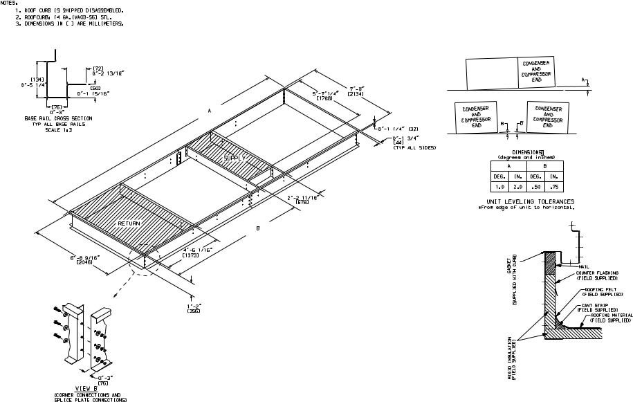
*
13
UNIT TYPE |
DIMENSION |
UNIT SIZE |
UNIT SIZE |
|
030,035 |
040,050 |
|||
|
|
|||
VERTICAL SUPPLY AND RETURN |
A |
21′-81/16″ |
25′-811/16″ |
|
WITH GAS HEAT |
B |
13′-311/16″ |
16′-05/8″ |
|
VERTICAL SUPPLY AND RETURN WITH |
A |
23′-91/4″ |
27′-95/16″ |
|
GAS HEAT AND EXTENDED CHASSIS |
B |
15′-47/16″ |
18′-17/8″ |
Fig. 1 — Roof Curb; Sizes 030-050
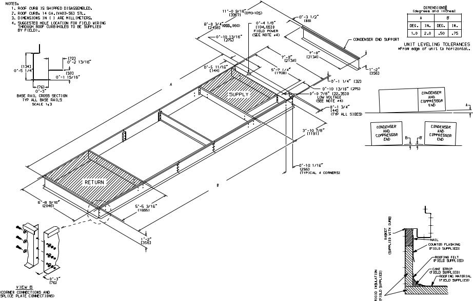
*
14
UNIT TYPE |
DIMENSION |
UNIT SIZE |
|
055-105 |
|||
|
|
||
VERTICAL SUPPLY AND RETURN |
A |
27′-911/16″ |
|
WITH GAS HEAT |
B |
22′-103/16″ |
|
VERTICAL SUPPLY AND RETURN WITH |
A |
29′-107/8″ |
|
GAS HEAT AND EXTENDED CHASSIS |
B |
24′-113/8″ |
Fig. 2 — Roof Curb; Sizes 055-070 and Sizes 075-105 without High-Capacity Power Exhaust

15
Fig. 3 — Roof Curb; Sizes 075-105 with High-Capacity Power Exhaust
*
16
Fig. 4 — Condenser Section Roof Curb (Size 055 and 060 Only)
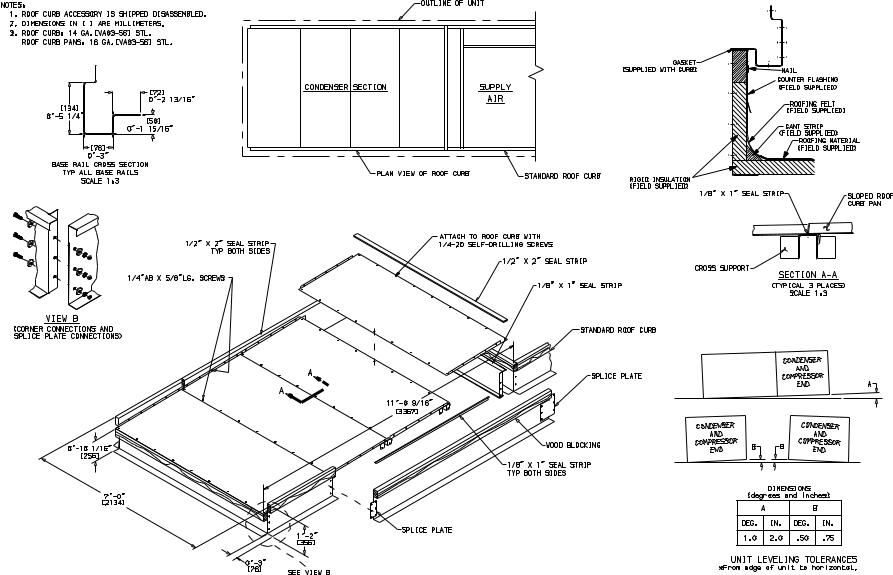
17
*
Fig. 5 — Condenser Section Roof Curb (Size 070-105 Only)
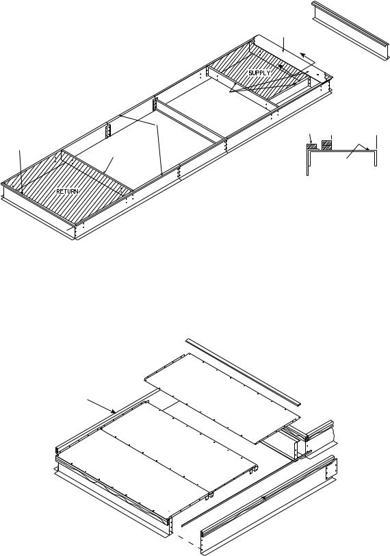
"X"
A
A
CONDENSER
END SUPPORT
4
1
4 REF.
 9 3/4"
2
3
"X"-
NO GASKET
DETAIL A-A
Fig. 6 — Gasket Location on Roof Curb (48ZG,ZN055-105 and 48Z6,Z8075-105 Units)
5
 5
5
Fig. 7 — Gasket Location — Condenser Section Roof Curb (Size 055-105 Units)
18
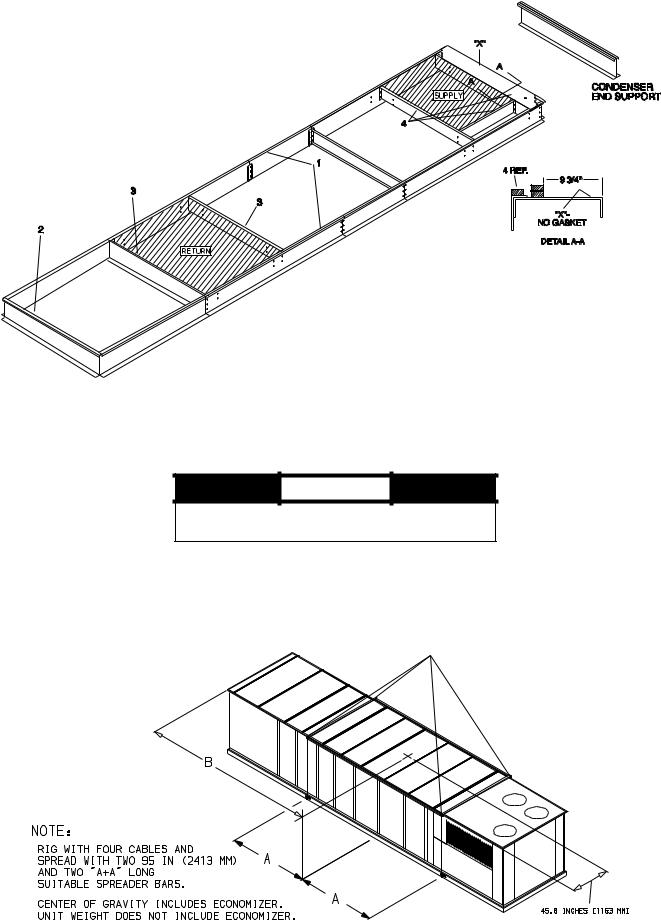
Fig. 8 — Gasket Location on Roof Curb (48ZT,ZW075-105 Units)
 CAUTION
NOTICE TO RIGGERS
1.ALL PANELS MUST BE IN PLACE WHEN RIGGING.
2.DO NOT ATTEMPT TO FORK THESE UNITS.
UNIT |
|
WEIGHT |
A |
|
|
B |
ECONOMIZER |
||||
lb |
|
kg |
in. |
|
mm |
in. |
|
mm |
lb |
kg |
|
|
|
|
|
||||||||
48Z030 |
5770 |
|
2623 |
83.23 |
|
2114 |
176.14 |
|
4474 |
300 |
136 |
48Z035 |
5895 |
|
2679 |
83.23 |
|
2114 |
177.99 |
|
4521 |
300 |
136 |
48Z040 |
6670 |
|
3032 |
92.64 |
|
2353 |
205.87 |
|
5229 |
300 |
136 |
48Z050 |
6710 |
|
3050 |
92.64 |
|
2353 |
207.01 |
|
5258 |
300 |
136 |
Fig. 9 — Rigging Label — Size 030-050 Units (Standard Chassis)
19
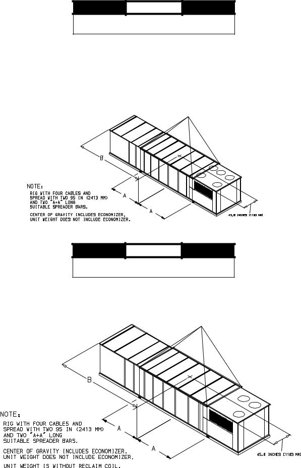
 CAUTION
NOTICE TO RIGGERS
1.ALL PANELS MUST BE IN PLACE WHEN RIGGING.
2.DO NOT ATTEMPT TO FORK THESE UNITS.
UNIT |
WEIGHT |
|
A |
|
|
B |
ECONOMIZER |
|||
lb |
|
kg |
in. |
mm |
in. |
|
mm |
lb |
kg |
|
|
|
|
||||||||
48Z055 |
8,820 |
|
4009 |
128.75 |
3270 |
235.0 |
|
5969 |
530 |
240.9 |
48Z060 |
9,120 |
|
4145 |
128.75 |
3270 |
235.0 |
|
5969 |
530 |
240.9 |
48Z070 |
9,550 |
|
4341 |
112.50 |
2858 |
252.0 |
|
6401 |
530 |
240.9 |
48ZG,ZN075 |
10,445 |
|
4738 |
127.80 |
3247 |
260.6 |
|
6618 |
530 |
240.9 |
48ZG,ZN090 |
10,655 |
|
4833 |
127.80 |
3247 |
262.4 |
|
6666 |
530 |
240.9 |
48ZG,ZN105 |
11,385 |
|
5164 |
127.80 |
3247 |
271.0 |
|
6883 |
530 |
240.9 |
48Z6,Z8075 |
11,915 |
|
5405 |
127.80 |
3247 |
260.6 |
|
6618 |
530 |
240.9 |
48Z6,Z8090 |
12,125 |
|
5500 |
127.80 |
3247 |
262.4 |
|
6666 |
530 |
240.9 |
48Z6,Z8105 |
12,855 |
|
5831 |
127.80 |
3247 |
271.0 |
|
6883 |
530 |
240.9 |
Fig. 10 — Rigging Label — Size 055-105 Units (Standard Chassis)
 CAUTION
NOTICE TO RIGGERS
1.ALL PANELS MUST BE IN PLACE WHEN RIGGING.
2.DO NOT ATTEMPT TO FORK THESE UNITS.
UNIT |
|
WEIGHT |
A |
|
|
B |
ECONOMIZER |
||||
lb |
|
kg |
in. |
|
mm |
in. |
|
mm |
lb |
kg |
|
|
|
|
|
||||||||
48Z030 |
6270 |
|
2844 |
95.83 |
|
2434 |
192.56 |
|
4891 |
300 |
136 |
48Z035 |
6395 |
|
2900 |
95.83 |
|
2434 |
194.72 |
|
4946 |
300 |
136 |
48Z040 |
7170 |
|
3252 |
105.24 |
|
2673 |
222.44 |
|
5650 |
300 |
136 |
48Z050 |
7210 |
|
3270 |
105.24 |
|
2673 |
223.50 |
|
5677 |
300 |
136 |
Fig. 11 — Rigging Label — Size 030-050 Units (Extended Chassis)
20
 CAUTION
NOTICE TO RIGGERS
1.ALL PANELS MUST BE IN PLACE WHEN RIGGING.
2.DO NOT ATTEMPT TO FORK THESE UNITS.
UNIT |
|
WEIGHT |
|
A |
|
B |
ECONOMIZER |
||||
lb |
|
kg |
in. |
|
mm |
in. |
|
mm |
lb |
kg |
|
|
|
|
|
||||||||
48Z055 |
9548 |
|
4330 |
121.50 |
|
3085.5 |
248.50 |
|
6312 |
530 |
240.9 |
48Z060 |
9668 |
|
4385 |
121.50 |
|
3085.5 |
248.50 |
|
6312 |
530 |
240.9 |
Fig. 12 — Rigging Label — Size 055,060 Units (Extended Chassis)
 CAUTION
NOTICE TO RIGGERS
1.ALL PANELS MUST BE IN PLACE WHEN RIGGING.
2.DO NOT ATTEMPT TO FORK THESE UNITS.
UNIT |
|
WEIGHT |
|
A |
||
lb |
|
kg |
in. |
|
mm |
|
|
|
|
||||
48Z075 |
13,380 |
|
6069 |
298.9 |
|
7591 |
48Z090 |
13,590 |
|
6164 |
300.7 |
|
7637 |
48Z105 |
14,320 |
|
6495 |
309.9 |
|
7873 |
Fig. 13 — Rigging Label — 48ZT,ZW075-105 Units (High-Capacity Power Exhaust Units)
21
 Loading...