


48MPD70M
Carrier 48MPD70M, 48MPD82N, 48MPD90P, 48MPD10R, 48MPE62L Installation, Start-up And Service Instructions Manual
...
Installation, Start-Up and Service
Instructions
CONTENTS
Page
GENERAL ................................. 2
SAFETY CONSIDERATIONS ................. 2
INSTALLATION ............................ 3-28
Jobsite Survey ............................. 3
Unit Placement ............................ 3
Roof Mount ................................ 3
Slab Mount ................................ 3
Field-Fabricated Ductwork .................. 3
Rigging .................................... 3
Condensate Drains ......................... 3
Condensate Coil Shipping Covers .......... 3
Install Outdoor Hoods ...................... 3
Make Electrical Connections ................ 14
• POWER SUPPLY
Field Electrical Connections ................ 14
• POWER WIRING
Control Wiring ............................. 17
• SENSORS
• HUMIDITY CONTROL AND HOT WATER
AND STEAM VALVES
• SPACE TEMPERATURE SENSOR (T55)
• SPACE TEMPERATURE SENSOR (T56)
(CV Applications Only)
• SPACE TEMPERATURE AVERAGING
• HEAT INTERLOCK RELAY (VAV Units Only
— Not Necessary For DAV Applications)
• OPTION AND ACCESSORY CONTROL WIRING
Carrier Comfort Network Interface .......... 23
Air Pressure Tubing ........................ 24
Gas Piping (48 Series Units Only) ............26
Installing Flue/Inlet Hoods
(48MP Units Only) .........................26
Fan Isolator Adjustment .................... 27
Check Compressor Mounting ............... 27
Install Accessories ......................... 27
PRE-START-UP ............................28-38
System Check ............................. 28
Compressor Oil ............................ 29
Evaporator-Fan Belts, Pulleys,
and Sheaves .............................. 29
Controls Configuration and Quick Test ...... 35
• SUPPLY FAN STATUS SWITCH (FS)
• CHECK FILTER SWITCH (CFS)
• ENTHALPY CONTROL SET POINT
• KEYPAD AND DISPLAY MODULE (HSIO)
CONFIGURATION
• SET UNIT TYPE
• ENTER JOB SET POINT VALUES
• CONFIGURE UNIT CONTROLS AND
FUNCTIONS
• QUICK TEST FUNCTION
Page
Gas Pressure Check ........................38
Check Supply Fan Rotation ................. 38
START-UP ................................38-42
Initial Check ............................... 38
General .....................................39
Operating Sequences ...................... 39
• SUPPLY FAN
• ECONOMIZER
• COOLING (All Units)
• OCCUPIED COOLING
• UNOCCUPIED COOLING
• OVERRIDES
• ADAPTIVE OPTIMAL START
• ADAPTIVE OPTIMAL STOP
(CV Applications Only)
• GAS HEATING, OPERATION
(48MP Units Only)
Control Loop Checkout ..................... 41
IAQ Control Loop Adjustment ............... 42
Lead/Lag Circuits .......................... 42
Final Checks ............................... 42
CONTROL SYSTEM ........................42-45
General .................................... 42
Components ............................... 42
• PROCESSOR MODULE NO. 1
• PROCESSOR MODULE NO. 2
• HIGH-VOLTAGE RELAY MODULES (DSIO)
• KEYPAD AND DISPLAY MODULE (HSIO)
Default Set Points/Changing Set Points ..... 43
Motor Protection ........................... 43
Variable Frequency Drive (VFD) ............. 43
• DISPLAY AND KEYPAD
SERVICE ..................................45-55
Service Access ............................ 45
• UNIT CONTROL BOX
• COMPRESSORS
• LIQUID SERVICE VALVES, SOLENOID VALVES,
FILTER DRIERS, AND SIGHT GLASSES
• EVAPORATOR-FAN MOTORS, PULLEYS, AND
BELTS
• POWER EXHAUST MOTORS, PULLEYS, AND
BELTS
• GAS HEAT SECTION
• UNIT CONTROL BOX
• ECONOMIZER DAMPER MOTORS
• RETURN-AIR FILTERS
• CONDENSER FANS AND FAN MOTORS
Cleaning .................................. 46
48MPD,MPE62L-10R
50MP62L-10R
Single Package Electric Cooling Units
and Gas Heating/Electric Cooling Units
With Product Integrated Controls
Manufacturer reserves the right to discontinue, or change at any time, specifications or designs without notice and without incurring obligations.
Book 1 1
Tab 1a 1b
PC 111 Catalog No. 534-893 Printed in U.S.A. Form 48/50MP-1SI Pg 1 12-98 Replaces: 50MP-1SI
CONTENTS (cont)
Page
Lubrication ................................ 47
• COMPRESSORS
• FAN SHAFT BEARINGS
• FAN MOTOR BEARINGS
• DOOR HINGES
Coil Cleaning .............................. 47
Refrigerant Circuit ......................... 47
Oil Charge ................................. 49
Moisture/Liquid Indicator ................... 49
Filter Driers ................................ 49
Liquid Line Service Valve ................... 50
Compressor Suction and Discharge
Service Valves ............................ 50
High-Pressure Switch ...................... 50
Low-Pressure Switch ....................... 50
Pressure Relief ............................ 50
Adjustments ............................... 50
• EVAPORATOR FAN AND POWER EXHAUST
MOTOR PLATE
• BELT INSTALLATION AND TENSIONING
• PULLEY ALIGNMENT
Gas Valve Adjustment .......................52
• NATURAL GAS
Page
Main Burners ...............................52
• MAIN BURNER REMOVAL
Protective Devices ......................... 52
• COMPRESSOR PROTECTION
• EVAPORATOR-FAN MOTOR PROTECTION
• CONDENSER-FAN MOTOR PROTECTION
• HIGH- AND LOW-PRESSURE SWITCHES
Variable Frequency Drive (VFD) ............. 53
• SUPPLY FAN VFD
• EXHAUST FAN VFD
• DISPLAYING FAULT SEQUENCE
Control Modules ........................... 53
Processor Module(s) (PSIO) ................ 54
High-Voltage Relay Modules
(DSIO1 and DSIO2) ........................ 54
Refrigerant Feed Components .............. 54
Thermostatic Expansion Valve (TXV) ........ 54
Hot Gas Bypass ........................... 55
Condenser Fans ........................... 55
Compressor Removal ...................... 55
Compressor Replacement .................. 55
TROUBLESHOOTING ......................55-58
START-UP CHECKLIST ..............CL-1 to CL-4
GENERAL
This installation instruction contains base unit installation, start-up, and service instructions only.For complete information on PIC (Product Integrated Controls) controls and
troubleshooting, refer to separate Controls and Troubleshooting literature also enclosed in this literature packet.
IMPORTANT:
1. Tune all loops immediately after starting units. Refer to Control Loop Checkout section on page 40
for more information on tuning loops.
2. The Data Reset function should be performed any
time one or more of the unit factory configuration
values are changed.
3. The HSIO (human sensor input/output) keypad and
display module is required for initial start-up of unit.
All units are shipped in STANDBYmode. The HSIO
must be used to change the unit to RUN mode. The
HSIO is not required for normal operation, however, at any time the unit needs to be transferred
back into STANDYBYmode, such as when servicing a unit, it must be done with the HSIO.
SAFETY CONSIDERATIONS
Installation and servicing of air-conditioning equipment
can be hazardous due to system pressure and electrical components. Only trained and qualified service personnel should
install, repair, or service air-conditioning equipment.
Untrained personnel can perform basic maintenance functions of cleaning coils and filters and replacing filters. All
other operations should be performed by trained service personnel. When working on air-conditioning equipment, observe precautions in the literature, tags and labels attached
to the unit, and other safety precautions that may apply.
Follow all safety codes, including ANSI (American National Standards Institute) Z223.1. Wear safety glasses and
work gloves. Use quenching cloth for unbrazing operations.
Have fire extinguisher available for all brazing operations.
Before performing service or maintenance operations on
unit, turn offmain power switch to unit. Electrical shock
could cause personal injury.
Do not store or use gasoline or other flammable vapors
and liquids in the vicinity of this or any other appliance.
Improper installation, adjustment, alteration, service,
or maintenance can cause injury or property damage.
Refer to this manual. For assistance or additional information, consult a qualified installer or service agency.
This unit uses a microprocessor-based electronic control system. Do not use jumpers or other tools to short
out components, or to bypass or otherwise depart from
recommended procedures. Any short-to-ground of the
control board or accompanying wiring may destroy the
electronic modules or electrical components.
Disconnect gas piping from 48 Series units when leak
testing at pressures greater than 0.5 psig. Pressures greater
than 0.5 psig will cause gas valve damage resulting in
a hazardous condition. If gas valve is subjected to pressure greater than 0.5 psig, it must be replaced. When
pressure testing field-supplied gas piping at pressures of
0.5 psig or less, the unit connected to such piping must
be isolated by manually closing the gas valve.
2
INSTALLATION
Jobsite Survey —
Complete the following checks be-
fore installation.
1. Consult local building codes and the NEC (National
Electrical Code) (ANSI/NFPA [National Fire Protection
Association] 70) for special installation requirements.
2. Determine unit location (from project plans) or select unit
location.
3. Check for possible overhead obstructions which may interfere with unit lifting or rigging.
Do not lift unit with forklift truck. Move unit with
overhead rigging only.
Unit Placement — Inspect unit for transportation dam-
age. File claim with transportation agency.
Provide clearance around and above unit for airflow, safety,
and service access. Do not restrict top (area above condenser fans) in any way. Allow at least 6 ft on all sides for
rated performance, code compliance, and service.
Check unit dimensional drawings for unit arrangement and
minimum performance and service clearances.
Do not install unit in an indoor location. Do not locate air
inlets near exhaust vents or other sources of contaminated
air.
On units equipped with power exhaust option, high
velocity air is exhausted out the hood. Unit should be
positioned with at least 10 ft clearance between the exhaust
hood and any obstruction.Although unit is weatherproof, guard
against water from higher level runoff and overhangs.
Level by using unit frame as a reference. Physical data is
shown in Tables 1-4.
Roof Mount — Check building codes for weight distri-
bution requirements. Unit weight is shown in Table 1. Unit
may be mounted on class A, B, or C roofing material.
ROOF CURB — Assemble and install as described in instructions shipped with the accessory. Accessory roof curb
and information required to field fabricate a roof curb is shown
in Fig. 1 and 2. Install insulation, cant strips, roofing, and
counter flashing as required. For unit condensate drain to function properly, curb must be level or within tolerances shown
in Fig. 1 and 2.
STEEL BEAMS — If roof curb is not used, support unit
with steel beams along its entire length and then support steel
as required. As a minimum, unit must be supported across
its width at each lifting lug location.
Slab Mount — Provide a level concrete slab that ex-
tends beyond unit cabinet at least 6 inches. Make a slab 8 in.
thick with 4 in. above grade. Use gravel apron in front of
condenser coil air inlet to prevent grass and foliage from obstructing airflow. Ensure that slab is of sufficient height to
allow for 7-in. condensate trap.
Field-FabricatedDuctwork — Units are designed for
vertical supply/return only.Field-fabricated ductwork should
be attached to the roof curb. Supply and return duct dimensions are shown in Fig. 1-6.
To attach ductwork to roof curb, insert duct approximately 10 to 11 in. up into roof curb. Connect ductwork to
14-gage roof curb material with sheet metal screws driven
from inside of the duct.
Secure all ducts to the building structure, using flexible
duct connectors between roof curb and ducts as required. Ducts
passing through an unconditioned space must be insulated
and covered with a vapor barrier. Outlet grilles must not lie
directly below unit discharge. The return duct must have a
90-degree elbow before opening into the building space if
unit is equipped with power exhaust.
Design supply duct strong enough to handle expected static
pressures.
For vertical supply and return units, tools or parts could
drop into ductwork and cause an injury. Install 90 degree turns in the supply and return ductwork between
the unit and the conditioned space. If a 90 degree elbow
cannot be installed, then grilles of sufficientstrength and
density should be installed to prevent objects from falling into the conditioned space.
Rigging — Do not drop unit; keep upright. Use spreader
bars over unit to prevent sling or cable damage. Leave condenser coil shipping protection in place while rigging to
prevent coil damage. All lifting lugs MUST be used when
lifting unit.
Level by using unit frame as a reference. See Fig. 7 for
information. Unit and accessory weights are shown in
Tables 1-4. Weight distribution and center of gravity can be
found in Fig. 8.
Condensate Drains — The condensate drain connec-
tion is a 11⁄2-in. NPT pipe connection located on the right
hand side of the unit. See Fig. 9.
NOTE: Use a trap of at least 7-in. deep.
Condenser Coil Shipping Covers — Remove and
discard.
Install Outdoor Hoods
1. Outdoor-air hoods are shipped bolted to the unit in a ship-
ping position. To open hoods, remove the 3 holddown
bars holding the air hood in shipping position. See
Fig. 10.
2. Lift up the highest hood top and swing out hood sides to
form the outside frame of the air hood. Fasten hood top
to hood sides at middle and top holes only,using two screws
on each side. See Fig. 11.
3. Remove the bottom hood block-off plate and set aside.
4. Swing up second hood (from the top of unit) into place
and fasten to hood sides with screws provided using upper hole only.
5. Swing up third hood (from the top of unit) into place and
fasten to hood sides with screws provided using upper
hole only.
6. Swing up fourth hood (bottom hood) into place. Before
fastening hood to hood sides, swing down bottom filter
rack. Fasten hood to hood sides with screws provided using upper hole only.
7. Attach block off plate removed from Step 3.
8. Clip wire tie holding filter track. Swing filter track into
position and fasten to hood sides using screws provided.
Repeat until all 4 filter racks have been installed.
9. Apply a bead of RTVor similar sealant to corner of each
hood at pivot point to prevent water leaks.
Copy continues on page 14.
3
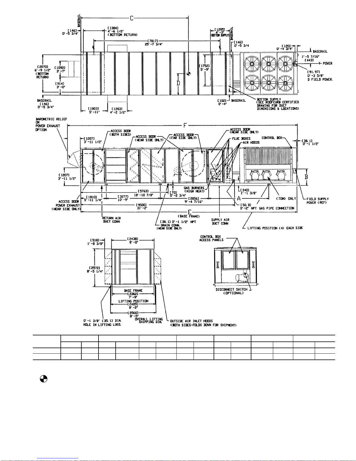
Table 1 — Physical Data
BASE UNIT 48/50MP 62L 70M 82N
NOMINAL CAPACITY (tons) 80 90 105
OPERATING WEIGHT (lb)
Base Unit (48MP/50MP) 16,810/16,550 18,060/17,800 22,660/22,400
Copper Condenser Coils 675 725 725
Exhaust Fan 1,675 1,775 2,375
COMPRESSORS Semi-Hermetic
Number of Refrigerant Circuits 22 2
Circuit (No. of Cylinders) A (6) B (6) A1 (6), A2 (4) B (6) A1 (6), A2 (4) B1 (6), B2 (6)
Model 06E −299 −299 −275, −250 −299 −265, −250 −265, −265
Oil Charge (pints) 19 19 19, 14 19 19, 14 19,19
Capacity Steps (%) 17,33,50,67,83,100 11,22,33,41,56,67,78,89,100 18,26,35,44,53,56,65,74,82,91,100
REFRIGERANT R-22
Operating Charge (lb), Sys 1/Sys 2 (Standard Coil) 78/78 85/82 85/82
Operating Charge (lb), Sys 1/Sys 2 (Alternate Coil) 83/83 94/85 92/88
CONDENSER COILS Grooved Tube (
3
⁄8-in. OD)
Quantity 44 4
Rows...Fins/in. 3...17 3...17 3...17
Total Face Area (sq ft) 116.7 128.3 128.3
EVAPORATOR COILS Smooth Tube (
5
⁄8-in. OD)
Quantity 22 2
Rows...Fins/in.
Standard 3...14 3...14 3...14
Alternate 4...14 4...14 4...14
Total Face Area (sq ft) 62.6 70.0 82.0
Refrigerant Feed
Device...No. per Circuit TXV...2 TXV...2 TXV...2
EVAPORATOR FANS
Forward Curved Fan
Motor Hp 30 40 40 50 40 50
Motor Frame Size 286T 324T 324T 326T 324T 326T
Efficiency at Full Load (%)
Standard Efficiency 92.4 93.0 93.0 93.0 93.0 93.0
High Efficiency 93.6 94.5 94.5 94.5 94.5 94.5
Fan Pulley Pitch Diameter (in.) 18.4 16.0 15.4 15.4 20.0 18.4
Motor Pulley Pitch Diameter (in.) 6.2 6.4 5.6 6.4 5.8 6.0
Fan Rpm 608 705 658 747 526 590
Belts Quantity...Model No. 3...BX128 4...BX124 5...BX124 5...BX124 5...BX115 6...BX112
Center Distance Range (in.) 42.1-46.1 43.1-48.2 43.1-48.2 43.1-48.2 35.4-40.2 35.4-40.2
Maximum Rpm 835 835 835 835 715 715
Air Foil Fan
Motor Hp 30 40 40 50 40 50
Motor Frame Size 286T 324T 324T 326T 324T 326T
Efficiency at Full Load (%)
Standard Efficiency 92.4 93.0 92.4 93.0 92.4 93.0
High Efficiency 93.6 94.5 93.6 94.5 93.6 94.5
Fan Pulley Pitch Diameter (in.) 11.0 12.4 12.4 9.1 12.5 12.5
Motor Pulley Pitch Diameter (in.) 7.4 9.4 9.4 7.5 6.9 7.5
Fan Rpm 1192 1337 1337 1442 966 1050
Belts Quantity...Model No. 3...B111 3...B120 3...B120 3...5VX1120 3...5VX1060 3...5VX1060
Center Distance Range (in.) 39.7-43.7 40.4-45.2 40.4-45.2 40.4-45.2 35.4-39.4 35.4-39.4
Maximum Rpm 1595 1595 1595 1595 1298 1298
Air Foil Fan (cont)
Motor Hp 50 60 60
Motor Frame Size 326T 364T 364T
Efficiency at Full Load (%)
Standard Efficiency 93.0 94.5 94.5
High Efficiency 94.5 95.4 95.4
Fan Pulley Pitch Diameter (in.) 9.1 8.1 11.0
Motor Pulley Pitch Diameter (in.) 7.5 7.1 7.1
Fan Rpm 1442 1534 1119
Belts Quantity...Model No. 3...5VX1120 4...5VX1080 4...5VX1030
Center Distance Range (in.) 40.4-45.2 39.4-44.9 34.4-39.1
Maximum Rpm 1595 1595 1298
CONDENSER FANS
Quantity...Diameter (in.) 6...30 6...30 6...30
Nominal Cfm 52,000 52,000 52,000
Motor Hp...Rpm 1...1140 1...1140 1...1140
SUPPLY FAN Forward Curve Airfoil Forward Curve Airfoil Forward Curve Airfoil
Nominal Cfm 32,000 32,000 36,000 36,000 42,000 42,000
Size (in.) 30.0 33.0 30.0 33.0 36.0 40.25
Maximum Allowable Rpm 835 1595 835 1595 715 1298
Shaft Diameter at Pulley (in.) 2.69 2.44 2.69 2.44 2.69 2.44
FURNACE SECTION (48MP Units Only)
Rollout Switch Cutout Temp (F) 190 190
Number of Burners 77
Burner Orifice Diameter (in. ...drill size) 0.136...29 0.136...29
Gas Input (Btuh) 342,000 342,000
Manifold Pressure (in. wg) — Natural Gas 3.3 3.3
Gas Valve Input Pressure Range
in. wg 5.5-13.5 5.5-13.5
psig 0.235-0.487 0.235-0.487
LOW HEAT (48MPD)/HIGH HEAT (48MPE)
Number of Sections 2/3 2/3
Gas Input (Btuh) Stage 1 515,000/770,000 515,000/770,000
Stage 2 685,000/1,025,000 685,000/1,025,000
Efficiency (Steady State %) 81/81 81/81
Temperature Rise Range (F) 10-40/20-50 5-35/10-40
Minimum Heating Airflow (cfm) 12,850/15,400 14,700/19,250
Field Gas Connection Size (in.) 22
FILTERS
Medium Efficiency (30%)
Pleated (Standard)
Quantity...Size (in.)
15...24 x 24 x 2,
5...24 x 12 x 2
15...24 x 24 x 2,
5...24 x 12 x 2
20...24 x 24 x 2,
5...24 x 12 x 2
High Efficiency (90%) Cartridge Filters
with Prefilters (Optional)
Quantity...Size (in.)
15...24 x 24 x 4,
5...24 x 12 x 4
15...24 x 24 x 4,
5...24 x 12 x 4
20...24 x 24 x 4,
5...24 x 12 x 4
Outdoor Air Inlet Screens Cleanable Aluminum
Quantity...Size (in.) 16...20 x 25 x 1 16...20 x 25 x 1 24...20 x 25 x 1
LEGEND
TXV — Thermostatic Expansion Valve
4
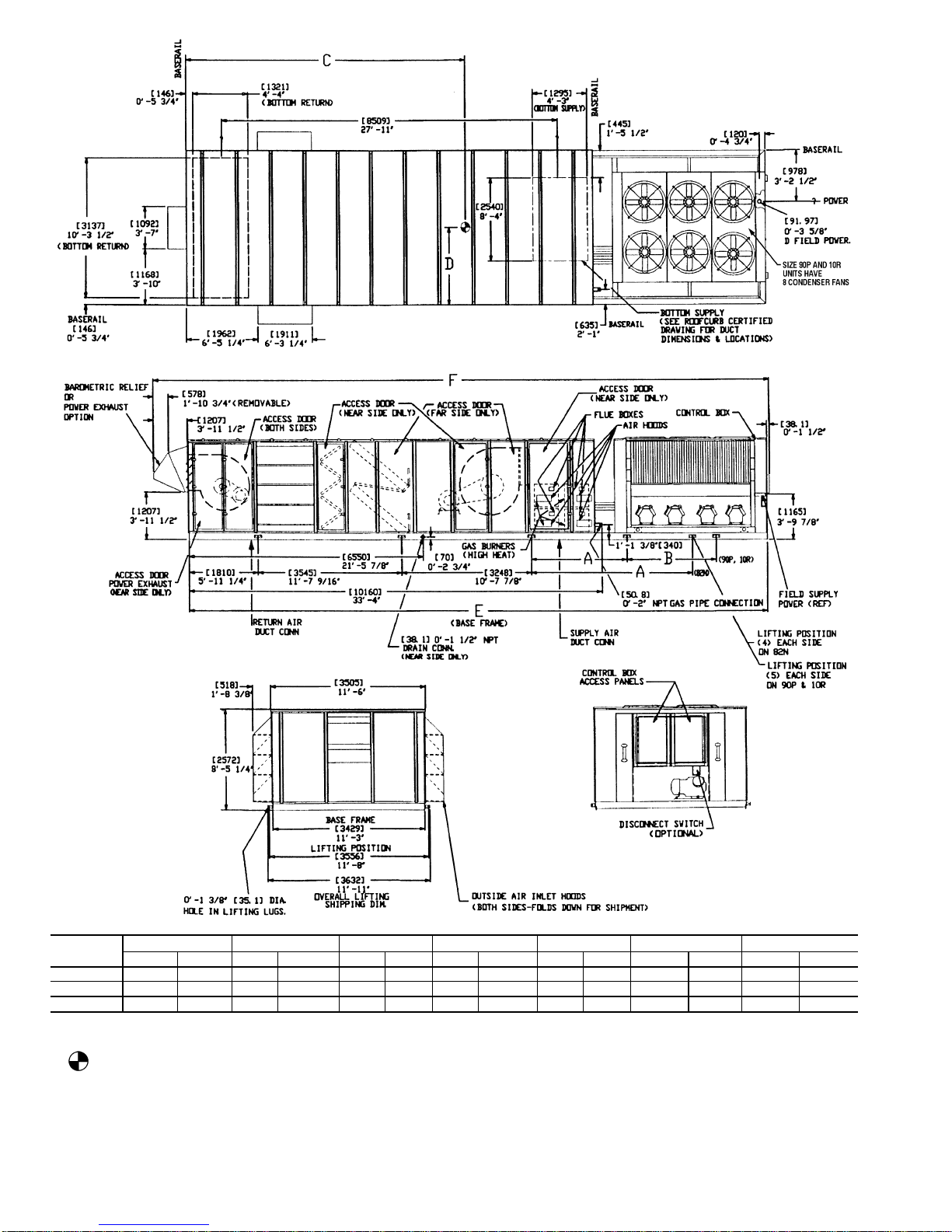
Table1 — Physical Data (cont)
BASE UNIT 48/50MP 90P 10R
NOMINAL CAPACITY (tons) 115 120
OPERATING WEIGHT (lb)
Base Unit (48MP/50MP) 24,660/24,750 25,110/25,100
Copper Condenser Coils 950 950
Exhaust Fan 2400 2400
COMPRESSORS Semi-Hermetic
Number of Refrigerant Circuits 22
Circuit (No. of Cylinders) A1 (6), A2 (6) B1 (6), B2 (6) A1 (6), A2 (6) B1 (6), B2 (6)
Model 06E −265, −275 −265, −275 −265, −299 −265, −275
Oil Charge (pints) 19, 19 19, 19 19, 19 19, 19
Capacity Steps (%) 15,23,30,38,45,58,65,73,85,92,100 14,21,28,35,42,61,68,75,86,93,100
REFRIGERANT R-22
Operating Charge (lb), Sys 1/Sys 2 (Standard Coil) 85/85 86/87
Operating Charge (lb), Sys 1/Sys 2 (Alternate Coil) 93/93 93/96
CONDENSER COILS Grooved Tube (
3
⁄8-in. OD)
Quantity 44
Rows...Fins/in. 3...17 3...17
Total Face Area (sq ft) 168.0 168.0
EVAPORATOR COILS Smooth Tube (
5
⁄8-in. OD)
Quantity 22
Rows...Fins/in.
Standard 3...14 3...14
Alternate 4...14 4...14
Total Face Area (sq ft) 90.3 101.4
Refrigerant Feed
Device...No. per Circuit TXV...2 TXV...2
EVAPORATOR FANS
Forward Curved Fan
Motor Hp 50 60 60
Motor Frame Size 326T 364T 364T
Efficiency at Full Load (%)
Standard Efficiency 93.0 94.5 94.5
High Efficiency 94.5 95.4 95.4
Fan Pulley Pitch Diameter (in.) 18.8 18.8 21.3
Motor Pulley Pitch Diameter (in.) 5.9 6.7 6.7
Fan Rpm 555 630 556
Belts Quantity...Model No. 4...5VX1120 4...5VX1120 4...5VX1150
Center Distance Range (in.) 35.4/40.2 35.4/40.2 34.2/40.2
Maximum Rpm 715 715 715
Air Foil Fan
Motor Hp 50 60 50 60
Motor Frame Size 326T 364T 326T 364T
Efficiency at Full Load (%)
Standard Efficiency 93.0 94.5 93.0 94.5
High Efficiency 94.5 95.4 94.5 95.4
Fan Pulley Pitch Diameter (in.) 12.5 13.7 13.7 13.7
Motor Pulley Pitch Diameter (in.) 7.5 8.7 8.1 8.7
Fan Rpm 1050 1111 1035 1111
Belts Quantity...Model No. 3...5VX1030 3...5VX1060 3...5VX1060 3...5VX1060
Center Distance Range (in.) 35.4/39.4 34.4/39.1 35.4/39.4 34.4/39.1
Maximum Rpm 1298 1298 1298 1298
Air Foil Fan (cont)
Motor Hp 75 75
Motor Frame Size 365T 365T
Efficiency at Full Load (%)
Standard Efficiency 95.4 95.4
High Efficiency ——
Fan Pulley Pitch Diameter (in.) 16.1 16.1
Motor Pulley Pitch Diameter (in.) 11.1 11.1
Fan Rpm 1207 1207
Belts Quantity...Model No. 3...5VX1120 3...5VX1120
Center Distance Range (in.) 34.4/39.1 34.4/39.1
Maximum Rpm 1298 1298
CONDENSER FANS
Quantity...Diameter (in.) 8...30 8...30
Nominal Cfm 69,500 69,500
Motor Hp...Rpm 1...1140 1...1140
SUPPLY FAN Forward Curve Airfoil Forward Curve Airfoil
Nominal Cfm 46,000 46,000 52,000 52,000
Size (in.) 36.0 40.25 36.0 40.25
Maximum Allowable Rpm 715 1298 715 1298
Shaft Diameter at Pulley (in.) 2.69 2.44 2.69 2.44
FURNACE SECTION (48MP Units Only)
Rollout Switch Cutout Temp (F) 190
Number of Burners 7
Burner Orifice Diameter (in. ...drill size) 0.136...29
Gas Input (Btuh) 342,000
Manifold Pressure (in. wg) — Natural Gas 3.3
Gas Valve Input Pressure Range
in. wg 5.5-13.5
psig 0.235-0.487
LOW HEAT (48MPD)/HIGH HEAT (48MPE)
Number of Sections 2/3
Gas Input (Btuh) Stage 1 515,000/770,000
Stage 2 685,000/1,025,000
Efficiency (Steady State %) 81/81
Temperature Rise Range (F) 5-35/10-40
Minimum Heating Airflow (cfm) 14,700/19,250
Field Gas Connection Size (in.) 2
FILTERS
Medium Efficiency (30%)
Pleated (Standard) Quantity...Size (in.)
20...24 x 24 x 2,
5...24 x 12 x 2
20...24 x 24 x 2,
5...24 x 12 x 2
High Efficiency (90%)
Cartridge Filters with Prefilters (Optional)
Quantity...Size (in.)
20...24 x 24 x 4,
5...24 x 12 x 4
20...24 x 24 x 4,
5...24 x 12 x 4
Outdoor Air Inlet Screens Cleanable Aluminum
Quantity...Size (in.) 24...20 x 25 x 1 24...20 x 25 x 1
LEGEND
TXV — Thermostatic Expansion Valve
5
Table 2 — Optional Power Exhaust Specifications
UNIT 48/50MP 62L 70M 82N
Type 100% Mod 100% Non Mod 100% Mod 100% Non Mod 100% Mod 100% Non Mod
Motor Hp 30 30 40 40 40 40
Motor Frame Size 286T 286T 324T 324T 324T 324T
Efficiency at Full Load (%)
Standard Efficiency 92.4 92.4 93.0 93.0 93.0 93.0
High Efficiency 93.6 93.6 94.5 94.5 94.5 94.5
Fan Pulley Pitch Diameter (in.) 18.4 18.4 18.4 18.4 25.0 20.0
Motor Pulley Pitch Diameter (in.) 5.6 6.0 6.2 6.6 6.8 5.8
Fan Rpm 552 590 608 646 491 526
Belts Quantity...Model No. 4...BX80 4...BX81 5...BX80 5...BX80 5...B90 5...BX90
Center Distance Range (in.) 19.9-23.3 19.9-23.3 18.6-22.8 18.6-22.8 21.8-25.9 21.8-25.9
Maximum Allowable Rpm 650 650 835 835 560 560
Type 50% Non Mod 50% Non Mod 50% Non Mod
Motor Hp 7.5 7.5 7.5
Motor Frame Size 213T 213T 213T
Efficiency at Full Load (%)
Standard Efficiency 88.5 88.5 88.5
High Efficiency 91.7 91.7 91.7
Fan Pulley Pitch Diameter (in.) 15.4 16.0 18.4
Motor Pulley Pitch Diameter (in.) 3.6 3.6 3.6
Fan Rpm 412 397 346
Belts Quantity...Model No. 2...BX75 2...BX77 2...BX90
Center Distance Range (in.) 21.3-24.1 21.7-24.2 24.9-27.4
Maximum Allowable Rpm 690 650 600
Table 2 — Optional Power Exhaust Specifications (cont)
UNIT 48/50MP 90P 10R
Type 100% Mod 100% Non Mod 100% Mod 100% Non Mod
Motor Hp 50 50 60 60
Motor Frame Size 326T 326T 364T 364T
Efficiency at Full Load (%)
Standard Efficiency 93.0 93.0 94.5 94.5
High Efficiency 94.5 94.5 95.4 95.4
Fan Pulley Pitch Diameter (in.) 28.1 28.1 28.1 28.1
Motor Pulley Pitch Diameter (in.) 8.1 8.1 9.1 9.1
Fan Rpm 508 508 558 558
Belts Quantity...Model No. 3...5VX1060 3...5VX1060 3...5VX1060 3...5VX1060
Center Distance Range (in.) 21.8/25.9 21.8/25.9 20.9/25.6 20.9/25.6
Maximum Allowable Rpm 560 560 560 560
Type 50% Non Mod 50% Non Mod
Motor Hp 10 15
Motor Frame Size 215T 254T
Efficiency at Full Load (%)
Standard Efficiency 89.5 89.5
High Efficiency 91.7 91.7
Fan Pulley Pitch Diameter (in.) 20.0 20.0
Motor Pulley Pitch Diameter (in.) 4.5 4.0
Fan Rpm 362 371
Belts Quantity...Model No. 2...BX90 3...BX90
Center Distance Range (in.) 24.9/27.4 23.9/26.8
Maximum Allowable Rpm 600 600
Table 3 — Compressor Oil Charge
UNIT 48/50MP
OIL CHARGE (pints)
Compressor
Circuit A
Total Circuit A
Compressor
Circuit B
Total Circuit B
A1 A2 B1 B2
62L 19 — 19 19 — 19
70M 19 14 33 19 — 19
82N 19 14 33 19 19 38
90P 19 19 38 19 19 38
10R 19 19 38 19 19 38
Table4—Variable Frequency Drive (VFD) Physical Data
FAN MOTOR
HP
DIMENSIONS (in.)
WEIGHT (lb)
Height Width Length
30 24.02 12.99 11.22 68
40 24.02 12.99 11.22 68
50 30.91 12.99 11.22 106
60 30.91 12.99 11.22 106
75 33.46 12.99 11.22 106
6
NOTES:
1. Roof curb is shipped disassembled.
2. Roof curb: 14 gage [VA03-56] steel.
3. Dimensions in [ ] are in millimeters.
4. Toprevent standing water in the drain pan of the
indoor section, roof curb and unit must be level
within tolerances shown.
NOTES:
1. Toprevent the hazard of stagnant water build-up in the drain pan on the indoor section, unit cannot
exceed leveling tolerances shown.
2. If a Carrier roof curb is not used, curb cross rails must be postioned to clear unit base rail locations
shown.
Fig. 1 — Roof Curb Dimensions, 48/50MP62L and 70M
7
NOTES:
1. Roof curb is shipped disassembled.
2. Roof curb: 14 gage [VA03-56] steel.
3. Dimensions in [ ] are in millimeters.
4. Toprevent standing water in the drain pan of the
indoor section, roof curb and unit must be level
within tolerances shown.
NOTES:
1. Toprevent the hazard of stagnant water build-up in the drain pan on the indoor section, unit cannot
exceed leveling tolerances shown.
2. If a Carrier roof curb is not used, curb cross rails must be postioned to clear unit base rail locations
shown.
Fig. 2 — Roof Curb Dimensions, 48/50MP82N-10R
8
UNIT SIZE
48MPD,E
WEIGHT A B C D E F
lb kg mm ft-in. mm ft-in. mm ft-in. mm ft-in. mm ft-in. mm ft-in.
62L 16,810 7624 3505 11- 6 957 3-1
11
⁄
16
5909 19-45⁄81203 3-113⁄813 011 42-81⁄414 256 46-91⁄
4
70M 18,060 8190 3647 11-119⁄161165 3-97⁄86166 20-23⁄41264 4- 13⁄413 297 43-71⁄214 542 47-81⁄
2
NOTES:
1. Dimensions in [ ] are in millimeters.
2. Centerof gravity includes exhaust fan and high heat options. Unitweight does not include exhaust fan or high
heat options.
3. High heat add: 260 lb [118 kg]
Exhaust fan add: 1675 lb [761 kg] on 62L
1775 lb [807 kg] on 70M
4. Unit clearances:
Top — Do not restrict condenser fans, control box end — 68-09.
Sides — 68-09 (except on return fan equipped units — 108-09).
Economizer end — 68-09 (except power exhaust units — 108-09).
For smaller service and operational clearances, contact Carrier Application Engineering Department.
5. Downshot ducts designed to be attached to accessory roof curb. If unit is mounted on dunnage, it is recommended
the ducts be supported by cross braces as done on the accessory roof curb.
Fig. 3 — Base Unit Dimensions, 48MP62L, 70M
9
UNIT SIZE
48MPD,E
WEIGHT A B C D E F
lb kg mm ft-in. mm ft-in. mm ft-in. mm ft-in. mm ft-in. mm ft-in.
82N 22,660 10 295 3646 11-11
9
⁄
16
— — 6734 22- 11⁄81753 5-9 13 957 45-91⁄215 202 49-101⁄
2
90P 24,660 11 203 1938 6- 45⁄
16
2572 8-51⁄47283 23-103⁄41765 5-91⁄214 821 48-71⁄216 066 52- 81⁄
2
10R 25,110 11 408 1938 6- 45⁄
16
2572 8-51⁄47268 23-101⁄81759 5-91⁄414 821 48-71⁄216 066 52- 81⁄
2
NOTES:
1. Dimensions in [ ] are in millimeters.
2. Center of gravity includes exhaust fan and high heat options. Unit weight
does not include exhaust fan or high heat options.
3. High heat add: 260 lb [118 kg]
Exhaust fan add: 2275 lb [1034 kg] on 82N
2400 lb [1090 kg] on 90P and 10R
4. Unit clearances:
Top — Do not restrict condenser fans, control box end — 68-09.
Sides — 68-09 (except on return fan equipped units — 108-09).
Economizer end — 68-09 (except power exhaust units — 108-09).
For smaller service and operational clearances, contact Carrier Application Engineering Department.
5. Downshot ducts designedto be attachedto accessory roof curb.If unit ismounted
on dunnage, it is recommended the ducts be supported by cross braces as done
on the accessory roof curb.
Fig. 4 — Base Unit Dimensions, 48MP82N-10R
10
UNIT
SIZE
50MP
WEIGHT
(See Note 3)
AB
C1
(See Note 2)C2(See Note 2)
DE F
lb kg mm ft-in. mm ft-in. mm ft-in. mm ft-in. mm ft-in. mm ft-in. mm ft-in.
62L 16,550 7511 3505 118-69 957 38-1
11
⁄169 5880 198-31⁄29 6325 208-99 1203 38-113⁄89 13 011 428-81⁄49 14 256 468-91⁄
4
9
70M 17,800 8078 3647 118-11
9
⁄169 1165 38-97⁄86166 208-23⁄46649 218-93⁄49 1264 48-13⁄49 13 297 438-71⁄29 14 542 478-81⁄
2
9
NOTES:
1. Dimensions in [ ] are in millimeters.
2. Center of gravity. Use appropriate column for units with or without
exhaust fan option.
3. Unit weight does not include exhaust fan option.
Exhaust fan add: 1675 lb [761 kg] on 62L
1775 lb [807 kg] on 70M
4. Unit clearances:
Top — Do not restrict condenser fans.
Sides — 68-09
Economizer End — 68-09 (Except power exhaust units 108-09).
Control Box End — 68-09
For smaller service and operational clearances, contact Carrier Application
Engineering department.
5. Downshot ducts designed to be attached to accessory roof curb. If unit is
mounted on dunnage, it is recommended the ducts be supported by cross
braces as done on the accessory roof curb.
6. All lifting lugs must be used when rigging unit.
Fig. 5 — Base Unit Dimensions, 50MP62L and 70M
11
UNIT
SIZE
50MP
WEIGHT
(See Note 3)
AB
C1
(See Note 2)
C2
(See Note 2)
DE F
lb kg mm ft-in. mm ft-in. mm ft-in. mm ft-in. mm ft-in. mm ft-in. mm ft-in.
82N 22,400 10 295 3646 118-11
9
⁄169 — — 6702 218-117⁄89 7180 238-611⁄169 1753 58-99 13 957 458-91⁄29 15 202 498-101⁄
2
9
90P 24,750 11 375 1938 68-4
5
⁄169 2572 88-51⁄47383 238-103⁄47787 258-69⁄169 1765 58-91⁄29 14 821 488-71⁄29 16 066 528-81⁄
2
9
10R 25,100 11 536 1938 68-4
5
⁄169 2572 88-51⁄47383 238-101⁄87793 258-613⁄169 1759 58-91⁄49 14 821 488-71⁄29 16 066 528-81⁄
2
9
NOTES:
1. Dimensions in [ ] are in millimeters.
2. Center of gravity.Use appropriate column for units with or without exhaust fan option.
3. Unit weight does not include exhaust fan option.
Exhaust fan add: 2275 lb [1034 kg] on 82N
2300 lb [1090 kg] on 90R and 10R
4. Unit clearances:
Top — Do not restrict condenser fans.
Sides — 68-09
Economizer End — 68-09 (Except power exhaust units 108-09).
Control Box End — 68-09
For smaller service and operational clearances, contact Carrier Application
Engineering department.
5. Downshot ducts designed to be attached to accessory roof curb. If unit is
mounted on dunnage, it is recommended the ducts be supported by cross
braces as done on the accessory roof curb.
6. All lifting lugs must be used when rigging unit.
Fig. 6 — Base Unit Dimensions, 50MP82N-10R
12
NOTICE TO RIGGERS
UNIT
SIZE
WEIGHT
ABCDE
Unit 48MP Unit 50MP Exhaust Fan
lb kg lb kg lb kg in. mm in. mm in. mm in. mm in. mm
62L 16,810 7 624 16,550 7 507 1675 760 71.25 1810 129.00 3277 112.44 2856 138.00 3505 N/A N/A
70M 18,060 8 190 17,800 8 074 1775 805 71.25 1810 129.00 3277 112.44 2856 143.56 3646 N/A N/A
82N 22,660 10 295 22,400 10 161 2275 1032 71.25 1810 139.56 3545 127.87 3248 143.56 3646 N/A N/A
90P 24,660 11 203 24,750 11 227 2400 1089 71.25 1810 139.56 3545 127.87 3248 177.56 4510 101.25 2572
10R 25,110 11 408 25,100 11 385 2400 1089 71.25 1810 139.56 3545 127.87 3248 177.56 4510 101.25 2572
NOTE: All lifting lugs must be used when rigging with eight or ten
cables and spread with four or five 95 in. (2413 mm) and two
‘‘B+C+D’’long suitable spreader bars. Unit weight does not include
exhaust fan option.
1. All panels must be in place when rigging.
2. Unit is not designed for handling by fork truck.
Fig. 7 — Rigging Label
A
4
1
3
2
B
UNIT
48MP
CORNER WEIGHT (lb) DIMENSIONS (ft-in.)
1234 A B
62L 5095 5000 4339 4051 19- 4
5
⁄
8
3-113⁄
8
70M 5337 5338 5290 3969 20- 23⁄
4
4- 13⁄
4
82N 6614 6326 6444 5651 22- 11⁄
8
5- 9
90P 7156 6789 7330 6226 23-10
3
⁄
4
5- 91⁄
2
10R 7174 6897 7345 6254 23-101⁄
8
5- 91⁄
4
UNIT
50MP
CORNER WEIGHT (lb) DIMENSIONS (ft-in.)
1234 A B
62L 4237 3967 5038 4933 19- 3
1
⁄
2
3-113⁄
8
70M 5258 3955 5185 5167 20- 23⁄
4
4- 13⁄
4
82N 6351 5571 6574 6279 21-117⁄
8
5- 9
90P 7211 6132 7045 6761 23-10
3
⁄
4
5- 91⁄
2
10R 7288 6196 7195 6820 23-101⁄
8
5- 91⁄
4
Fig. 8 — Unit Center of Gravity and Corner Weights
13
Make Electrical Connections
POWER SUPPLY — Electrical characteristics of available
power supply must agree with unit nameplate rating. Supply
voltage must be within the limits shown in Table 5.
Field Wire Routing — Field wiring is brought into the unit
through the bottom of the control box.
A3
5
⁄8-in. hole for field power wiring and a7⁄8-in. hole for
24-v control wiring are provided in the bottom of the control
box. Field-supplied couplings must be used when routing wiring into the control box.
Field Electrical Connections
IMPORTANT: The 48/50MP units generate, use, and
can radiate radio frequency energy. If units are not installed and used in accordance with these instructions,
they may cause radio interference. They have been tested
and found to comply with limits of a Class A computing device as defined by FCC (Federal Communications Commission) regulations, Subpart J of Part 15,
which are designed to provide reasonable protection
against such interference when operated in a commercial environment.
POWER WIRING — Units are factory wired for 460-v as
shown on the unit nameplate. The main terminal block is
suitable for use with aluminum or copper wires. Maximum
wire size is 500 MCM.
Branch circuit for power supply to unit must be protected
against ground fault or short circuit. Provide an overcurrent
protection device in the branch circuit. The MOCP (Maximum Overcurrent Protection) value for this device is shown
on unit informative data plate.
When installing units, provide and install a unit safety disconnect per NEC of adequate size. Refer to Electrical Data
tables for disconnect sizing. Disconnect may incorporate branch
circuit fusing (if local or national codes permit) but combination disconnect fuse is not required. Disconnect must be
able to be locked OFF.
PITCH DRAIN LINE
TO OFFSET LINE
FRICTION
7" MIN.
2" MIN.
SEALANT
SLAB
UNIT
BASE
RAIL
SLAB MOUNT DRAIN
Fig. 9 — Condensate Drain Piping Details
HOLD
DOWN
BARS
Fig. 10 — Outdoor Air Hoods Shipping Position
HOOD
SIDE
HOOD
TOP
FILTER
RACK
BLOCK-OFF
PLATE
Fig. 11 — Outdoor Air Hoods Installed
14
Disconnect must be located within sight of the unit and readily accessible from the unit in compliance with NEC
Article 440-14.
All field wiring must comply with NEC and all local codes.
Size wire based on MCA (Minimum Circuit Amps) value
shown on the unit informative plate. See Fig. 12 for power
wiring connections to the unit power terminal block and equipment ground.
Operating voltage to the compressor must be within the voltage range indicated on the unit nameplate. Voltages between
phases must be balanced within 2%, and the current must be
balanced within 10%. See Table 5 for unit electrical data.
Use the following formula to determine the percent voltage
imbalance.
% Voltage Imbalance
max voltage deviation from average voltage
= 100 x
average voltage
EXAMPLE: Supply voltage is 460-3-60.
AB = 452 v
BC = 464 v
AC = 455 v
452 + 464 + 455
Average Voltage =
3
1371
=
3
457
=
Determine maximum deviation from average voltage:
(AB) 457 − 452 = 5 v
(BC) 464 − 457 = 7 v
(AC) 457 − 455 = 2 v
Maximum deviation is 7 v.
Determine percent voltage imbalance:
7
% Voltage Imbalance = 100 x
457
= 1.53%
This amount of phase imbalance is satisfactory as it is be-
low the maximum allowable 2%.
IMPORTANT: If the supply voltage phase imbalance
is more than 2%, contact local utility immediately.
Unit failure as a result of operation on improper line voltage or excessive phase imbalance constitutes abuse and may
cause damage to electrical components.
LEGEND
EQUIP — Equipment
GND — Ground
NEC — National Electrical Code
TB — Terminal Block
Fig. 12 — Field Power Wiring Connections
15
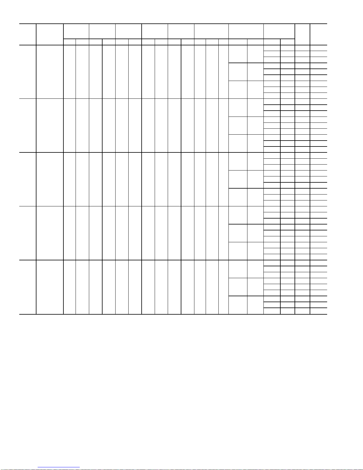
Table 5 — Electrical Data
UNIT
48MP/
50MP
VOLTAGE
3 Ph, 60 Hz
VOLTAGE
RANGE
COMP
NO. A1
COMP
NO. A2
COMP
NO. B1
COMP
NO. B2
CONDENSER
FAN
MOTORS
EVAPORATOR
FAN MOTOR
POWER
EXHAUST
FAN MOTOR
MCA MOCP
Min Max RLA LRA RLA LRA RLA LRA RLA LRA Qty FLA Hp FLA Hp FLA Hp
62L 460 414 508 65.4 345 — — 65.4 345 — — 6 3.3 1
40 30
— — 207.0 250
11 7.5 218.0 250
40 30 247.0 300
52 40
— — 219.0 250
11 7.5 230.0 250
40 30 259.0 300
65 50
— — 232.0 250
11 7.5 243.0 300
40 30 272.0 300
70M 460 414 508 46.8 253 34.6 173 65.4 345 — — 6 3.3 1
52 40
— — 235.0 300
11 7.5 246.0 300
52 40 287.0 350
65 50
— — 248.0 300
11 7.5 259.0 300
52 40 300.0 350
77 60
— — 262.9 300
11 7.5 273.9 350
52 40 314.9 350
82N 460 414 508 43.6 223 34.6 173 43.6 223 43.6 223 6 3.3 1
52 40
— — 250.2 300
11 7.5 261.2 300
52 40 302.2 350
65 50
— — 266.5 300
11 7.5 277.5 300
52 40 318.5 350
77 60
— — 281.5 350
11 7.5 292.5 350
52 40 333.5 400
90P 460 414 508 43.6 223 46.8 253 43.6 223 46.8 253 8 3.3 1
65 50
— — 288.5 350
14 10 302.5 350
65 50 353.5 350
77 60
— — 303.5 350
14 10 317.5 350
65 50 368.5 400
96 75
— — 327.5 400
14 10 341.5 400
65 50 392.2 450
10R 460 414 508 43.6 223 65.4 345 43.6 223 46.8 253 8 3.3 1
65 50
— — 307.2 350
14 15 321.1 350
77 60 387.1 450
77 60
— — 322.1 350
14 15 336.1 400
77 60 399.1 450
96 75
— — 345.8 400
14 15 359.8 450
77 60 422.8 500
LEGEND
COMP — Compressor
FLA — Full Load Amps
Hp — Nominal Horsepower
LRA — Locked Rotor Amps
MCA — Minimum Circuit Amps (for wire sizing)
MOCP — Maximum Overcurrent Protection
RLA — Rated Load Amps
16
Control Wiring — See Fig. 13 for sensor wiring con-
nections to main and auxiliary control boxes. The recommended types of control wiring for 48/50MP unit devices
are shown in Table 6.
Table 6 — Recommended Sensor and
Device Non-Shielded Cable
MANUFACTURER
PART NO.
Regular Wiring Plenum Wiring
Alpha 1895 —
American A21451 A48301
Belden 8205 884421
Columbia D6451 —
Manhattan M13402 M64430
Quabik 6130 —
SENSORS — Sensors should be wired using single twisted
pairs of 20AWG(American Wire Gage) conductor cable rated
for the application, except for the T56 accessory sensor which
requires 3-conductor cable.
NOTE: Humidity and CO2sensors must be powered from
isolated 24-v power supplies.
HUMIDITY CONTROLAND HOT WATER AND STEAM
VALVES — These devices require 20 AWGtwisted pair conductor cables rated for the application for the 4 to 20 mA
signal.
SPACETEMPERATURESENSOR (T55) — The space temperature sensor (P/N CEC0121448-01) is shipped standard
with every unit, and is located in the main control box. Space
temperature sensor wires are to be connected to terminals in
the unit main control box. The space temperature sensor
includes a terminal block (TB1), a jumper between pins E2
and E3, and an RJ11 female connector. The RJ11 connector
is used to tap into the Carrier Comfort Network (CCN) at
the sensor. See RJ11 Plug Wiring section on page 24 to connect the RJ11 connector to the CCN. A 3-lead cable must
run from the RJ11 connector to the unit for communication
through the sensor.
Jumper MUST be in place between pins E2 and E3 or
inaccurate readings could result.
To connect the space temperature sensor (Fig. 13):
1. Connect 1 wire of the twisted pair to terminal T1 (T55)
and connect the other wire to terminal T2 on terminal
block 1 (TB1) located on the cover of the space temperature sensor using a 20 AWG twisted pair conductor cable
rated for the application.
2. Connect the other ends of the wires to terminals 1 and 2
on TB3 located in the unit main control box.
NOTE: This sensor should be installed for all applications. For VAV (variable air volume) applications, it is
used to control heating and cooling during unoccupied
periods. For DAV (digital air volume) applications, it is
used to maintain control of the space during linkage failures with the TSM (terminal system manager).
NOTE: Either the T55 or T56 sensor must be connected for CV (constant volume) applications to function
properly.
SPACE TEMPERATURE SENSOR (T56) (CV Applications Only) — The space temperature sensor
(P/N CEC0121503-01) wires are to be connected to terminals in the unit main control box. The space temperature
sensor includes a terminal block (TB1), a jumper between
pins E2 and E3, and an RJ11 female connector. The RJ11
connector is used to tap into the CCN at the sensor. See RJ11
Plug Wiring section on page 24 to connect the RJ11 connector to the CCN.
Jumper MUST be in place between pins E2 and E3 or
inaccurate readings could result.
To connect the space temperature sensor (Fig. 13):
1. Connect one wire of the 3-conductor cable to terminal
TH, one wire to terminal COM, and the other wire to terminal SW on terminal block 1 (TB1) located on the cover
of the space temperature sensor using a 20 AWG twisted
3-conductor cable rated for the application.
2. Connect the other ends of the wires to terminals 1, 2, and
3 on TB3 located in the unit main control box. The wire
from terminal SW MUST be connected to terminal 3.
NOTE: Either the T55 or the T56 sensor must be connected for CV applications to function properly.
SPACETEMPERATUREAVERAGING —Applications that
require averaging using multiple space temperature sensors
can be satisfied using either 4 or 9 sensors as shown in
Fig. 14.
NOTE: Only Carrier sensors may be used for standard T55
space averaging. Sensors must be used in multiples of 1, 4,
and 9 only, with total sensors wiring not to exceed 1000 ft.
However, space temperature reset can be accomplished with
only one sensor.
NOTE: Do not use T56 sensors for space temperature
averaging because the 5 degree offset function will not work
in a multiple sensor application.
HEATINTERLOCK RELAY(VAVUnits Only — Not Necessary For Digital Air VolumeApplications) — Variable air
volume (VAV) units using optimal start (morning warm-up)
and/or occupied heating require that room terminals be controlled to the fully open position when the unit goes into
heating mode. The HIR (Heat Interlock Relay) function is
provided for this control on DSIO no. 2, channel 60. When
the unit goes into heating mode, the HIR is energized to provide switch closure or opening (depending on how the fieldsupplied power source is set up) to open the room terminals.
The field connections for the HIR are: Normally Closed, terminals 8 and 10 on TB3; and Normally Open, terminals 8
and 9 on TB3. See Fig. 15.
OPTION AND ACCESSORYCONTROL WIRING — The
48/50MP units may be used in applications with additional
control features, options, or accessories. Refer to the Controls and Troubleshooting manual for more information concerning installation and configuration of options and accessories. Figures 15 to 29 contain wiring information on the
following features:
• heat interlock relay (Fig. 15)
• differential enthalpy sensor (Fig. 16)
• remote start (Fig. 17)
• accessory humidity control (Fig. 18)
• fire/smoke control (Fig. 19)
• indoor air quality (Fig. 20)
• outdoor airflow control (Fig. 21)
• timed discrete output (Fig. 22)
• humidifier (Fig. 23)
• hydronic heating (Fig. 24)
• freezestat (Fig. 25)
• remote supply air temperature/space temperature offset
(Fig. 26)
• transducer/thermistor (Fig. 27)
• CCN Building Supervisor (Fig. 28)
• variable frequency drive (VFD) (Fig. 29)
17
LEGEND
COM — Common
SW — Switch
T—Terminal
TB — Terminal Block
TH — Thermostat Heating
Accessory
Field Wiring
*Constantvolumeapplicationsonly.
Fig. 13 — Space Temperature Sensor Wiring
18
2
1
TB3
RED
BLK
TO PROCESSOR
MODULE NO. 1
SENSOR 1 SENSOR 2 SENSOR 3 SENSOR 4
RED
BLK
RED
BLK
RED
BLK
RED
BLK
SPACE TEMPERATURE AVERAGING — 4 SENSOR APPLICATION
1
2
RED
BLK
TB3
TO PROCESSOR
MODULE NO. 1
RED
BLK
RED
BLK
RED
BLK
SENSOR 1
SENSOR 2
SENSOR 3
RED
BLK
SENSOR 6SENSOR 5
RED
BLK
SENSOR 4
RED
BLK
RED
BLK
RED
BLK
SENSOR 8SENSOR 7 SENSOR 9
SPACE TEMPERATURE AVERAGING — 9 SENSOR APPLICATION
Fig. 14 — Space Temperature Sensor Averaging
LEGEND
TB — Terminal Block
Factory Wiring
Field Wiring
19
8
9
10
12
11
10
DSIO2
J5
CHANNEL
60
TB3
FIELD
CONTROL
WIRING
RED
BLU
ORN
LEGEND
TB — Terminal Block
Field Wiring
Component Terminal
□
Terminal Block Terminal
Fig. 15 — Heat Interlock Relay
SR
+
ENTHALPY
CONTROL
REMOVE
620 Ω
RESISTOR
S
+
ENTHALPY
SENSOR
DIFFERENTIAL
ENTHALPY SENSOR
(RETURN AIR)
Fig. 16 — Differential Enthalpy Sensor
LEGEND
DSIO — Relay Module
Fig. 17 — Remote Start
12
7
13
15
TB3
ACCESSORY
OUTSIDE AIR
RELATIVE HUMIDITY
SPACE/RETURN
RELATIVE HUMIDITY
2
1
2
1
1
2
1
2
J2
J1
J2
J1
24V
FIELD-SUPPLIED
24-V ISOLATED
POWER SUPPLY
24V
FIELD-SUPPLIED
24-V ISOLATED
POWER SUPPLY
LEGEND
TB — Terminal Block
Field Wiring
Component Terminal
□
Terminal Block Terminal
Fig. 18 — Accessory Humidity Control
28
22
25
J7
PSIO
NO. 2
TB2
6
PRESSURIZATION
PURGE
EVACUATION
SHUTDOWN
19
LEGEND
TB — Terminal Block
Field Wiring
Component Terminal
□
Terminal Block Terminal
Fig. 19 — Fire/Smoke Control
PSIO
NO. 2
J7
24V
9
1
10
5
INDOOR AIR
QUALITY ACY
+
-
FIELD-SUPPLIED
24-V ISOLATED
POWER SUPPLY
16
17
Fig. 20 — Indoor Air Quality
20
 Loading...