

Page 1

Carrier Parkway • Syracuse NY 13221
Combination Heating/Cooling Units
MOTE TO INSTALLER: THESE INSTRUCTIONS SHOULD BE
LEFT WITH THE EQUIPMENT OWNER.
INDEX
Page
SAFETY CONSIDERATIONS
INTRODUCTION
GENERAL
INSTALLATION
..................................................
............................................................
................................................
Step 1 — Rig and Place Unit .............................. 2
..............................
2-8
2
2
2
• ROOFTOP INSTALLATION
• GROUND LEVEL INSTALLATION
• CLEARANCES
• CONDENSATE DISPOSAL
• VENTING
Step 2—Make Gas Piping Connections... 5
PLUGGED ACCESS HOLE
FOR REFRIGERANT . raSS-K
PRESSURE GAGE HOSES
Page
Step 3 — Make Duct Connections ..................... 5
Step 4 — Make Wiring Connections ... 6-8
• HIGH-VOLTAGE CONNECTIONS
• SPECIAL PROCEDURES FOR
208-V OPERATION
• LOW-VOLTAGE CONNECTIONS
• HEAT ANTICIPATOR SETTING
START-UP .........................................................8-16
OPERATING SEQUENCE
SERVICE .........................................................17-20
TROUBLESHOOTING CHARTS
CONTROLS ACCESS
DOOR
BLOWER ACCESS
DOOR
I
LOW VOLTAGE-
INLET
K HIGH VOLTAGE
INLET
..............................
......................
•VENT CAP
COMBUSTION AIR INLET BOX
16,17
21,22
# MPT
DRAIN CONN
© Carrier Corporation 1982
EVAPORATOR AIRFLOW
o
*NOT ON MODELS 48GL0I8 THRU
036; GH024 THRU 030
48GH.GL REQUIRED CLEARANCES (ft-in )
Above flue vent 3-0
Duct side of unit 0-6
Side opposite ducts 2-6
Blower access panel side 2-6
Side opposite blower access panel 2-6
Bottom of unit 0
NOTE Provision must be made for fresh ambient air to reach the
outdoor coil without recirculation of the air from the outdoor fan
discharge
CONDENSER AIRFLOW
Fig. 1 — Dimensions
NOT ON MODELS
48GL0I8 THRU 036;
GH024 THRU 030
Form 48GH.GL-5SI
Page 2

ge
16
17
20
22
lOX
a
)36;
O
SAFETY CONSIDERATIONS
Installation, start-up and servicing of this equip
ment can be hazardous due to system pressures,
electrical components and equipment location
(roofs, elevated structures, etc.).
Only trained, qualified installers and service
mechanics should install, start-up and service this
equipment.
Consult the Owner’s Manual for routine main
tenance. All other operations should be performed
by trained service personnel.
When working on the equipment, observe pre
cautions in the literature, tags, stickers and labels
attached to the equipment and any other safety
precautions that apply.
• Follow all safety codes.
• Wear safety glasses and work gloves.
• Use care in handling, rigging and setting bulky
equipment.
WARNING; Do Hot discosaect electric power
to this appliance wiiliout Htst mrnirfg oft the gas
supply. Be sure power to ©quipmeot is shut off
before perforuiiug maintenance (»r service.
INTRODUCTION
Models 48GH/GL Packaged Gas/Electric Units
are fully self-contained, combination gas-heating/
electric-cooling units designed for outdoor installa
tion either on a rooftop or ground-level slab. See
Fig. 1.
These units are equipped with an energy-saving
automatic intermittent electric spark ignition system
that does not have a continuously-burning pilot.
Also included is the Time Guard II circuit for added
compressor protection. All units are manufactured
with natural gas controls.
Models 48GH/GL are AG A design-certified with
2 input ratings. See Table 1. All units are manu
factured for operation at the minimum rating. For
operation at the maximum ratings, optional burner
orifices must be field installed. See Table 3.
These units are factory charged with R-22 refrig
erant. To install: connect gas supply, air ducts, high-
and low-voltage wiring, condensate drain, and
install a field-supplied air filter in the return-air
ductwork.
All units can be connected into existing duct
systems that are properly sized and designed to
handle an airflow of 350 to 450 cfm per each 12,000
Btuh of rated cooling capacity. See Tables 1 and 4
for cooling and heating airflow requirements.
NOTE: When installing any accessory item, see
Installation Instructions packaged with the
accessory.
IMPORTANT —
READ BEFORE INSTALLING
L This insiaUation must conform with all
applicable local and national codes.
2. Power .supply (volts, hertz and phase) must
correspond to that specified on unit rating
plate.
3- Elecíríeal supply provided by utility mast be
sufikient to handle load imposed by this unit.
4. Refer to the 4SGH / GL dimensionai drawing
for locations of gas inlet, elearical inlets,
condensate drain, duct connections, and
required clearances before setting unit in
place.
5. Locate the nnit where the vent cap will be a
minimum of 4 ft from openable windows or
doors.
6. This installation must conform with local
building codes and with the National Fuel
Gas code ANSÍ Z223.1-1980.
GENERAL
Models 48GH/GL Packaged Gas/Electric Units
have been designed and tested in accordance with
ANSI Z21.47-1978, ARI Standard 210-79 and ARI
Standard 270-75. The appliance design is certified
by the American Gas Association (AGA) for use
with natural or LP (propane) gases with appropriate
components and orifices.
INSTALLATION
Step 1 — Rig and Place Unit
CAUTION: W'hen rigging unit to be lifted, use
spreader bars to protect top and sides. Models
4^GH/GL must he rigged for lifting as shown
in Fig, 2. Use extreme caution to prevent
damage when moving unit.
SPREADER BARS:
(2)2x4xUNIT LENGTH PLUS IO"WITH
if DEEP 90° NOTCHES EACH END
(2) 2x4xUNIT WIDTH WITH 1^’
DEEP 90° NOTCHES
EACH END
PACKAGED UNIT-
LOCATE CHAINS THRU
HOLES IN BASE
CHANNELS
Fig. 2 — 48GH/GL Suggested Rigging
USE SPREADER BARS
TO PROTECT UNIT
CHAIN
TWO OR THREE BASE
CHANNELS ATTACHED TO
BOTTOM OF UNIT
5SI
Page 3
Unit must remain in an upright position during all
rigging and moving operations. Unit must be level
for proper condensate drainage; therefore, groundlevel pad or field-supplied mounting curb must be
level before setting unit in place.
ROOFTOP INSTALLATION
CAUllONt When ìnstaHjjig «mt <m a rooftop,
be sure rooi wiU soppori. ibe additional weight.
Refer to Produot Data Digest to obtain total
weight and comer weight infonrnation.
When installing a Model 48GH/GL enddischarge unit with a field-supplied downflow
plenum, a field-supplied roof-mounting curb must
be installed on and flashed into roof before unit
installation.
When installing a Model 48GH/GL end-
discharge unit without a downflow plenum, place
unit on a level base that provides proper support. On
flat roofs be sure that unit is located at least 4 in.
above highest expected water level on roof to pre
vent flooding. Consult local codes for additional
installation requirements.
GROUND-LEVEL INSTALLATION - Place
unit on a solid, level concrete pad that is a minimum
of 4 in. thick and that extends approximately 2 in.
beyond casing on all 4 sides of unit. Do not secure
unit to pad except when required by local codes.
CLEARANCES — The required minimum oper
ating and service clearances are shown in Fig. 1.
CAUTION: Douot resïîicî ccsdenser air^ow:.
An air restriction at either outdoor-air inlet (the
entire surface of the outdoor coil) or fan dis
charge can he detfinaeniai to compressor hfe.
Condenser Ian discharges thru top of unit. En
sure that fan discharge does not recirculate to
condenser coil. Do not locate unit in either a corner
or under a complete overhead obstruction. Mini
mum clearance under a partial overhang (such as a
normal house roof overhang) is 3 ft above vent cap.
Do not locate unit where water, falling ice or snow
from an overhang or roof will damage or flood the
unit. Do not locate unit where grass, shrubs, or
other plants will interfere with airflow either into
or out of unit.
CONDENSATE DISPOSAE
NOTE. Ensure that condensate-water disposal
methods comply with local codes, restrictions and
practices.
Models 48GH/GL dispose of condensate water
thru a 3/4-in. MPT drain fitting. See Fig. 1 for
location.
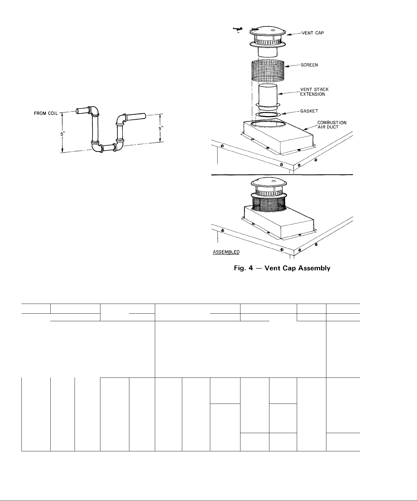
Install a 3-in. trap at drain fitting to ensure
proper drainage. See Fig. 3. Make sure trap outlet
is at least 2 in. lower than unit drain pan connection
to prevent pan from overflowing. Prime trap with
water.
If the installation requires draining condensate
water away from the unit, connect a drain tube
using a minimum of 7/8-in. OD copper tubing.
3/
no
at
ru
ro
on
W
aw
FRC
VI
du
CO
lo(
St£
tO|
bl(
MODEL 48
SERIES 320 320
DIMENSIONS |ft-in.)
FIELD-SUPPLIED FILTER
SIZE (sq. in.)*
Standard Disposable Type
Cleanable- or
High-Capacity Type
OPERATING WT (lb)
SHIPPING WT (lb)
HEATING INPUTS (Btuh)
COOLING AIRFLOW (Cfm) 600
EXTERNAL STATIC
PRESSURE (in. wg)
A 4-5-578
B
C 3-2D 1 -4
E 1 -4
F
G 0- 11
H
K 0-1-
Min
Max
GL018 GL024
2-6-3/8
1/8
0-7-
1/4
1-0-5/8
3/32
289 396
188 257
320
330 335
40,000
50,000
0 10
^Recommended, field-supplied air filter areas shown are based on either cooling airflow at a velocity of 300 ft per
minute or heating airflow at a temperature of 60 F. depending on whichever value is larger Air filter pressure drop
should not exceed 0 08 in wg for unit to produce rated cooling performance
fWhen Models 48GH024 or GH036 are installed for operation at minimum rated heating input, recommended
minimum air filter area Is the smaller sq in figure shown for each type of filter Larger figures shown are mini-
325
40,000
50,000
825
0 10
GH024 GL030
320
396/433t
257/281t
375 375
385
60,000 40,000
75,000 50,000
825
0 10
320/330
*
1088
0 15
522
339
385
GH030
320/330 320/330
4-5-5/8
3-4-3/8
3-5-1/8
1 -7
1-1 1/4
0-8-7/8
0-10
1-5-5/8
3/8
0-1
522 576
339 374 374 374
375 380
385 390
60,000 60,000
75,000 75,000
1088 ^ 1200
0 15 0 15
GL036
520/530 1 620/630
576 576
380
390
60,000 60,000
75,000
1200 1200
0 15 0 15
Table 1 — Installation
GH036
320/330 520/5
380 475
390 485
100,000
75,000
1 25,000
583/722f
379/469t
1215
0 15
583/72
379/461
100,00
125,00
475
485
1215
0 15
h(
tAI
or
Page 4
3/4-in. galvanized pipe,“ or 7/€-in. plastic pipe. Do
not undersize the tube. Pitch drain tube downward
at a slope of at least 1 in. in every 10 ft of horizontal
run. Be sure to check drain tube for leaks.
Condensate water can be drained directly onto
roof in rooftop installations (where permitted) or
onto a gravel apron in ground-level installations.
When using a gravel apron, make sure it slopes
away from unit.
TO DRAIN
Fig. 3 — Condensate Trap
VENTING — The vent cap and combustion-air
duct assemblies are shipped in either the blower or
control compartment. Remove access doors to
locate assemblies. See Fig. 1 for door locations. Vent
stack extension is shipped either in air hole in unit
top or fastened to back of the control box or in
blower compartment.
CAUTION: Venting system is designed to en
sure proper venting. Vent cap assembly must be
installed as indicated in this section of installa
tion Instructions.
allation Data
036
520/530
583/722t
379/469t
475 420 420
485 430 430
100,000
125,000
1215
0 15 0 15 0 15
672 672 672
437 437
60,000
75,000
1400
GL042
5- 5-5/8
3- 8-5/8
3-10-1/8
2-
0
1- 1 -1/4
0- 8-7/8
0-10
1- 6-1/4
1-10-5/8
0- 1
-3/8
520
60,000
75,000
1400
GH042
... “0^
672 768
437 437
440
450
80,000 80,000
100,000 100,000
1400 1400
0 15
440
450
0 15
GL048
320 520
499 499
535
545
80,000
100,000
1600 1600
0 20
80,000
100,000
768
535
545
0 20
620
768
499
535
545
80,000
100,000
1600
0 20
6- 0-3/8
3- 8-5/8
4- 6-1/8
2- 8
-1/4
1- 1
0- 8-7/8
0-10-1/2
1- 3-1/4
2-0-11/16
-3/8
0- 1
GH048
320
768 768
499 499
555 555
565 565
100,000
125,000
1600 1600
0 20 0 20 0 20 0 20
520
100,000
1 25,000
GL060
320/330 320/330
6- 0-3/8
3- 8-5/8
4- 6-1/8
1- 1-1/4
0- 8-7/8
0-10-1/2
1- 6-1/4
2-0-11/16
0- 1-3/8
951
618
575
585 615
100,000 120,000
1 25,000
1981 1981
150,000
GH060
2- 8
951
618
605
mum recommended filter areas when these units have been field converted for operation at maximum rated
heating input
JAH units have a minimum and maximum AGA-certified rated heating input and are manufactured with burner
orifices for heating operation at minimum rating Units may not be derated below this minimum rating
Page 5
IP
NOTE: Screw holes in vent stack extension and
unit top are positioned to ensure proper orientation
when installed.
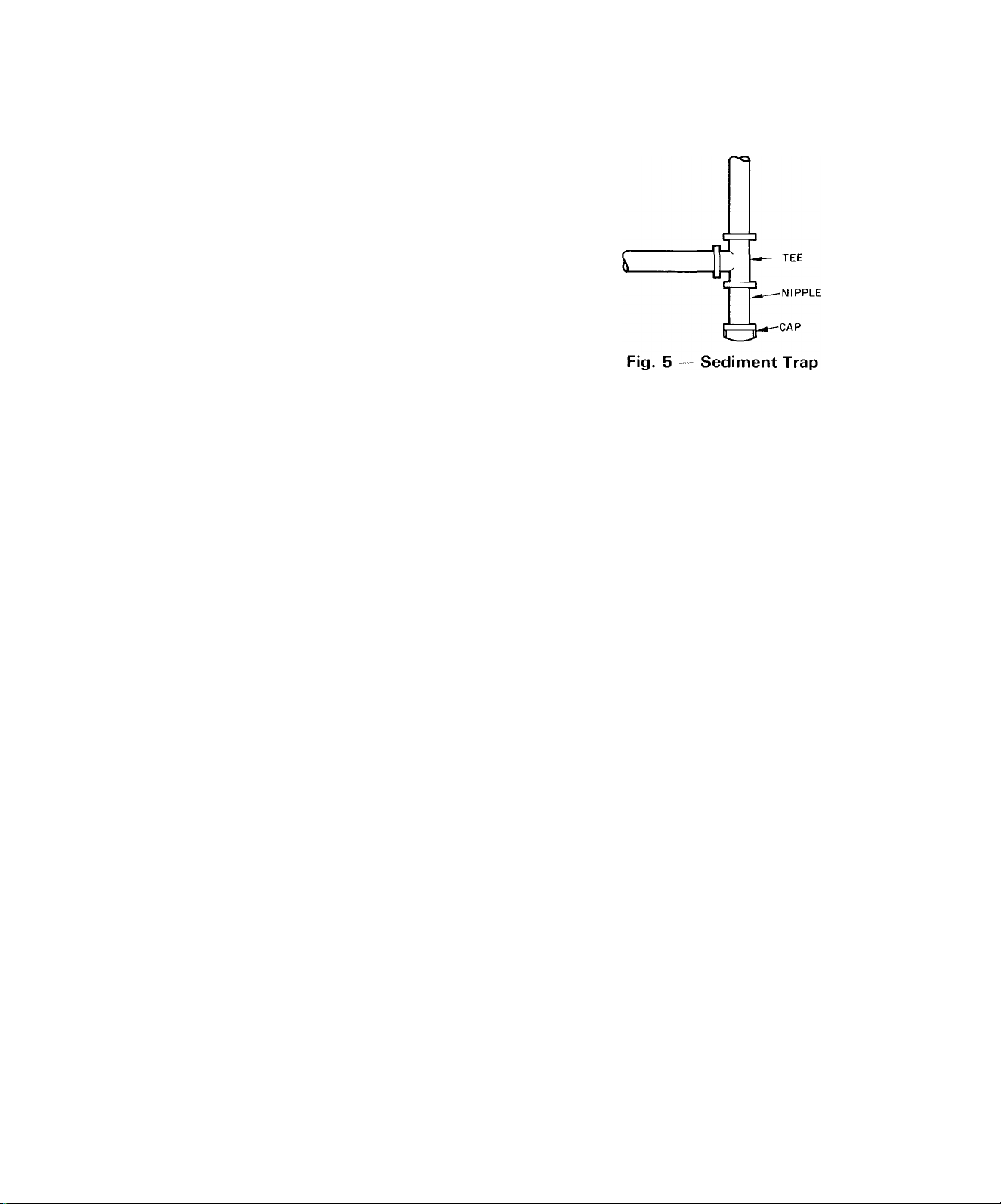
Refer to Fig. 4 and install vent cap as follows:
1. Place combustion-air duct over combustion-air
opening in unit top, and line up screw holes in
duct with holes in top. Secure duct to top using
screws with rubber washers (provided).
2. Place gasket and vent stack extension thru hole
in combustion-air duct, orient screw holes in
base of vent stack extension with holes in unit
top, and secure gasket and vent stack extension
to unit top using screws provided.
3. Form flat wire screen (provided) into circular
shape around protruding lip of combustion-air
duct, and bend wire ends thru holes of screen
mesh to secure screen in place. Make sure that
no sharp edges are left exposed.
4. Place vent cap sleeve inside vent stack extension.
Orient spring clip of vent cap with slot in
extension. Be sure that clip snaps into slot to
secure clip onto extension.
Step 2 — Make Gas Piping Connections — The
gas supply pipe enters unit thru access hole pro
vided. See Fig. 1 for location. The gas connection
to unit is made to the 1/2-in. FPT gas inlet on
gas valve.
Install a separate gas supply line that runs
directly from meter to heating section. Do not use
cast-iron or galvanized pipe. Check local utility for
recommendations concerning existing lines. Choose
a supply pipe that is large enough to keep pressure
loss as low as practical. Never use pipe .smaller than
the 112-in. FPT gas inlet on gas valve.
When installing gas supply line, observe local
codes pertaining to gas pipe installations. Refer to
National Fuel Gas Code ANSI Z223.1-1980 in
absence of local building codes. Adhere to pertinent
recommendations.
1. Avoid low spots in long runs of pipe. Grade all
pipe 1 / 4-in. in every 15 ft to prevent traps. Grade
all horizontal runs downward to risers. Use risers;
to connect to heating section and to meter.
2. Support all piping with appropriate hangers, etc.
Use a minimum of one hanger in every 6 feet. For
pipe sizes larger than 1/2 in., follow recom
mendations of national codes.
3. Apply joint compounds (pipe dope) sparingly
and only to male threads of joint when making
pipe connections. Use only pipe dope that is
resistant to action of liquefied petroleum gases
as specified by local and/ or national codes.
Never use Teflon tape.
4. Install a sediment trap in riser leading to the
heating section. This drip leg functions as a trap
for dirt and condensate. Install trap where con
densate cannot freeze. Install this sediment trap
by connecting a piping tee to riser leading to
heating section so that straight-thru section of
tee is vertical. See Fig. 5. Then, connect capped
nipple into lower end of tee. Extend capped
nipple below level of gas controls.
5. Install an accessible, external, manual shutoff
valve in gas supply pipe within 6 ft of heating
section. Install a 1/8-in. NET plugged tapping
that is accessible for test-gage connection
immediately upstream of gas supply connection
to heating section.
6. Install ground-joint union close to heating
section between gas valve and external manual
shutoff valve.
CAUTION: Unstable operaiion may occur,
particuiarly under htgh-wind conditions^ when
gas valve and manifold assembly are forced out
of piKiltion while connecting improperly routed
rigid gas piping to gas vaive. Use a backup
wrench when making connection to avoid strain
on, or distortion of, gas control piping.
7. Use flexible gas pipe to make connection between
rigid gas piping and gas valve where permitted
by local codes. Flexible pipe ensures proper
alignment between manifold orifices and burner.
WARNING; Never use a match or other open
flame when checking for gas ieaks„
8. Check for gas leaks at all field-insialled and
factory-installed gas lines after all piping connec
tions have been completed. Use soap-and-water
solution (or method specified by local codes
and/or regulations).
Step 3 — Make Duct Connections — Model
48GH/GL has duct flanges on the supply- and
return-air openings on side of unit. See Fig. 1 for
connection sizes and locations.
W'ARNÌNG: The dc-sign and instailation of duct
system must be in accordance with staodardsof
National Fire PTotectson Associatkm for
Instailatiou of nonresidence-type mr condìtioning and ventiiatmg sysieras, NFPA No. 90;
or residence-type, NFP.ÀNo, 90S; and/or local
codes and ordinances.
Page 6

Table 2 — Electrical Data
OPER
MODEL
48
GL018
GL024
GH024
GL030
GH030
GL036
GH036
GL042
GH042
GL048
GH048
GL060
GH060
AWG —American Wire Gage
MCA —Minimum Circuit Ampacity
*Maximum Dual Element Size.
tUse only copper wire for field connections to unit. Wire size is
based on 60 C or 75 C copper conductor at 86 F (30 C) ambient
temperature and ampacity shown in table If other than 60 C or
SERIES
320
320
320
320/330 208-230-1
320/330
320/330
520/530
620/630
320/330
520/530
320
520
320
520
320
520
620
320
520
320/330
320/330 230-1
V-PH
208-230-1
208-230-1
208-230-1
208-230-1
208-230-1
208/230-3
460-3
208-230-1
208/230-3
208-230-1
208/230-3 187 253 21 9
208-230-1 197 253
208/230-3 187 253 21.3
230-1 207 253
208/230-3 187 253
460-3 414 506
230-1
208/230-3 187 253
230-1
VOLTAGE
RANGE
Min Max
197
197
197
197
197
197
187
414 506 9 1
197
187
197 253 26.4
207 253
207 253 43.4
207 253
253
253 160
253 17 3
253 19 3
253
253 25 0
253 18 6
253 24.8
253 19 5
TOTAL
AMPS
11 4
19.1
26 2
30 3
26 6
11.7
29 5
24 6
43 7
MAX BRANCH
CIRCUIT FUSE
SIZE (Amps)*
20 13.8
30
30 20 7 10 112
35 23 4 10 100
35
45 30.0 r 10 77
35 21 9 10 121
15 108
45 29 8
35 22.8 10 116
50 31 8 8
40 25.8
50 31 6 8 117
40 25.2 10
60 36 3 8 107
45 30 8 8 135
20
60 35.5 8 110
45 28 8 10
60 52 3 6
60
75 C copper conductor is used, if ambient temperature is above
86F, or if voltage drop of the wire exceeds 2% of total rated
voltage of the unit, determine wire size from ampacity shown
and National Electrical Code (NEC). Wire lengths shown are
measured one way along wire path between unit and service
panel for minimum voltage drop.
MCA
194 12
23 2
135 14 169
52 6 j 6
MIN
WIRE SIZE
(AWG)t
14
10
14
10 78
10 103
MAX WIRE
LENGTH
(ft)t
67
76
101
218
117
106
92
116
116
Adhere to the following criteria when selecting,
sizing, and installing duct system:
1. Select and size ductwork, supply-air registers
and return-air grilles according to Carrier Sys
tem Design Manual, Part 2. System airflow must
he within range of temperature rise and external
static pressure shown on unit AGA rating plate.
CAUTION; When duci-sj'stem fastening boks
are being drilled into side of Model 4M}HfCL
instead of the unit ductnanges, use extreme care
to avoid puncturing coil or coil tubes.
2. Use a flexible transition between rigid ductwork
and unit to prevent transmission of vibration.
The transition may be screwed or bolted to duct
flanges. Use suitable gaskets to ensure a weather
and airtight seal.
3. Install an external, field-supplied air filter(s)
in return-air ductwork where it is easily accessible
for service. Recommended filter sizes are shown
in Table 1.
4. Size all ductwork for maximum required airflow
(either heating or cooling) for unit being in
stalled. Avoid abrupt duct size increases or
decreases.
5. Adequately insulate and weatherproof all duct
work located outdoors. Insulate ducts passing
thru an unconditioned space, and use a vapor
barrier in accordance with latest issue of
SMACNA and NESCA minimum installation
standards for heating and air conditioning
systems. Secure all ducts to building structure.
6. Flash, weatherproof and vibration-isolate all
openings in building structure in accordance
with local codes and good building practices.
Step 4 — Make Wiring Connections
WARNING: Umt cabinet must have an un~
intemipted. unbroken electrical ground to
minimize the possibility of personal injury'
if an electrical fault should occur. Ibis ground
may consist of electrical wire connected to unit
ground lug in control compartment, or conduit
approved for electrical ground when installed in
accordance with National Electrical Code and
local electrical codes. Do not use gas piping
as an electrical ground. A failure to follow this
warning could result in the installer being liable
for the personal injury' of others.
CAUI ION: A failure lo follow' these precau
tions could result in damage to unit being
installed:
Page 7

1. Make all electrical connections in accordance
with National Electrical Code and local elec
trical codes governing such wiring.
2. Use only copper conductor for connections
between field-supplied electrical disconnect
switch and the unit. Do not use aluminum or
copper-clad aluminum wire.
3. Ensure that high-voltage power to unit is within
operating voltage range indicated on unit rating
plate. On 3-phase units, ensure that phases are
balanced within 2%. Consult the local power
company for correction of improper voltage
and/or phase imbalance.
4. Insulate low-voltage wires for highest voltage
contained within conduit when low-voltage
control wires are run in same conduit as highvoltage wires.
5. Do not damage internal components when
drilling thru any panel to mount electrical
hardware, conduit, etc.
6. Make sure that service conductors used between
the electrical service panel and field-supplied
electrical disconnect switch do not have a current
capacity less than the copper wire specified, and
do not create a total voltage drop in excess of 2%
of rated voltage of the unit.
NOTE: When using aluminum conductor from
electrical service to disconnect switch (where local
codes permit use of aluminum wire), make the
connections in accordance with National Electrical
Code. Prepare all aluminum wire immediately be
fore installation by “brush-scratching” the wire,
then coating the wire with a corrosion inhibitor
(such as Pentrox A). Be sure that entire connection
is completely covered to prevent an electrochemical
reaction that will cause the connection to fail very
quickly. Do not reduce effective size of wire by
cutting off strands to fit wire into a connector.
Always use properly sized connectors.
HIGH-VOLTAGE CONNECTIONS ^ Unit must
have a separate electrical service with a fieldsupplied, waterproof, fused disconnect switch per
NEC mounted at, or within sight from, the unit.
Refer to unit rating plate for maximum fuse size and
minimum circuit amps (ampacity) for wire sizing.
Table 2 shows recommended wire sizes and lengths
based on rating plate data.
The field-supplied disconnect switch box may be
mounted on unit over the high-voltage inlet hole
in control corner panel. See Fig. 1.
WARNING: Label part no, A-74I9ÍB, whickis
shipped loose in bag of parts, must be affixed to
the disconnect switch, box. This iabei states;
“DO NOT DISCONNECT THE ELEC
TRICAL POW'ER TO THIS APPLIANCE
WITHOUT FIRST TURNING OFF THE
GAS SUPPLY ”
1 — Control Transformer
2 — Compressor Contactor
3 — Ground Lug
4 — Dual Run Capacitor
(for compressor and
condenser fan motor)
5 — Low-Voltage Pigtail
Leads
6 — Compressor/Control
Compartment Divider
Panel
7 — Igniter Module
8 — Manual On/Off Knob
9 — Gas Valve Inlet
10 — Pipe Plug —
LP (Propane) unit
pressure switch
mounts here
Fig. 6 — Model 48GL036 — Side View
(Partial) with Access Doors Removed
11 — Pilot Tube
12 - Model 646A-X
Gas Valve
13 — Pressure Tap Pipe Plug
14 — Gas Valve Outlet
15 — Gas Manifold
16 — Gas Burner
17 — Burner Air Shutter
18 — Secondary-Air Shield
19 — Blower Housing
20 — Evaporator Motor
Run Capacitor
21 — Blower/Control
Compartment Divider
Panel
22 — Heating Relay
23 — Cooling Relay
Proceed as follows to complete the high-voltage
connections to unit:
1. Connect ground lead to chassis ground connec
tion when using a separate ground wire.
2. Run high-voltage leads with field-supplied
conduit into unit control box and connect to
contactor. See unit wiring label, and Fig. 6
and 7.
NOTE: On 3-phase units, connect third high-voltage
lead to brown high-voltage pigtail lead. See unit
wiring label and Fig. 7.
SPECIAL PROCEDURES FOR 208-V
OPERATION
WARNING; Make stire that power supply to
«iut k switched OFF before ruakipg any wiring
changes.
Page 8

SINGLE-STAGE HEAT & COOL-MANUAL CHANGEOVER
(p ®
I FIELD
I SPLICE
b ^ ^
V]
I]
-J 3
>•
LOW-VOLTAGE
PIGTAIL LEADS
CONTROL BOX I / | FIELD-SUPPLIED
HIGH-VOLTAGE PIGTAIL LEAD / „"gCONNECT
-------FIELD LOW-VOLTAGE WIRING ■
-------FIELD HIGH-VOLTAGE WIRING ■
NOTE;
For manual changeover applications, use thermostat part no
HH01AD042 with subbase part no HH93AZ042; or thermostat
part no. HH01AD040 with subbase part no HH93AZ040
For automatic changeover, use thermostat part no HH07AT074
with subbase part no HH93AZ096; or thermostat part no
HH10AD041 with subbase part no HH93AZ041
Fig. 7 — High- and Low-Voltage Connections
O
GÛ a:
FIELD-SUPPLIED CONDUIT
CONTACTOR TERMINALS (SEE
UNIT WIRING LABEL)
.POWER
I SUPPLY
HIT I
3-PHASE UNITS ONLY
-FACTORY LOW-VOLTAGE WIRING
-FACTORY HIGH-VOLTAGE WIRING
A grommeted, low-voltage inlet hole is located
in a panel adjacent to control access panel. See
Fig. 1. Run low-voltage leads from thermostat, thru
inlet hole, and to low-voltage flagged pigtail leads
that run thru a hole in bottom of unit control box.
See Fig. 6. Connect thermostat leads to the pigtail
leads as shown in Fig. 7.
HEAT ANTICIPATOR SETTING — Room ther
mostat heat anticipator must be properly adjusted
to ensure proper heating performance. Set heat
anticipator to approximately 0.85 amps. Use an
ammeter to determine exact required setting.
Failure to make a proper heat anticipator adjust
ment will result in improper operation, discomfort
to occupants of conditioned space, and inefficient
energy utilization; however, required setting may be
changed slightly to provide a greater degree of
comfort for a particular installation.
START-UP
Unit Preparation
WARNiNG/DANGER: Failure to observe ifee
foliowirig warnbigs could result m serious
personal injury;
When operating Models 48GL018 thru042 single
phase units or Models 48GH036 thru 048 threephase units at 208 volts, disconnect orange
transformer-primary lead from contactor. See unit
wiring label and Fig. 7. Remove tape and cover
from terminal on the end of red transformer
primary lead. Save cover. Connect red lead to
contactor terminal from which orange lead was
disconnected.
Using cover removed from red lead, insulate
loose terminal on orange lead. Wrap cover with elec
trical tape so that metal terminal cannot be seen.
NOTE: For some units, the factory-wired blowermotor speed connections may require changing for
208-volt operation to ensure adequate airflow at the
rated external static pressure. See unit wiring label.
Insulate all unused motor leads following same
procedures described for transformer leads.
LOW-VOLTAGE CONNECTIONS — Use a suit
able room thermostat as specified on unit wiring
label.
Locate room thermostat on an inside wall in space
to be conditioned where it will not be subjected to
either a cooling or heating source, or direct exposure
to sunlight. Mount thermostat 4 to 5 ft above floor.
Use No. 18 AWG color-coded, insulated (35 C
minimum) wires to make low-voltage connections
between thermostat and unit. If thermostat is
located more than 100 ft from unit (as measured
along the low-voltage wires), use No. 16 AWG
color-coded, insulated (35 C minimum) wires.
1. Follow recognized safety practices and wear
protective goggles when checking or servicing
refrigerant system.
2. Do not operate compressor or provide any
electric power to unit unless compressor
terminal cover is in place and secured.
3. Do not remove compressor terminal cover until
all electrical sources have been disconnected.
4. Relieve all pressure from system before touching
or disturbing anything inside terminal box if a
refrigerant leak is suspected around compressor
terminals.
5. Do not use a torch to remove any component.
System contains oil and refrigerant under
pressure. To remove a component, wear protec
tive goggles and proceed as follows:
a. Shut off gas supply and then electrical
power to unit.
b. Relieve all pressure from system.
c. Cut component connecting tubing with
tubing cutter and remove component from
unit.
d. Carefully unsweat remaining tubing stubs
when necessary. Oil can ignite when exposed
to torch flame.
PRE-START-UP PROCEDURES ^ Proceed as
follows to inspect and prepare unit for initial
start-up:
1. Remove all access panels.
2. Read and follow instructions on all WARNING,
CAUTION, and INFORMATION labels
attached to or shipped with the unit, such as
blower rotation labels, etc.
Page 9

3. Make following inspections;
a. Inspect for shipping and handling damages
such as broken lines, loose parts, disconnected
wires, etc.
b. Inspect for oil at all refrigerant tubing connec
tions and on unit base. Detecting oil generally
indicates a refrigerant leak. Leak-test all
refrigerant tubing connections using elec
tronic leak detector, halide torch, or liquid-
soap solution. If refrigerant leak is detected,
see REFRIGERANT LEAKS in next part
of this section.
c. Inspect all field- and factory-wiring connec
tions. Be sure that connections are completed
and tight.
d. Inspect coil fins. If damaged during shipping
and handling, carefully straighten fins with
a fin comb.
Do ivo=t purge ^ sjippiy iisio
coa&ustioijL Do aot o&e a itnaidt or
other opesi ilajne £o t^edc for gas leaks,
4. Verify the following conditions:
a. Make sure that gas supply has been purged,
and that all gas piping has been checked for
leaks.
b. Make sure that outdoor fan blade is correctly
positioned in fan orifice. Blades should clear
fan motor by exactly 114 inch.
c. Make sure that air filter(s) is in place.
d. Make sure that condensate drain pan is filled
with water to ensure proper drainage.
e. Make sure that all tools and miscellaneous
loose parts have been removed.
5. Replace all access panels. Unit is now ready for
initial start-up.
REFRIGERANT LEAKS — Proceed as follows to
repair a refrigerant leak and to charge the unit:
WARl^’iNG: Never attempt to repair a soldered
connection, wbiie the refrigeraiii system is under
psressure. Severe bodily injury may result.
Always wear proieaive goggles when servicing
the Tefrigerant system,
1. Locate leak and ensure that refrigerant system
pressure has been relieved.
2. Repair leak following accepted practices.
NOTE: Install a filter drier whenever system has
been opened for repair.
3. Add a small charge of R-22 refrigerant vapor to
system and leak-test unit.
4. Evacuate refrigerant system if additional leaks
are not found.
5. Charge unit with R-22 refrigerant, using a
volumetric-charging cylinder such as Dial-aCharge or accurate seale. Refer to unit rating
plate for required charge. Be sure to add extra
refrigerant to compensate for internal volume of
filter drier.
NOTE: See Cooling Section Start-Up and Adjust
ments — CHECKING AND ADJUSTING RE
FRIGERANT CHARGE.
Heating Section Start-Up and Adjustments
CAUTION; Complete required procedures
given in Unit Pn^ratioii section before starttng
unit.
Do not jumper any safety devices when operating
unit.
Ensure that burner orifices are properly aligned.
Unstable operation may occur when burner orifices
in manifold are misaligned. To ensure eorreet
burner orifice alignment, check orifice angle with a
maehinist’s protractor or other suitable device. The
orifice angle must be from horizontal to 3 degrees
down, as measured from unit base.
Follow instructions on heating section operation
label (located in unit near the gas valve) to start
heating section.
CHECKING HEATING CONTROL OPERA
TION — Start and check unit for proper heating
control operation as follows;
Place room thermostat selector switch in HEAT
position and fan switch in AUTO, position. Set
heating temperature control of thermostat above
room temperature. Observe that after built-in time
delays, pilot automatically lights, burners light, and
blower motor starts. Observe that burners and pilot
go out, and that after a built-in delay blower motor
stops when heating eontrol setting of thermostat is
satisfied.
GAS INPUT — Unit rating plate indicates 2 AGAcertified gas inputs. When shipped from factory,
manifold has natural-gas burner orifices that deliver
minimum rated gas input. Optional field-installed
burner orifices are required to provide optional
maximum rated gas input. See Table 3.
When unit is being installed for operation at the
optional input, proceed as follows to install fieldsupplied burner orifices:
1. Remove burner shield and burners.
2. Remove factory-supplied burner orifices from
manifold and replace with field-supplied orifices.
3. Replace burners and burner shield.
4. Mark appropriate changes on unit rating plate.
CAUTION: These units are designed to con
sume rated gas inputs using fixed orífices at
specified manifold pressures as .shown in
Table 3. Do not redtill orifices under any
circumstances.
Page 10
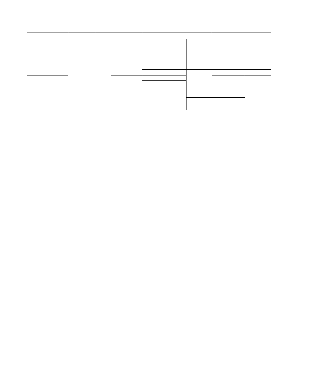
Table 3 — Rated Gas Inputs (Btuh) for Various
Burner Orifices at Indicated Manifold Pressures*
Nat
3 5
MANIFOLD
P
KfcSSUHt
(in. wg)
LP (Propane)
105
105
MODEL
48
GL018,024,030
GH024.030
GL036,042
GH042; GL048
GH036.048
GL060
GH060
*Data in this table is based on altitudes from sea level up to either
7000 ft above sea level at the minimum rated input, or 2000 ft
above sea level at the maximum rated input For higher altitudes,
follow the recommendations of national and local codes
fGas inputs for natural gas are based on a heating value of
1050 Btu per cu ft with a specific gravity of 0 65 at the factory-set
NUMBER
OF
ORIFICES
2 3 5
3 3 5 105
4 3 5 105
5
6 3 5 10 5
The minimum and maximum rated gas inputs
shown in Table 3 are for altitudes from sea level up
to either 7000 ft above sea level at minimum input,
or 2000 ft above sea level at maximum input. These
inputs are based on natural gas with a heating value
of 1050 Btu per cubic foot at 0.65 specific gravity,
or LP (propane) gas with a heating value of 2500 Btu
per cubic foot at 1.5 specific gravity. For elevations
above either 7000 ft at minimum input or 2000 ft
at maximum input, reduce ratings 4% of maximum
input for each 1000 ft above sea level. When gas
supply being used has a different heating value or
specific gravity, refer to Carrier training and
application materials, national and local codes, or
contact your Carrier dealer to determine required
orifice size.
ADJUSTING GAS INPUT
CAUTION; WbsD adjusting ihe gas input, do
not change manifold pressure more than
0.3 in. wg above or below setting shown in
'Fable 3. if larger adjustments are required,
change burner orifices foUowditg recommenda
tions of national and local codes.
Gas input to unit is adjusted by changing mani
fold pressure. Use REG ADJ screw on gas valve to
change manifold pressure as follows:
To increase input: Turn screw clockwise.
To decrease input: Turn screw counterclockwise.
Gas input can be determined and adjusted by
using one of the following 2 recommended methods:
1. Measuring gas flow at meter.
2. Measuring manifold pressure.
NATURAL GAS
Orifice
Part No.
LH32DB-205t (Min)
LH32DB-207 (Max)
LH32DB-205t (Min)
LH32DB-207 (Max)
LH32DB-200t (Min) 80,000 LH32DB-201
LH32DB-096 (Max) 100,000
LH32DB-200t (Min) 100,000
LH32DB-096 (Max) 125,000
LH32DB-200I (Min)
LH32DB-096 (Max)
manifold pressure of 3 5 in wg Gas inputs for LP (propane) gas
are based on a heating value of 2500 Btu per cu ft with a specific
gravity of 1 5 at a manifold pressure of 10 5 in wg
iThese natural gas burner orifices are the factory-supplied orifices.
All other natural gas orifices shown are optional field-supplied
orifices
Heating
Input
(Btuh)t
40.000
50.000
60,000 LH32DB-201
75,000 LH32DB-060
120,000
150,000
LP (Propane) GAS
Orifice
Part No
LH32DB-201
LH32Db'-060”" '
LH32DB-060
LH32DB-201 100,000
LH32DB-060 125,000
LH32DB-201
LH32DB-060
Measuring Gas Flow at Meter
NOTE: All other gas appliances that use the same
meter must be turned off when the gas flow is
measured at the meter.
Proceed as follows to measure gas flow at meter
to determine gas input:
a. Determine number of seconds for gas meter test
dial to make one revolution.
b. Divide number of seconds in step a into 3600
(number of seconds in an hour).
c. Multiply result of step h by number of cu ft
shown for one revolution of test dial to obtain
cu ft of gas flow per hour.
d. Multiply result from .v/cp c by Btuh heating value
of gas to obtain total measured input in Btuh.
Compare this value with input shown in Table 3.
NOTE: Consult local gas supplier if heating value of
gas is not known.
Example: Assume that size of the test dial is 1 cu ft,
one revolution takes 30 seconds, and heating value
of gas is 1050 Btuh per cubic foot, then proceed
as follows:
a. 30 seconds to complete one revolution.
b. 30 divided into 3600 equals 120.
c. 120 times 1 equals 120 cu ft of gas flow per hour.
d. 120 times 1050 equals 126,000 Btuh input.
If desired gas input is 125,000 Btuh, only a minor
change in manifold pressure is required.
Measuring Manifold Pressure — When heating
value of gas is significantly more or less than design
value, or slight manifold pressure changes are
necessary for other reasons, manifold pressure
may be changed to adjust gas input. Use a water
manometer to measure manifold pressure. If a
spring manometer is used, make sure manometer
is calibrated.
Heating
Input
(Btuh)t
40.000
50.000
60,000
75,000
80,000
100,000
120,000
150,000
#
10
Page 11
Proceed as follows to measure and change
manifold pressure:
a. Turn off gas to unit.
b. Remove pipe plug on gas valve outlet identified
as PRESS TAP, then connect manometer at
this point.
c. Turn on gas to unit and start heating section.
d. Measure and change manifold pressure with all
burners fired to obtain desired gas input.
e. Turn off gas to unit, remove manometer from
gas valve, and replace pipe plug.
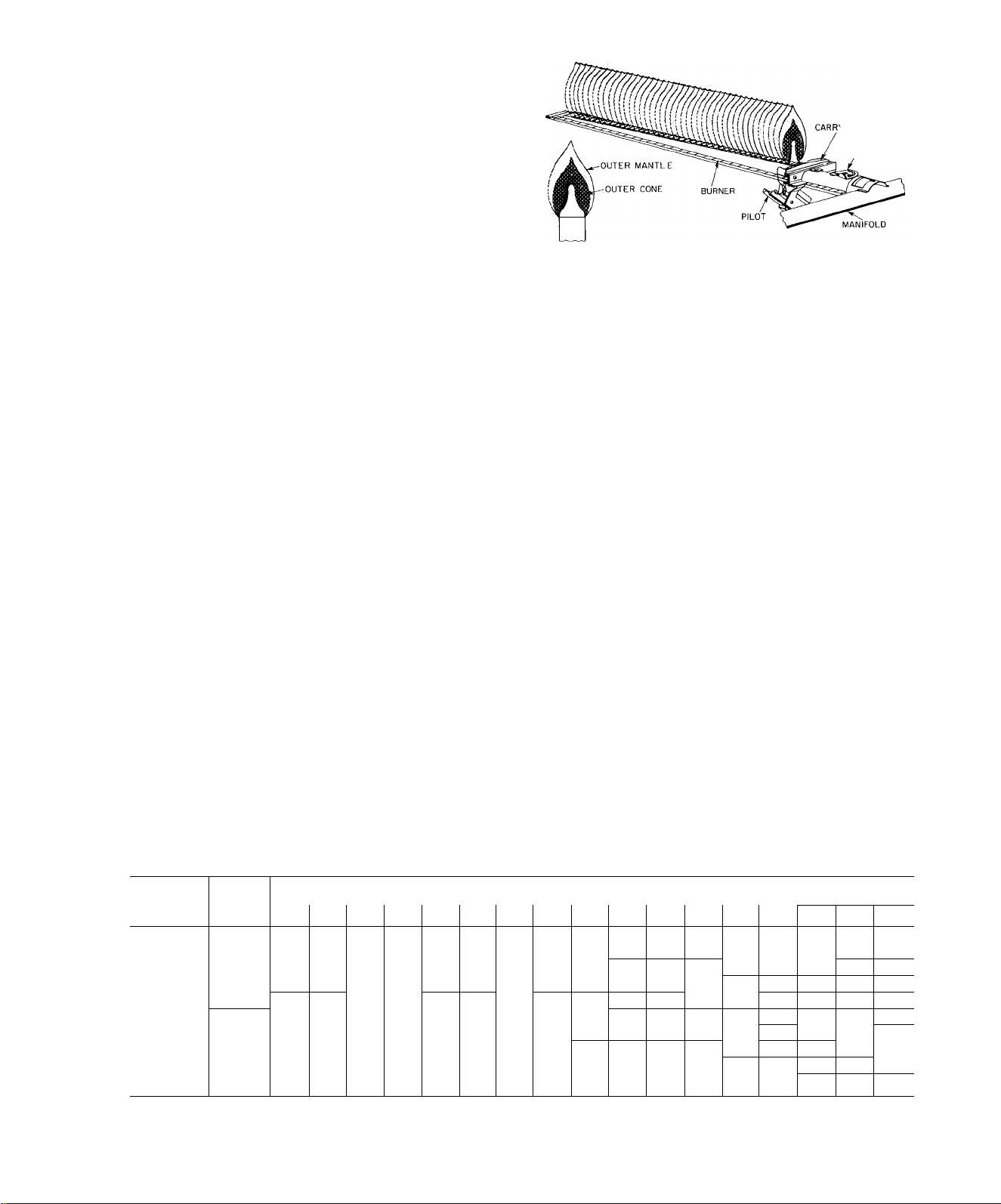
Fig. 8 — Burner Flames
AIR
SHUTTER
#
ADJUSTING BURNER AIR SHUTTERS —
After burners have operated at full input for at least
10 minutes, adjust primary air to each burner to
ensure optimum heating performance. Make these
adjustments when unit is being installed and during
routine maintenance inspections at beginning of
each heating season. Be sure that each burner is
clean and free of deposits before adjusting primary
air.
The primary air to each burner is regulated by
burner air shutter on each burner. See Eig. 8 for
location of burner air shutter. With all burners
operating, adjust primary air to each burner as
follows:
1. Eoosen locking screw that secures air shutter
in place on burner, then partially close air shutter
until a slight yellow tip appears on top of burner
flames.
2. Open air shutter very slowly until yellow tip just
disappears, then secure air shutter in place with
locking screw.
3. Repeat steps 1 and 2 for each burner.
After air shutter adjustments have been com
pleted, observe that flames on each burner are light
blue and “soft” in appearance, and that flames are
same height along the entire length of each burner.
See Fig. 8.
BLOWER HEAT-RELAY OPERATION —
Heating relay (see Fig. 6 and unit wiring diagram) is
located in control box and adjusts to permit either
longer or shorter OFF cycles. The ON cycle auto
matically adjusts as OFF cycle changes. Adjusting
lever on relay is factory-set at center position to
provide optimum performance for most installa
tions. On unusual installations, or where line voltage
is considerably above or below rated voltage, length
of time blower remains on may require increasing or
decreasing. To increase blower operation time,
move adjusting lever toward right-hand position.
In this position, control makes contact sooner and
takes maximum time to break contact. To decrease
blower operation time, move lever toward left-
hand position.
AIRFLOW AND TEMPERATURE RISE —
Temperature rise is temperature difference between
air in return duct and air in discharge duct at unit.
Heating section of each size of unit is designed and
approved for heating operation within temperature
rise range stamped on unit rating plate.
Table 4 shows the approved temperature rise
range for each unit and air delivery (cfm) at various
temperature rises for both AGA-certified gas
input ratings. Heating operation airflow must
produce a temperature rise that falls within
approved range.
Table 4 — Air Delivery (Cfm) at Indicated Temperature
Rise and Rated Heating Input
MODEL
48
GL018,024,
030
GH024.030
GL036.O42
GH042
GL048
GH036.048
GL06O
GH060
“These inputs are the minimum rated inputs using factory-installed burner
orifices Higher inputs shown for each size are the maximum rated inputs
using field-installed, optional burner orifices that are indicated on unit
rating plate
HEATING
INPUT
(Btuh)
40,000* 794
50,000 1032 963
60,000*
75,000 1548
80,000*
100,000 2063
100,000*
1 25,000 2579
120,000*
150,000
35
1190
1587 1481
1984
2381
3095
37 5
741 694
1111 1042 980 926 877 833 794
1444 1354 1275 1204 1140
1926
1852 1736
2407 2257
2222
2889
42 5 45
40
654 617
903 850 802 760 722
1389 1307 1235 1170 nil
1806 1699
1634 1543 1462
2124 2006 1901
1961 1852 1754
2083
2549 2407
2708
47,5 50 52 5 55 57 5
585
1605 1520
2281 2167 2063 1970
TEMPERATURE RISE (F)
62 5
60
556 529 505 483 463 444
688 657
758 725 694 667 641
1083 1032 985 942
1058 1010 966 926
1444
1376 1313 1256 1204
1389 1323 1263 1208 1157 1111
1806 1720 1641 1570 1505 1444 1389 1337 1290 1245
1667 1587
1515
NOTE: Models 48GL018,024,036; 48GH024,030 have an approved tem
perature rise range of 35 to 75 F All other units have an approved tempera
ture rise range of 45 to 75 F
602
628
903 867 833 802
1449 1389
1884 1806
578 556 535 516 498 481
889
1156
1333
1733 1667 1605
67 5
65
412 397
427
617 595 575 556
855
823
1111
1070
1068 1029
1282
1235 1190 1149
70 72 5 75
383 370
774
747 722
794
766
1032 996
992
958
1494 1444
1548
11
741
963
926
1204
1111
Page 12

Refer to Cooling Section Start-Up and Adjust
ments — INDOOR AIRFLOW AND AIRFLOW
ADJUSTMENTS of these instructions to adjust
heating airflow when required.
LIMIT AND PRESSURE SWITCHES — Furnaee
limit switch (see Fig. 9) closes gas valve if leaving-air
temperature exceeds 175 F.
Normally closed limit switch completes control
circuit thru pigtail lead W to gas valve. See Fig. 9.
Should the leaving-air temperature rise to 175 F,
switch opens and W control circuit breaks. Any
interruption in W control circuit instantly closes
gas valve and stops gas flow to burners and pilot.
The indoor fan motor continues to run until timedelay sequence of time delay relay (heating) is
completed.
When air temperature at limit switch drops to the
low-temperature setting of limit switch, switch
closes and completes W control circuit. Electricspark ignition system cycles and unit returns to
normal heating operation.
Pressure switch (Fig. 9) is required only when
unit operates on LP (propane) gas.
Cooling Section Start-Up and Adjustments
CAUTION: CoTsplete required procedures
given iu Urrit Preparation section before start
ing UTSit,
£)o Bot jtintper any safety devices when oper-
atijig unit.
Do aot operate compressor when outdoor
temperature is beiow 55 F.
To prevent rapid cycling of compressor.
Time Guard ii circuit is supplied as standard
eqaipmeut.
CHECKING COOLING CONTROL OPERA
TION — Start and check unit for proper cooling
control operation as follows:
1. Place room thermostat selector switch in OFF
position. Observe that blower motor starts when
fan switch is placed in ON position and shuts
off when fan switch is placed in AUTO,
position.
2. Place selector switch in COOL position and fan
switch in AUTO, position. Set cooling control
below room temperature. Observe that com
pressor, condenser fan, and evaporator blower
motors start. Observe that cooling cycle shuts
down when control setting is satisfied.
3. When using an automatic changeover room
thermostat, place both selector and fan switches
in AUTO, position. Observe that unit operates
in heating mode when temperature control is
set to call for heating (above room temperature)
and operates in cooling mode when temperature
control is set to call for cooling (below room
temperature).
CHECKING AND ADJUSTING REFRIG
ERANT CHARGE — Refrigerant system is fully
charged with R-22 refrigerant, tested, and factory
sealed. For most applications, factory charge is the
correct amount for best performance.
NOTE: Adjustment of refrigerant charge is not
required unless unit is suspected of not having
proper R-22 charge. For all applications, correct
R-22 charge for best performance is charge that
results in a suction gas superheat of 5 F at com
pressor inlet when unit is operating at ARI rating
conditions of 95 F db outdoor and 80 F db/67 F wb
indoor.
An operating pressure/ temperature tag is
fastened inside the compressor compartment. When
evaluating the refrigerant charge by checking oper
ating pressures and temperatures, use tag to ap
proximate charge if ARI rating conditions cannot
be obtained. See Table 5. This method of evaluating
ensures that an optimum refrigerant charge is in
system when system conditions and components are
normal; however, adjusting refrigerant charge does
not solve or fix system abnormalities.
Amount of refrigerant charge affects how effi
ciently and economically unit operates. An over
charged or undercharged unit leads to diminished
cooling efficiency, high operating costs and the
possibility of premature compressor failure.
CAUTION: When evalnatisg EeMgerant
charge, an indicated adjustment to specified
factory charge must always he muhnsai. If a
substantial adjustment is indicated, an ab
normal condltiou exists sotmewhere in cooUng
sy'stem, such as insufficient airflow across either
coil or both coils.
NOTE: For best results, evaluate refrigerant charge
when outdoor temperature is 65 F or higher.
Proceed as follows to evaluate system perform
ance and refrigerant charge:
1. Remove caps from low- and high-pressure
service fittings.
2. Attach low- and high-side pressure gage hoses
to low- and high-pressure service fittings,
respectively. Hoses must have valve core de
pressors. Gages must be calibrated for accuracy.
3. Set room thermostat below room temperature to
start cooling operation. Allow unit to operate
until conditions stabilize and pressures level out.
4. Determine and record these conditions:
a. Low- and high-side pressures.
b. Dry-bulb temperature of inlet air at outdoor
condenser coil.
c. Wet-bulb temperature of inlet air at indoor
evaporator coil.
d. Suction gas temperature at compressor inlet if
unit is operating at ARI standard rating con
ditions indicated on operation pressure/
temperature tag.
12
Page 13
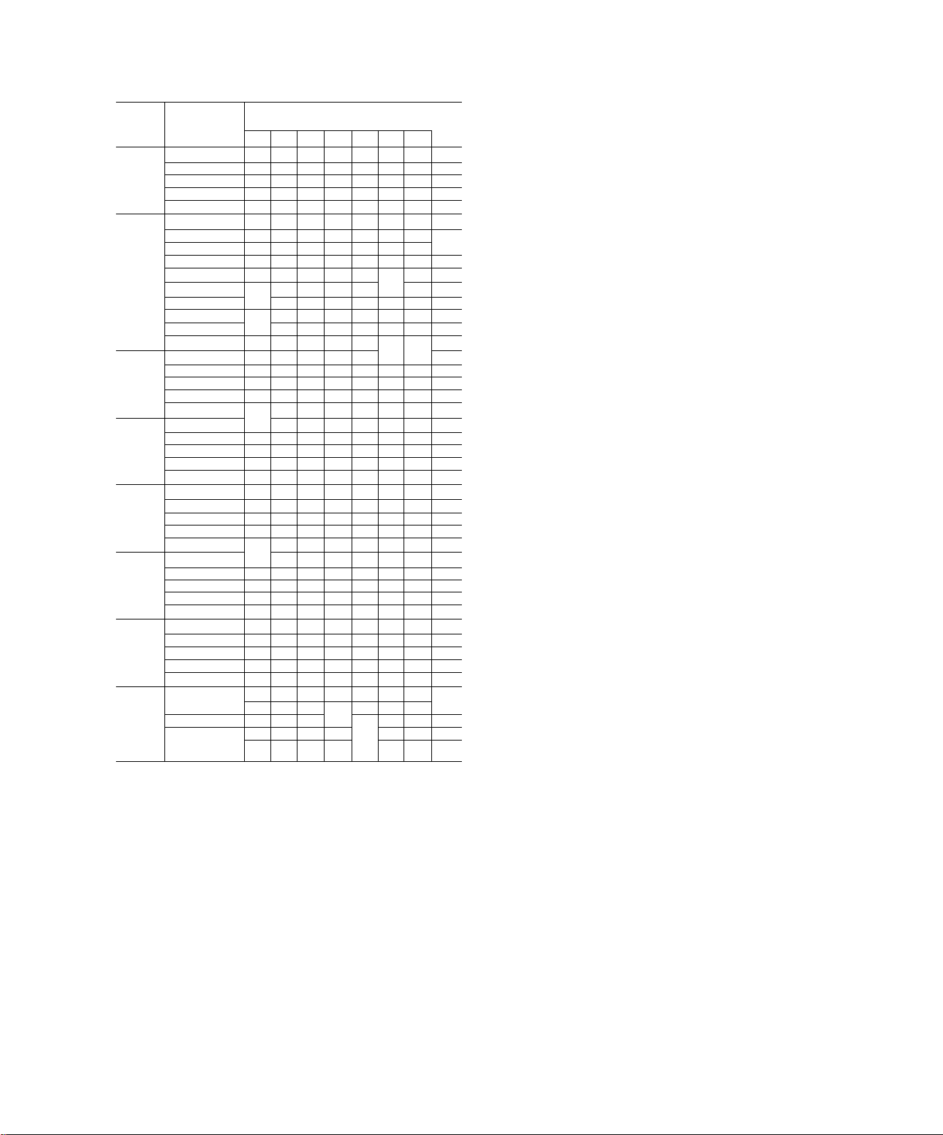
Table 5 — Refrigerant (R-22) Charge
Check Charts*
48
GL036
GH060
EVAPORATOR
AIR INLET
WET BULB (F)
55
60 143
70
75
55 157 170
60
65 160 173 187
70
75 163 177 191 205 220 235 251 267
55
60
70 153 169
75
55 163 178 193 208 220 235 247
60 165 180
65
70 169
75
55 172 186 200 214 229 244
60 175 190 204
65
70
75 185 200 215 230 245 260 275 290
55 168
60
65
70 175 191 206 221 237
75
55
60 180
65 183 198
70
75 189
55
60
65
70
75
55
60
65 177 194
70 179 196 213 231 248 266 284 301
75
CONDENSER AIR INLET TEMP (F)
65
70 75 80 85
138 156 174 192 211 229
161 178 196 213
148 165 182
153 169 186
174
158
158
161
148
150
155
167 182 197 212 226 241
171 186 201 216 232 247
178
182 197 212
171 185 199
173 188
176 193 209
177 192
186 201 217 233
171
176
181
185
188
173
175
181 198
190 206
183 197 210 223 238
172 185
175 189 202 217 232 247
163 178 193 208 224
165 181 195
184
186 202
171
195
184
199
193 208 222 238 252
182 196
203 217 233
208
195 211
214
204 220 236 255
182 193
188 200 211
193 206 218 232 245
197
210 223 238 252 267 282
215
201
190 204
192 207
210 227
216
216 233 251 268
199
202 219
222
212
198
214
200
211
199 215 230 245 261
217 232 247 263
210 223 238 251 266
214
229
233 248 264
218
241
226
223
209
213 228 243 259 276
242
225
224
239 253 269 285
227 243 258 274 290
247
230
251 268
204
216 228 242 257
224
228 243 258 274 291
236
219
223 240
244
252 271
235
90 95
231
236 252 269
238
225 240 255
228 243 259
226 241 256
244
256 271 286
238 253 268
248 266 283
253
258 275 292
263 279 295
273 289 305
237 251 265
251 266 280
256
261 278 294
100
247 265
266
249
254 270
253
262
254
239
262
255 270
274
259
276
263
274
260
278
282
268
271
288
284
300
274
258
272 287
290 308
MODEL
GL018 65
GL024
GH024 65 151 167 182 197 213 228 243 258
GL030,
GH030
GH036
GL042,
GH042
GL048.
GH048
GL060.
*Table shows recommended discharge pressures at compressor (psig)
5. Evaluate system performance and refrigerant
charge by comparing recorded readings with
operating pressure/temperature tag.
6. Make slight adjustment to refrigerant charge
when necessary.
NOTE: If problem causing inaccurate readings is
a refrigerant leak, see Unit Preparation — RE
FRIGERANT LEAKS.
INDOOR AIRFLOW AND AIRFLOW AD
JUSTMENTS — Models 48GH/GL have directdrive blower motors. All motors are factory
connected to deliver proper heating and cooling
airflows at normal external static pressures (except
for some 208-v applications).
CAUTiON; doling opersaion, recota-
fscfsticd airflow is 35& to 450 cfm per 12^^
Bivtk of xaied ooogng capacity. For
operatioo, airflow iami ptodwce a teaaijoraaésffo
rise that faOs withia ras^e staw«^ ojì. Wt ,
raimg plate.
Table 4 shows heating airflow at various tempera
ture rises. Table 6 shows both heating and cooling
airflows at various external static pressures. Refer
to these tables to determine airflow for system being
installed. See Tables 1 and 6 for cooling airflow.
NOTE: Be sure that all supply- and return-air
grilles are open, free from obstructions and
adjusted properly.
WARNING; Dii<coaneci cìtìctricai power îo
OHil perore c&aoging my teas cotmìctìo-m ot
......................................................
■ 'iliiill
NOTE: When operating the 208/230-volt, 3-phase
version of size 48GH048 at 208 volts, change lead
connections of the blower motor as indicated on
unit wiring label to insure a proper airflow.
The heating and/or cooling airflow of 208/230-v
motors can be changed by changing lead connec
tions of blower motor. Motor leads are color-coded
as follows:
black - high speed
blue - medium speed
red - low speed
NOTE: Some blower motors do not have lead for
medium speed. Factory connections and available
optional connections are shown in Table 6.
For all units, motor lead connected to time delay
relay (heating) determines heating speed and
resulting airflow; and motor lead connected to
indoor fan relay (cooling) determines cooling speed
and resulting airflow. See unit wiring label.
To change heating and/or cooling speed, connect
appropriate color-coded lead to appropriate relay.
Be sure to properly insulate any unused motor lead.
See Typical Wiring SPECIAL PROCEDURES
FOR 208-V OPERATION for proper procedures to
insulate an unused electrical lead.
When installing a 208- or 230-v unit that is
factory connected for heating and cooling speeds
that are not the same, and same speed for both
heating and cooling is required for a particular
application, connect appropriate color-coded lead
to terminal 2 of indoor fan relay (cooling) and
connect a field-supplied jumper between time delay
relay (heating) and terminal 2 of indoor fan
relay (cooling). Be sure to properly insulate unused
motor lead(s).
...........
■ "
13
Page 14
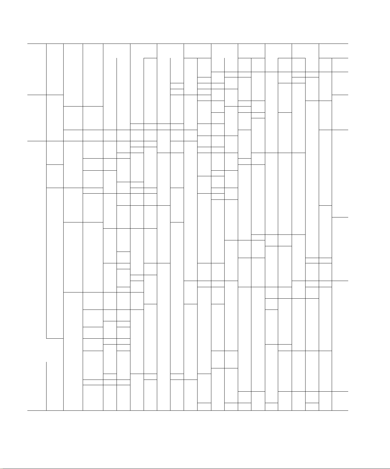
Table 6 — Air Delivery (Cfm) at Indicated External
Static Pressure and Voltage*
MODEL
48
SERIES
GL018
320
GL024
320
GH024
320
GL030
320/
330
GH030
320/
330 23 0-1
GL036
320/
330
520/
530
620/
630
GH036
320/
330
520/
530
GL042
320
520
1
1
GH042
320
520
UNIT
VOLTS/
PHASE
(60-Hz)
208-
230-1
208-
230-1
208-
230-1
208-
230-1
208-
208-
230-1
208/
230-3
460-3
208-
230-1
208/
230-3
208230-1
208/
¡ 230-3
208-
230-1
208/
230-3
BLO WER
MOTOR
SPE ED
Low
High
Low
High
Low
High
Low
High
Low
High
Low
High
Low
High
Low
High
Low
High
Low
High
Low
High
Low
High
High
Low
High
APPLIC A-
TIONt
Hea t 735 805
Coo li 725
Hea tt 790 870
Coo l
Hea ti
Coo l 87 0 9 20
Hea t 98 0 1030
Coo li 945 995
Hea t 960 1030
Coo lt
Hea tJ 112 5 1160
Coo l 1085 1 120
Hea tJ 700 850
Coo l
Hea t 1325 1 370
Coo li 1270 1310
^ Heatf 1125 1175
Coo li 1095 1140
Hea t 1225 1 260
Coo l 1190 1 220
Hea tJ 950 1250
Coo l 945 1225
Hea t 1570 1 610
Coo li 1505 1540
Hea ti
Coo l
Hea t 1525 1620
Coo li 1495 1580
Hea ti
Coo l
Hea t
Coo li
Hea t 1280 1 510
Coo li 1270 1485
Hea ti 1825 1905
Coo l Ì76Ò~^ 182 5
Hea t 1275 1 505
Coo li 1270 1490
Hea t 1625 18 45
Coo l
Hea ti 2035 2130
Coo l 1960 20 45
Hea ti 855 1035
Coo l 850 103 0
Hea t 1700 1 770
Coo li 1635 1705
Hea ti 970 1 190
Coo l 965 118 5
Hea t
Coo li
Hea ti
Coo l 1390 153 5
Hea t 1705 1 770
Coo li 1650 1705
Hea ti 1405
Coo l 1400 1 640
Hea t 1725
Coo li 1705
0 0
230 V
ür
208 V
460 V
775
895
935
1000
690 835
1165 1365
1160 135 0
1165
—
1160
1525
—
1495
-
1605
1800
2040
2145
1960"
'”2056
1410 158 0
1650
1935
1875
0 1
230 V
or
208 V
460 V
700 765 660 725 615
790
690 750 650 710 605
750 825 705 780 660
850 735 810 6 90 765 6 45
950 850
905 8 00 855
825 875
930 975 875 920 820
895 945 845 895 795
925
990
900 965 870 935 835
1075
1115
1040
1075
680 820 655 795
670 810 650 785 630
1270
1310 121 0
1220
1250
1070 1115 1015 1050 955
1035
1080 990
1165
1200
1135
1165 1075
945 1205 940 1160 930
940 1180 935 1 135 9 25
1500 1540 1425 1470 135 5
1440 1480 1375 1420 13 10
1150 1345 1 140
1145 1330 1 130 1 305 1115
1490 1580 14 50 1540 1 415
1460 1540 14 20 1500 Ì385
1150
1145
1490
1460
-
1260 1480 12 40 1445 1 215
1250 1450
1765 1845 1700 1775 1630
1695 1770 16 25
1270 1490 12 60 1 470 1240
1260 1470 12 50 1 450 1230
1605
1805 1575 1760 1540
1575 1755 1545 1705 1505
1980 207 0 1 920 2010 1855
1905 1985 1 840 1925 177 5
845 1025 835 1010 820
840
1020 830
1635 1705 1565 1635 14^6
1570 1635 15 05 1560 14 40
965
1180 960 1175 950
960
1175 955 1165 945
1980
2080
1900
1985
1385
1530 1355 1475 131 5
1365
1485 133 0 14 35 1280
1650 1710 15 90 1 645
1590
1645 153 0 15 80 1465
1400 1635 139 5 1 610 1385
1395 1620 13 85 1590
1710 1885 168 5 1835
1685 1825 1655 1775
0 2
230 V
or
208 V
780 825 730
890 955 855
1030
995
1160
1105
-
-
-
-
1225 1410 1200
1915
1840
208 V
460 V
750
1065 980
1030 9 50
635
1245
1150
1190 1100
1025 940
1040
1140
Ilio
1015
1320 1125
1140
1130
1450
1420
1550
1695
1005
815
2010
1850
1920
1775
1525 15 75 1450 150 0 1365
1370 155 5 1345 1 510 1310
1655 1 780
1615 17 25
EXT ERNAL
0 3
-
-
-
-
STA TIC PRES S
230 V
or
208 V
460 V
675
565 625 520
660
555 610
735 610
720 595 670 545 620
800
700 745 645
775
680
865 765 810 695 750
840 740 790 680 735
920 815 880 780 840
890 800
1015 930 965 880 9 15
980 900 935 855 885~^
765 610 735 585 705
755 605 725 58 0 695^^
1180 1090 1 110 1020
1125 1040 1055 970
985 900 925 840 855
965 885 905 825 840
1080 980 1020 915
1050 955 995 895
1110 915
1090 910
1400
1280 1330
1350 1235
1295 1100 1265 1075
1275 1090 1 245 1060 1205 1025 1155 980 1085 910 955
1495 1375 1450 1330 1405
1460 1345
1125
-
1115
-
1415
-
1385
1400 1190
1360 1175 1 300
1700
1540
1600 1465 14 85
1445 1220 1415
1420 1205 13 85 1180 1 345 1150 1300 1 Ì20 1 250
1710 1500 16 55 1455 1595
1655
1460
1940 1785 1 870 1715 1800
1860 1710 1 790 1645 1720
995 795 975 760 950 - -
990 790 965 7 55 940
1555 1425 1470 1355
1485
1375 140 5
1160 935 1145 910 1120 880 1080 835 1 020
1150
930
1940
1785
1850
17Ì0
1420 1255 1 360 1175 1290
1380 1215 13 15 1120 12 40
1515 1390 1 435 1290
1580 1365 15 45 1335
1615 1730
1570 1670 1515 1615 1455 1550
JRE (in wg)
0 4
230 V
or
208 V
460 V
510 555
555 630
685
720
630
765
860
900 10 15
1065
895 1000
1045
1200 12 55
1285 1 160 1215
1300 1 370
1415
1100
-
1090
~
1375
-
1345
-
1160 1 275
1340
1145 1 235
1590 1 440 1450
1350 1 360
1195 1 375
1600 14 15 1540
1305
1135 905
1865
1715
1780
"{б40
1565
0 5
230 V
or
460 V
565
680
660
820
1040
985
955
935
1225
1075
1060
1330
1300 'I245“
1385 -
1330
1105 870 1060 825
1790
1700
1415
1340 - 1500 1295
1460 1260
1670 1505 1610
0 6 0 7
230 V
or
208 V
460 V
- - - —
- - - -
- - - - - -
- - - - - -
- - - - - ~
- - - -
- - - - -
- - -
" -
.. ^
- - - - ~
- - - - -
-
-
-
-
- - -
__
-
- — - — — —
- - - - - r _
- - - - - ~
- - - -
- - - - -
- - - ~ - -
- - - - -
- - - - - -
-
-
1040 11 80 995 1 120
1355 1 220 1300 1135
1280
1245 1 315
1040
'~1025
-
1280
--
- - - - - -
- - - - -
- -
- - - - - -
1165 1 330 1135
1540 1350 i486“
140Ò'
1360 14 85 1310
1725 1 570
1645
1650 15 05 1575 Ы35
1575
- - - -
1640
1705
1560
“ТбГ5^
- -
- - - - -
- -
1445 1240 1380
1400 1210 1 335
230 V
208 V
or
460 V
- - -
- - —
- - -
- - - -
_
—
1180 125 5
995
980
-
1220
-
1180
-
1280
1425
1645 1495 1570
995
1550
1610
1470
Í 5Г5
-
- - -
1440
1540 13 70 1455
1390 147 5
208 V
_
„
г _
.....-........
-
— 930
1085 1175
-
-
-
1100 123 0
1085 11 95
1295 14 15
1255 i 1360
_
—
780
770 915
1450
’ 1385”
1175 ....?305
1145 1 270
1320
0 8
230 V
or
460 V
-
-
......
—
i: '
_
1020
1230
1120
1085
1300
1225
1500
_
__
Z
9^
1500
” 14ÌÒ
.....
1360
14
Page 15
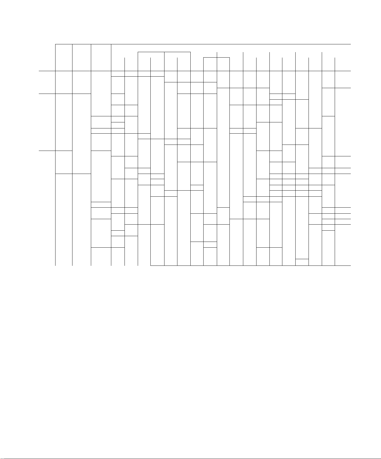
Table 6 — Air Delivery (Cfm) at Indicated External
Static Pressure and Voltage* (Cont)
330
320
520
620
320
520
UNIT
PHASE
(60-Hz)
230-1
208/
230-3
460-3
230-1
208/
230-3
230-1
230-1
BLO WER
MOTOR
SPE ED
Low
High
Low
Med
High
Low
High
Low
High
Low
Med
High
1
High
Low
Med
High
APPLIC A-
TIONt
Heati
Coo l
Heat
Coo li
Heati 1150 139 5 1 150
Cool 1150 1395
Heat
Cool 1800 2050 1 790
Heat 2200 2325 2155
Cooli 2 150 2260 21 05
Heatf
Cool
Heat
Cooli
Heati
Cool
Heat
Cooli
Heat* **
Cool
Heat**
Cooli 1 745 1945 "l730
Heat 1950
Cool 19 20 2125 18 85
Heati
Cool
Heat
Cooli
Heat
Cool
Heati
Cool
Heat
Cooli
VOLTS/
48
0 0 0 1 0 2
208 V
1805
1440
1435
1755
230 V
or
460 V
1350
-
1345
-
1920
1860
-
2080
1500
1490
2040
1995
1790
1745
-
1975
1905
1”730
1720
1970
2175
1585
-
1585
-
2375
-
2235
-
1880
-
1875
-
2130
-
2050
-
2345
-
2210
—
230 V
208 V
or
460 V
1340
1335
1845
1 790
1395 11 50 1395 1150 1390 115 0 1385 1 150
1150 1395 1150 1 390 1150 1385
1800
2050
2015
2275
2205
1480
1465 - 1 445
1995
1950
1730
1685
1900
1835
-
1435
1720
1430 1705 1420
1740 1945 1725 1 910
1915
1920 213 0^
2080 1 845 2030
1585
-
1585
-
2280
-
2150
-
1875
-
1855
-
- 2075
1995
-
2260
-
2135^
-
208 V
1785 20 15 1760
1770
2105
2055
1425
1705
1880 208 5
MODEÌ.
SERIES
GL04S
GH048
GL060
320/
GH060
320/
330
*Air delivery values for all sizes of Models 48GH/GL are without air filter
fHeating airflow values are with a dry coil, Cooling airflow values are with a wet coil
iThese airflow values are at the factory heating and cooling blower motor speed setting
**The heating blower motor speed for these units is factory wired for low speed at 230-v
operation For 208-v operation, the heating speed should be changed to medium See
unit wiring label
EXT ERNAL STATIC PRESS UR E (in
230 V
or
460 V
1330
1320
1770
1720
-
1970
0 3
230 V
208 V
or
460 V
1310
1300
1695
1645
-
1970 1 735 1920 1700 1865 1665
1740
1925 1710 1870 1675
0 4 0 5
230 V
208 V
460 V
1275
1250 - 1150
1620
1575
-
1150 13 80
or
208 V
-
-
-
1145
2220 2 055 2160 2000 2095 1940
2150 2000 2090
1460
-
1950
1900
1665
1625
1820
1760
—
1700 1 415 1675 1400 1645 1385
1685 1 410 1655 1395 1620 1375 1585 1 355
1875 1 675 1835 1 640 1785 1595
1580
-
1575
-
2185
-
2075 1985
-
1860
-
1820
-
2015
-
1940
-
2180
-
_
2060
1435
-
1420
1895
1845
1600
1555
-
1745
-
1690
—
1700 187 0 1665
1840"^
2030 1795
1970
1805
1560
-
1550
-
2095
-
1825
-
1765
-
1955
-
1875
-
2095
-
1985
-
A dash (—) indicates portions of the table that are beyond the blower motor capability or
that are not applicable
NOTE: Do not operate the unit at a cooling airflow that is less than 350 cfm per each
12,000 Btuh of rated cooling capacity Indoor coil icing may occur at airflows below this
point
2030
1940
-
-
-
-
-
-
-
-
1760 19 10 1710 1850 1660 178 0
-
-
-
-
-
-
-
-
-
1880 19 65 1825 1900
^14f0 1380
1395
-
1835
-
1790
-
1530
-
1485
1665
1615
-
1825
1625 Mlb 1580
197Ó 1750 1905 1 700 1840
1530
-
1515
-
__
2000
1905
-
1770
-
17Ò Ò
-
1890
-
1800 1705
2010
-
1910
-
wg)
0 6 0 7
230 V
or
208 V
460 V
1190
1550
1505
1370
1365 1 140 1345
1815
2030
1365
1775
1725
1450
1400
1590
1545
Ì61 o”"
1730
1495
1475
1905
1820
1700
1625
1810
1930
1835
460 V
- - -
- - - - - -
- - - - -
-
1145
1635
1880
^ 1350
-
- 1340 1310 —
-
-
- - -
- - - - -
- - - - -
- - - - -
1365™'
1 550
- - - - -
- - - - - -
- - - - -
- - - - - -
- - - - - -
- - - - — -
- -
-
- - - - — -
-
0 8
230 V
or
-
1355 1135 1330 1115
1805
1755 1595 1700
1965 18 15
1710
1665 1 600
1565
1540
1720 1525 1660
1675
— — - — —
- - ~ -
230 V
or
208 V
~ - - -
1130
1625
1765 183 5 1705
-
- ^
1340 1 520 1305
1325 14 90 1285
1495 16 20
1645
Ì610 1 715 1555
__
208 V
460 V
-
1320
1745 1 585
1895
1325 -
1645
1
- -
1765
- —
-
1110 1285
1560 16 40
1755
—
- 1535
1470 16 00
1435 15 60
1590 16 95
230 V
460 V
1680
1825
1770
1290
1280
1555
__
1470
1440
1645
or
-
■
-
15
Page 16

CONTROLS — All compressors have the following
internal-protection controls:
High-Pressure Relief Valve — This valve opens
when pressure differential between low and high
side becomes excessive.
Compressor Overload — This overload interrupts
power to compressor when either current or internal
temperature become excessive, and automatically
resets when internal temperature drops to a safe
level. This overload may require up to 60 minutes (or
longer) to reset; therefore, if internal overload is
suspected of being open, disconnect electrical power
to unit and check circuit thru the overload with an
ohmmeter or continuity tester.
Time Guard II — This solid-state electronic device
assures a 5-minute delay between stop and restart of
unit compressor. This allows for internal pressure to
equalize and permits easy, unloaded start-up with
minimum stress on compressor.
OPERATING SEQUENCE
Heating — The following sequence of operation
pertains to all 208/230-volt, 3-phase units; however,
the sequence of operation of single-phase and 460volt units is very similar. Refer to line-to-line wiring
diagram in Fig. 9.
NOTE: Although actual unit wiring may vary
slightly from that shown in Fig. 9, sequence of
operation will not be affected.
With room thermostat selector switch at HEAT
position and the fan switch at AUTO, position,
heating sequence of operation is as follows:
Models 48GH / GLhave an intermittent RELITEtype pilot without a standing flame. When manual
control valve is opened, gas flows to solenoid valve
chamber of gas valve. Unit is now in a standby
condition and ready for a call for heat from room
thermostat.
When room temperature drops to a point that is
slightly below heating eontrol setting of room
thermostat, thermostat heating bulb tilts and com
pletes circuit between thermostat terminals R and
W. This completed circuit between R and W thru
room thermostat simultaneously energizes pilot gas
valve (part of gas valve) and pilot igniter. The
energized pilot gas valve permits gas to flow to pilot.
NOTE: Pilot gas valve is a solenoid consisting of a
PICK and a HOLD coil. Both coils must he ener
gized to open pilot gas valve, but only HOLD coil
must be energized to keep valve open.
Energized pilot igniter sends a high-voltage
charge to pilot electrode (part of pilot). Pilot elec
trode produces a spark that ignites pilot. Flame
sensing monometal switch in pilot proves presence
of pilot flame. Approximately 40 to 60 seconds after
pilot flame is established, normally closed contacts
of pilot open and normally open contacts close.
Switching of pilot contacts de-energizes pilot igniter
and PICK coil of pilot solenoid. HOLD coil of pilot
solenoid is still energized; therefore, pilot gas valve
remains open and pilot remains lit.
WARNING: U' pilot fails
attempi to laanualiy iight intersiatieiji-type;
with a match or other source of fiaTae>
The switching of pilot contacts also completes
low-voltage circuit to time delay relay (heating), and
terminal 1 of gas valve. After approximately 10
seconds, heat-motor-operated gas valve opens and
permits gas to flow to burners where gas is ignited
by pilot. Ignited burners heat the heat exchanger.
After built-in time delay, normally open relay
contacts of energized time delay relay (heating)
close, and circuit to indoor fan motor is completed.
Fan motor starts.
The heating cycle remains on until room tempera
ture rises to a point that is slightly above heating
control setting of room thermostat. At this point,
thermostat heating bulb tilts and breaks circuit
between thermostat terminals R and W. The gas
flow thru gas valve stops and burner flames go out.
Gas flow thru pilot gas valve also stops and pilot
flame goes out.
Time delay relay (heating) de-energizes; however,
there is a built-in delay before heat relay contacts
open, and blower continues to move air across heat
exchanger to help optimize heating efficiency. When
heat relay contacts open, circuit to indoor fan motor
breaks and motor stops.
Unit is in a standby condition, waiting for next
call for heat from thermostat.
Cooling — The following sequence of operation
pertains to all 208/230-volt, 3-phase units; however,
sequence of operation of single-phase and 460-volt
units is very similar. Refer to line-to-line wiring
diagram in Fig. 9.
NOTE: Although actual unit wiring may vary
slightly from that shown in Fig. 9, sequence of
. operation will not be affected.
With room thermostat selector switch in the
COOL position and fan switch in AUTO, position,
cooling sequence of operation is as follows:
When room temperature rises to a point that is
slightly above cooling control setting of thermostat,
thermostat cooling bulb tilts and completes circuit
between thermostat terminal R to terminals Y and G.
These completed circuits thru the thermostat connect
Time Guard II circuit (thru unit wire Y) and indoor
fan relay (cooling) (thru unit wire G) across the 24-
volt secondary of transformer. After a 3-second
delay. Time Guard II circuit energizes contactor.
The 2 sets of normally open contacts of energized
contactor close and complete the circuit thru com
pressor and outdoor fan motor. Both motors start
instantly.
16
Page 17
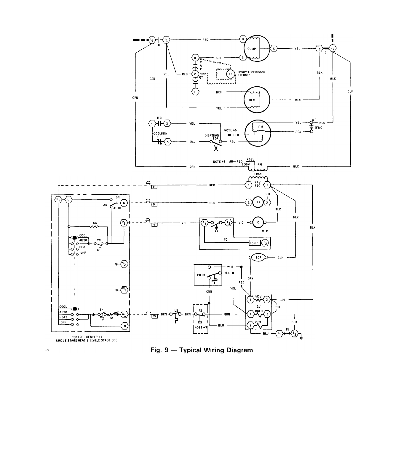
FIELD
POWER
SUPPLY
SCHEMATIC DIAGRAM
The set of normally open contacts of energized
indoor fan relay (cooling) closes and completes
circuit thru indoor fan motor. The blower motor
starts instantly.
The cooling cycle remains on until room tempera
ture drops to a point that is slightly below cooling
control setting of room thermostat. At this point,
thermostat cooling bulb tilts and breaks circuit
between thermostat terminal R to terminal Y and G.
These open circuits de-energize contactor and indoor
fan relay (cooling) and Time Guard II circuit. The
condenser, compressor and blower motors stop. The
unit is in a standby condition, waiting for next call
for cooling from room thermostat. Time Guard II
circuit prevents short-cycling of compressor by a
5-minute time delay between stop and restart.
SERVICE
To ensure continuing high performance, and to
minimize the possibility of premature equipment
failure, periodic maintenance must be performed on
this equipment. This combination heating/cooling
unit should be inspected at least once each year by a
qualified service person.
17
Page 18

Note to Equipment Owner: Consult your local
dealer about the availability of a maintenance
contract.
WARNING; The ability to properly perform
maintenance on this equipment require? cer
tain expertise, mechanical skills, tools and
equipment. If you do not possess these, do
not attempt to perform any maintenance on
this equipment other than those procedures
recommended in the Owner^^ Manual. A
FAILURE TO BEED THIS WARNING
COULD RESULT IN SERIOUS PERSONAL
INJURY AND EQUIPMENT DAMAGE.
The minimum maintenance requirements for
this equipment are as follows:
1. Inspect air filter(s) each month. Clean or
replace when necessary.
2. Inspect cooling coil, drain pan, and condensate
drain each cooling season for cleanliness. Clean
when necessary.
3. Inspect blower motor and wheel for cleanliness
and check lubrication each heating and cooling
season. Clean and lubricate when necessary
4. Check electrical connections for tightness and
controls for proper operation each heating and
cooling season. Service when necessary.
5. Check and inspect heating section before each
heating season. Clean and adjust when necessary.
WARNING: .A failure to follow these warnings
could result in serious personal injury:
1. Turn off gas supply, then diseonnea ekc~
trkal power to the unit before performing
any maintenance or service,
2. Use extreme caution when removing panels
and parts. As with any mechanical equip
ment- personal injury' can result from sharp
edges, etc.
3. Never place anything combustible either on,
or in contact with, the unit.
Top Removal
W.ARNING: When retnoving unit top, use
extreme caution to protect seal that isolates heat
exchanger and flue products from other sec
tions. Removal of top must never be attempted
by anyone other than qualified technicians.
CAUTION; Condenser fan and motor are
fastened to unit top. When removing top, use
extreme care to not pull fan motor leads loose.
NOTE: When performing maintenance or service
procedures that require removal of unit top, be sure
to perform all routine maintenance procedures
that require top removal, including: inspection of
heat exchanger area, coil inspection and cleaning,
and condensate drain pan inspection and cleaning.
When performing maintenance and service
procedures that require unit top removal, refer to
the following top removal procedures:
1. Turn off gas supply, then disconnect electric
power to unit.
2. Remove vent cap and combustion-air assem
blies. Do not damage gasket. (Refer to Venting
section and reverse assembly procedures shown.)
3. Remove all screws that secure unit top, including
screws around 4 sides and those on top that screw
into internal divider panels. Save all screws.
4. Tape all side panels at each seam near unit top.
Use tape strips that are at least 5 in. long to pre
vent sides from falling when top is removed.
5. Carefully lift top from unit. Set top on edge and
ensure that it is supported by unit side that is
opposite duct (or plenum) side. Use extreme care
to prevent damage to the seal that isolates heat
exchanger and flue products or the fan blades,
motor, and insulation.
6. Carefully replace and secure top to unit using
screws removed in step 3 when maintenance
and/or service procedures are concluded. (Be
sure to use original screws that have rubber
washers to seal out water when securing top to
internal divider panels.)
7. Reinstall vent cap and combustion-air assem
blies. (Refer to Venting section.)
Air Filter
C.AUTION: Never operate «nit without a suit
able air filter in retura-air duct system. Always
replace filter with same sire and type. See
Table 1 for recommended filter sizes.
Inspect air filter(s) at least once each month and
replace (disposable-type) or clean (cleanable-type)
at least twice during each heating and cooling season
or whenever the filter(s) becomes clogged with dust
or lint.
Models 48GH/GL do not have factory-supplied
air filters. Field-supplied air filter(s) may be
either disposable or cleanable. Remove access door
on return-air inlet side of plenum to gain access to
filters. See Fig. 1. Replace these filters with same
size and type when necessary.
Evaporator Blower Wheel and Motor — For
longer life, operating economy and continuing
efficiency, clean accumulated dirt and grease from
blower wheel and motor annually.
Fabricate motor every 5 years if motor is used
intermittently (thermostat fan switch in AUTO,
position), or every 2 years if motor is used con
tinuously (thermostat fan switch in ON position).
18
Page 19

WARNiNG: Turn off gas suppiy» then dis
connect electricai power to unit l^fore cieaning
and iubncatbg biower motor and wheei.
Clean and lubricate blower motor and wheel
as follows;
1. Remove and disassemble blower assembly as
follows:
a. Remove blower and control access panels.
b. Refer to unit wiring label and disconnect
blower motor leads from their termination
points in unit control box. (Be sure to mark
wiring label appropriately if lead terminations
were not previously marked.) Pull leads into
blower compartment.
c. Remove blower assembly from unit. Be care
ful not to tear insulation in blower
compartment.
d. Ensure proper reassembly by marking blower
wheel and motor in relation to blower housing
before disassembly.
e. Loosen setscrew(s) that secures wheel to
motor shaft, remove screws that secure motor
mount brackets to housing and slide motor
and motor mount out of housing.
2. Lubricate motor as follows:
a. Thoroughly clean all accumulations of dirt
or grease from motor housing.
b. Remove dust caps or plugs from oil ports
located at each end of motor.
c. Use a good grade of SAE 20 nondetergent
motor oil and put one teaspoon, 5 cc, 3/16 oz,
or 16 to 25 drops in each oil port.
d. Allow time for oil to be absorbed by each
bearing, then wipe excess oil from motor
housing
e. Replace dust caps or plugs in oil ports.
3. Remove and clean blower wheel as follows:
a. Ensure proper reassembly by marking wheel
orientation and cutoff plate location.
b. Remove screws holding cutoff plate, and
remove plate from housing.
c. Lift wheel from housing. When handling
and/or cleaning blower wheel, be sure not to
disturb balance weights (clips) on blower
wheel vanes, and be sure not to drop or bend
wheel.
d. Remove caked-on dirt from wheel and hous
ing with a brush. Remove lint and/or dirt
accumulation from wheel and housing with
vacuum cleaner, using soft brush attachment.
Remove grease and oil with mild solvent.
e. Reassemble wheel and cutoff plate into
housing.
4. Reassemble motor into housing. Be sure setscrew(s) is tightened on motor shaft flats and not
on round part of shaft.
5. Reinstall blower assembly into unit, route
blower leads into control compartment and
reconnect all blower motor leads to proper
termination points in unit control box. Replace
panels.
6. Restore electrical power, then gas supply to unit.
Start unit and check for proper blower rotation
and motor speeds during heating and cooling
cycles.
Heating Section — Ensure dependable and effi
cient heating operating by inspecting heating
section before each heating season and cleaning
when necessary.
Proceed as follows to inspect and clean heating
section:
1. Turn off gas supply, (hen disconnect electrical
power to unit.
2. inspect and clean heating section as follows:
a. Remove control access door.
b. Remove unit top following procedures under
Top Removal.
c. Remove secondary-air shield, flue baffles,
pilot, and burners. (Flue baffles may be re
moved after partial loosening of collector
front panel.) Inspect and clean all of these
components.
d. Clean flue ways with brush and/or vacuum,
and inspect heat exchanger for leaks and
cracks.
e. Inspect indoor-air passages in unit for
cleanliness, and check tightness of screws
and parts.
f. Replace all components removed in step c,
and replace unit top.
3. Restore electrical power, then gas supply to unit.
Start heating cycle and adjust burner air shutters.
See Heating Section Start-Up and Adjustments
- ADJUSTING BURNER AIR SHUTTERS.
WARNING: Never use a match or other flame
to check for gas leaks.
4. Inspect gas control area for gas leaks, using
a soap-and-water solution.
5. Replace control access panel.
Pilot — See Fig. 10. Inspect pilot and clean (when
necessary) at beginning of each heating season.
Remove accumulation of soot and carbon from only
the outside of pilot. The pilot flame must be high
enough to touch the flame-sensing element and to
light burners.
Condenser Coil, Evaporator Coil, and Con
densate Drain Pan — Inspect condenser coil,
evaporator coil, and condensate drain pan at least
once each year. Proper inspection and cleaning
requires the removal of unit top. See Top Removal.
19
Page 20
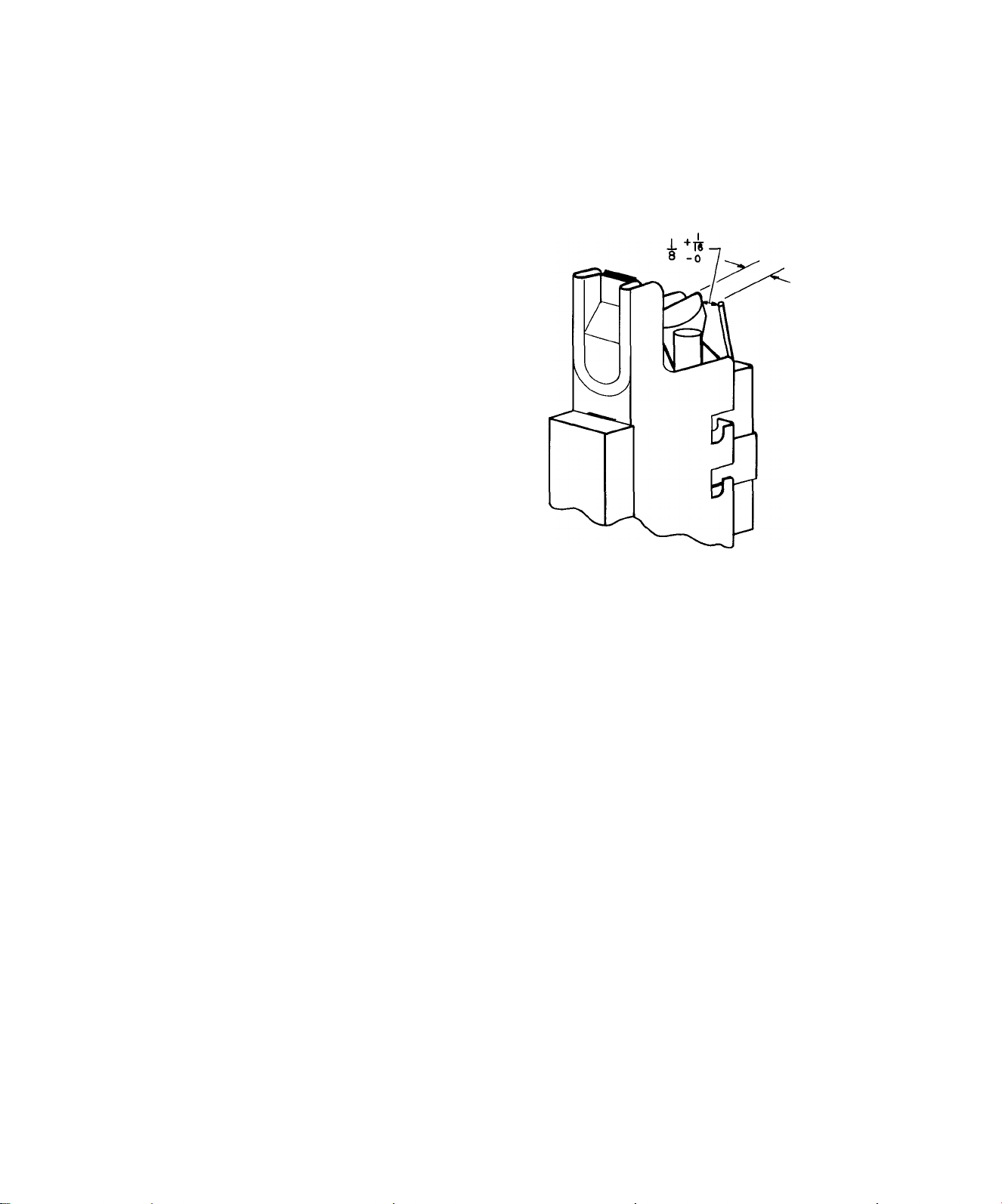
The coils are easily cleaned when dry; therefore,
inspect and clean coils either before or after each
cooling season. Remove all obstructions including
weeds and shrubs that interfere with airflow thru
condenser coil. Straighten bent fins with a fin comb.
If coated with dirt or lint, clean the coils with a
vacuum cleaner, using soft brush attachment. Be
careful not to bend fins. If coated with oil or grease,
clean the coils with a mild detergent-and-water
solution. Rinse coils with clear water, using a
garden hose. Be careful not to splash water on
motors, insulation, wiring, or air filter(s). For best
results, spray condenser coil fins from inside to
outside the unit. On units with an outer and inner
condenser coil, be sure to clean between coils. Be
sure to flush all dirt and debris from unit base.
Inspect drain pan and condensate drain line when
inspecting the coils. Clean drain pan and condensate
drain by removing all foreign matter from pan.
Flush pan and drain tube with clear water. Do not
splash water on insulation, motor, wiring, or air
filter(s). If drain tube is restricted, clear it with a
“plumbers snake” or similar probe device.
The bottom of drain tube has a 1/8-in. diameter
hole. This hole is located in portion of the drain
tube that runs thru drain pan. Clean this hole with a
stiff wire that has a 3/8-in. long, 90 degree bend.
Condenser Fan
check each electrical component with proper elec
trical instrumentation. Refer to unit wiring label
when making these checkouts.
NOTE; Refer to heating and/or cooling sequence
of operation in this publication as an aid in deter
mining proper control operation.
4 -±
16
Fig. 10 — Position of Electrode to Pilot
CAUnON: Keep condenser fan free of all
dbssrtictioiis to eBSiatre proper cooling opera-
tioH. T^ever pfeice articles on top of uniL
Inspect fan blades for cracks or bends each year.
Ensure that blades clear the motor by exactly
I¡4 inch. If blade assembly has slipped down
motor shaft, adjust fan position on motor shaft by
loosening setscrew(s), then moving blade assembly
up. Be sure that setscrews(s) is on flat(s) of shaft
before tightening.
Electrical Controls and Wiring — Inspeet and
check electrical controls and wiring annually. Be
sure to turn off gas supply and then electrical power
to unit.
Remove control, blower, and compressor com
partment access panels to locate all electrical
controls and wiring. Check all electrical connections
for tightness. Tighten all screw connections. If any
smoky or burned connections are noticed: dis
assemble the connection, clean all parts, restrip
wire end, and reassemble connection properly and
securely.
After inspecting electrical controls and wiring,
replace all panels. Start unit, and observe at least
one complete heating cycle and one complete
eooling cycle to ensure proper operation. If dis
crepancies are observed in either or both operating
cycles, or if a suspected malfunction has occurred.
Refrigerant Circuit — Inspect all refrigerant
tubing connections and unit base for oil aceumulations annually. Presence of oil generally indicates a
refrigerant leak.
If oil is detected or if low cooling performance
is suspected, leak-test all refrigerant tubing using
an electronic leak-detector, halide torch, or liquid-
soap solution. If a refrigerant leak is detected, see
Unit Preparation — Refrigerant Leaks.
If no refrigerant leaks are found and low cooling
performance is suspected, see Cooling Seetion
Start-Up and Adjustments — Checking And
Adjusting Refrigerant Charge.
Gas Input — Gas input does not require checking
unless improper heating performanee is suspected.
If a problem exists, refer to Heating Section StartUp and Adjustments.
Evaporator Airflow — Heating and/or cooling
airflow does not require checking unless improper
performance is suspeeted. If a problem exists, be
sure that all supply- and return-air grilles are
open and free from obstructions, and that the air
filter is clean. When necessary, refer to Cooling
Section Start-Up and Adjustments INDOOR
AIRFLOW AND AIRFLOW ADJUSTMENTS
to check system airflow.
20
Page 21

TROUBLESHOOTING CHARTS
Table 7 — Heating Service Analysis Chart
SYMPTOM
Pilot Will Not Light
Burners Will Not Ignite
Inadequate Heating
Poor Flame Characteristics
CAUSE
No spark at electrode
Spark shorting out to main
burner
____
__
No gas at pilot burner
Water in gas line
No power to furnace
No 24-volt power supply to
control circuit
_________
Miswired or loose connections
Dirty pilot — yellow flame
Pilot burning properly —
sharp blue flame
__
___
Burned out heat anticipator
in thermostat
______
___
No gas at main burners
Broken thermostat wire
Dirty air filter
Gas input to furnace too low
Unit undersized for application
Restricted airflow
Blower speed too low _____
Limit switch cycles main burners
Incomplete combustion results in
Aldehyde odors, (CO), sooting
flame — floating flame
REMEDY
Check air gap between electrode tip and pilot
burner Gap should be as shown in Fig. 10
Readjust as necessary. _
_
____
Clean moisture or dirt accumulation on electrode
ceramic with cloth._____
__________
Cracked ceramic — replace pilot electrode
assembly. _
______
___________
__
Check for loose or broken wiring at and between
spark generator and electrode. Replace wire or
tighten connection as necessary. ______
Check fuses or circuit breaker to ensure voltage
to unit.
Check 24-volt input to spark generator If you read
24 volts and above steps have been completed,
replace spark generator. _ _____
Realign electrode tip away from main burner but
maintain spark gap to pilot burner. See Fig. 10.
Clean pilot orifice.
__
________
_
Check for voltage to terminals 3 and 5 of
gas valve.
____
Check to see if pilot valve is opening Check for
loose or broken wiring connections If no
deficiency is found, replace gas valve
Drain — install water trap.
____________
___
_
Check power supply, fuses, wiring, or circuit
breaker.
_______________________
___
Check transformer — replace if necessary
Check all wiring amd wirenut connections.
Clean pilot orifice.
Replace pilot
Replace thermostat
Check to see if main gas valve is opening. Look
for loose or broken wiring connections If no
deficiency is found, replace valve assembly.
Run continuity check to locate break._ __
Replace filter.
_
_____
__________
Check gas pressure at manifold Clock gas meter
for input. If too low, increase manifold pressure
or replace with correct orifices.
Replace with proper unit — or add additional unit.
Clean or replace filter — or remove any
restriction.
_______ _________
________
_
Use faster speed tap — or install optional blower.
Dirty air filters — clean or replace.____
Registers closed, restricted ductwork — open or
remove restriction.
Check heat anticipator setting on thermostat —
readjust._
_ __ _____
_____
___
Air shutters on burners closed — adjust to
soft blue flame. __________________
____
Check all screws around flue outlets and burner
compartment — tighten. _
Lack of combustion air.
Cracked heat exchanger — replace.
__
...............
................
______
.
Overfired furnace — reduce input or change
orifices.
_________ ________ ___
______
Check vent for restriction — clean as required.
Check orifice to burner alignment.
21
Page 22

Table 8 — Cooling Service Analysis Chart
SYMPTOM
Compressor and
Condenser Fan Will
IMot Start
Compressor Will Not Start
But Condenser Fan Runs
Compressor Cycles (other
than normally satisfying
thermostat)
Compressor Operates
Continuously
Excessive Head Pressure
Head Pressure Too Low
Excessive Suction
Pressure
Suction Pressure Too Low
CAUSE
Power failure
Call power company.
Fuse blown or circuit breaker
tripped
Defective thermostat, contactor,
tran^rmer, or control relay
Insufficient line voltage
Incorrect or faulty wiring
Thermostat setting too high
Faulty wiring or loose connections
in compressor circuit
Compressor motor burned out,
seized, or internal overload open
Defective run/start capacitor,
^verload^ startjelay
__
One leg of three-phase power dead
Refrigerant overcharge or
undercharge
Defective compressor
Insufficient line voltage
Blocked condenser
Defective run/start capacitor,
overload, or start relay
Defective thermostat
Faulty condenser fan motor or
capacitor
Restriction in refrigerant system
_Dirty air filter
Unit undersized for load
Thermostat set too low
Low refrigerant charge
Leaking valves in compressor
Air in system
Ccmc^nser coil dirty or restricted
Dirty air filter
Dirty condenser coil
Refrigerant overcharged
Air in system
Condenser air restricted or air
short-cycling
Low refrigerant charge
Compressor valves leaking
Restriction in liquid tube
JHigh heat load '
Compressor valves leaking
Refrigerant overcharged
Dirty air filter
Low refrigerant charge
Metering device or low-side
restricted
Insufficient evaporator airflow
Temperature too low in
conditioned area
Outdoor ambient temperature
beloyy^ F
Field-installed filter drier
restricted
REMEDY
Replace fuse or reset circuit breaker
Replace component
Determine cause and correct
Check wiring diagram and rewire correctly
Lower thermostat setting below room
temperature.
______
Check wiring and repair or replace
Determine cause Replace compressor
Determine cause and replace
Replace fuse or reset circuit breaker Determine
cause.
Blow refrigerant, evacuate system, and recharge
to nameplate
Replace and determine cause
Determine cause and correct
Determine cause and correct.
Determine cause and replace
Replace thermostat
Replace
Locate restriction and remove
Replace filter
Decrease load or increase unit size
Reset thermostat
Locate leak, repair, and recharge
Replace compressor
Blow refrigerant, evacuate system, and recharge
Clean coil or remove restriction
Replace filter
Clean coil
Purge excess refrigerant
Blow refrigerant, evacuate system, and recharge
Determine cause and correct
Check for leaks, repair, and recharge
Replace compressor
Remove restriction
Check lor source and eliminate
Replace compressor
Purge excess refrigerant
Replace filter
Check for leaks, repair, and recharge
Remove source of restriction
Increase air quantity Check filter
replace
jf nej^essary
Reset thermostat
Install accessory low-ambient kit
Replace
For replacement items use Carrier Specified Parts
Manufacturer reserves the right to discontinue, or change at any time, specifications or designs without notice and without incurring obligations.
Book
1
Tab
4
la
la
Form48GH,GL-5SI Supersedes48GH,GL-1 SI
Printed in U.S A
3-82
PC 101
Catalog No 534-820
 Loading...