

Page 1

48XT---A
Infinityr 15 SEER
Single Packaged HYBRID HEATr Du a l Fuel System
with PuronR (R --- 410A) Refrigerant
Owner’s Information Manual
Fig. 1 -- Unit 48XT--A
NOTE TO EQUIPMENT OWNER:
For your convenience, please record the model and serial numbers of your new equipment in the spaces
provided. This information, along with the installation data and dealer contact information, will be helpful
should your system require maintenance or service.
UNIT INFORMATION
Model # _____________________________________
Serial # ______________________________________
ACCESSORIES (List type and model #)
_____________________________________________
_____________________________________________
_____________________________________________
NOTE TO INSTALLER:
This manual must be left with the equipment owner.
INSTALLATION INFORMATION
Date Installed ________________________________
DEALERSHIP CONTACT INFORMATION
Company Name_______________________________
Address______________________________________
_____________________________________________
Phone Number _______________________________
Technician Name _____________________________
_____________________________________________
1
Page 2

Note: Installer: This manual should beleft withtheequipment user.
SAFETY CONSIDERATIONS
Improper installation, adjustment, alteration, service maintenance,
or use can cause explosion, fire, electrical shock, or other
conditions which may cause death, personal injury, or property
damage. Consult a qualified installer, service agency, or your
distributor or branch for information or assistance. The qualified
installer or agency must use factory--authorized kits or accessories
when modifying this product. Refer to the individual instructions
packaged with the kits or accessories when installing.
Follow all safety codes. Wear safety glasses, protective clothing,
and work gloves. Have a fire extinguisher available. Read these
instructions thoroughly and follow all warnings or cautions
included in literature and attached to the unit. consult local
building codes, the current editions of the National Fuel Gas
Code (NFGC) NFPA 54/ANSI Z223.1, and the National
Electrical Code (NEC) NFPA 70.
In Canada refer to the current editions of the National Standards
of Canada CAN/CSA--B149.1 and .2 Natural Gas and Propane
Installation codes, and Canadian Electrical Code CSA C22.1
Recognize safety information. This is the safety--alert symbol
When you see this symbol on the unit and in instructions or
manuals, be alert to the potential for personal injury. Understand
these signal words: DANGER, WARNING, and CAUTION.
These words are u sed with the safety--alert symbol. DANGER
identifies the most serious hazards which will result in severe personal injury or death. WARNING signifies hazards which could
result in personal injury or death. CAUTION is used to identify
unsafe practices which may result in minor personal injury or
product and property damage. NOTE is used to highlight suggestions which will result in enhanced installation, reliability, or operation.
!
WARNING
!
FIRE AND EXPLOSION HAZARD
What to do if you smell gas:
1. Do not try to light any appliance.
2. Do not touch any electricalswitch;do not useany phone in
your building.
3. Leave the building immediately.
4. Immediately call your gas supplier from a nearby phone.
Follow the gas supplier’s instructions.
5. If you cannot reach your gas supplier, call the fire
department.
!
ELECTRICAL SHOCK HAZARD
Failure to follow this warning could result in personal injury
and/or death.
Before performing recommended maintenance, be sure the
.
main power switch to unit is turned off and lock--out tag is
installed.
!
FIRE,EXPLOSION, ELECTRICAL SHOCK HAZARD
Failure to follow this hazard warning could result in personal
injury, death and/or property damage.
1. Do not turn off the electrical power to unit without first
turning off the gas supply.
2. Before attempting to start the gas heating section,
familiarize yourself with all the procedures that must be
followed.
WARNING
WARNING
WARNING
FIRE,EXPLOSION, ELECTRICAL SHOCK HAZARD
Failure to follow this warning could result in personal injury,
death or property damage.
Installation and servicing of this equipment can be hazardous
due to mechanical and electrical components. Only trained
and qualified personnel should install repair or service this
equipment.
!
FIRE,EXPLOSION, ELECTRICAL SHOCK HAZARD
Failure to follow this warning could result in personal injury,
death or property damage.
Do not use this unit if any part has been under water.
Immediately call a qualified service technician to inspect the
unit and to replace any part of the control system which has
been under water.
!
CUT HAZARD
Failure to follow this caution may result in personal injury.
When removing access panels or performing maintenance
functions insideyour unit, be awareof sharp sheetmetal parts
and screws. Although special care is taken to reduce sharp
edges to a minimum, be extremely careful when handling
parts or reaching into the unit.
WARNING
CAUTION
!
FIRE, EXPLOSION HAZARD
Failure to follow this warning could result in personal injury,
death, and/or property damage.
Do not attempt to light by hand.
This 48XT--A unit is a small packaged HYBRID HEAT® system
that can utilize both the efficiency of heat pump heating and the
comfort of gas heating. The system will optimize for ideal heating,
depending on several factors. This unit uses Puron
friendly refrigerant, for cooling and heat pump heating.
You may notice your two--stage packaged HYBRID HEAT®
system runs for longer periods of time. Nearly 80% of the time
it’s running, it is operating in low--stage, and your indoor
temperature will remain more consistent with fewer drafts, better
humidity control, enhanced comfort and enhanced energy
efficiency.
Starting or Shutting Off Unit
Note:Your combination heating/cooling unit is equipped with an
automatic direct spark ignition and power combustion blower.
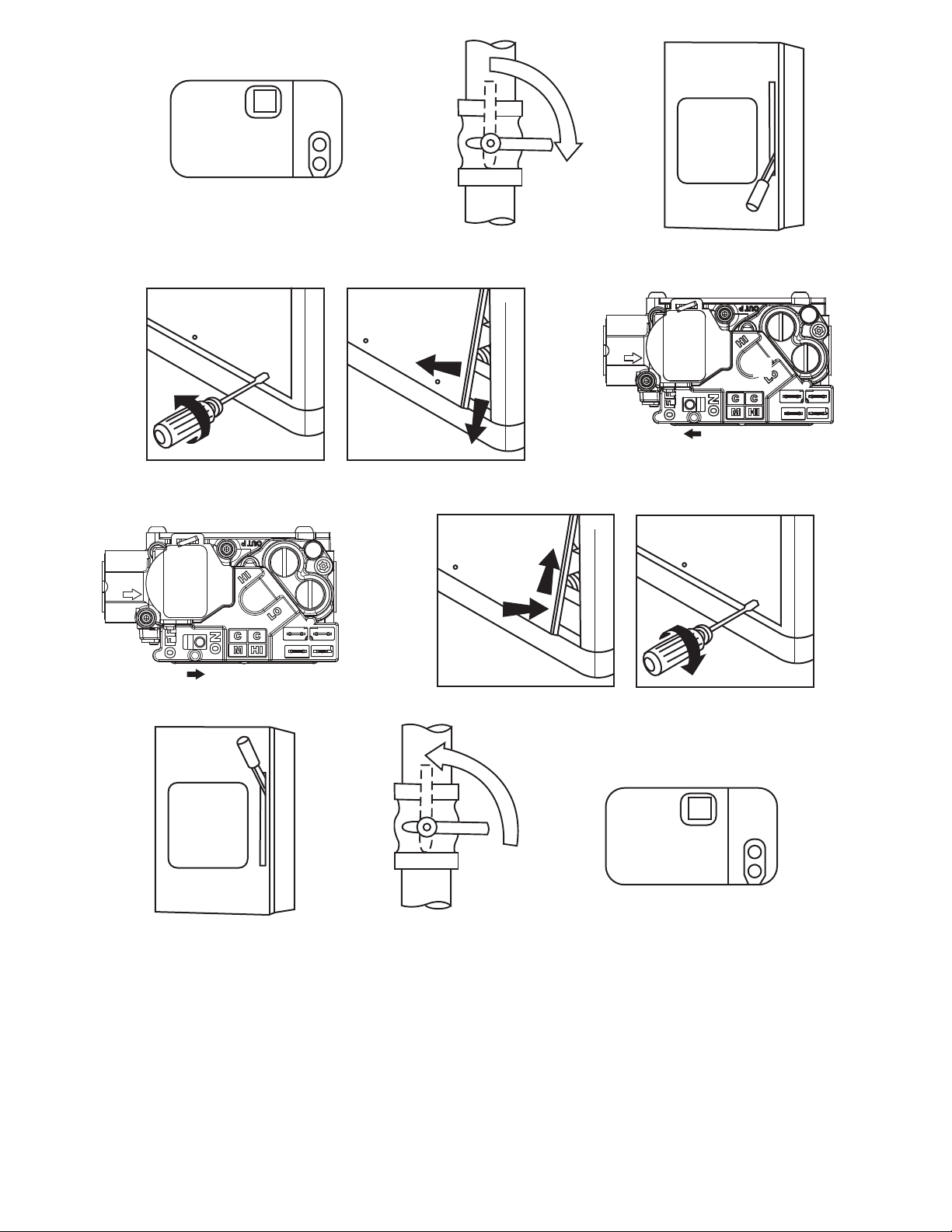
To start unit gas heat:
Refer to Fig.2 for location of unit front access panel. Refer to Fig.
3 for location of gas valve. Refer to Fig. 4 while proceeding with
the following steps.
1. Set the temperatureselector on UI to the lowest temperature
setting and set system switch to Emergency Heat.
2. Close the external manual gas shutoff valve.
2
WARNING
UNIT INTRODUCTION
®
, the ozone
Page 3

3. Turn off the electrical supply to the unit.
4. Remove the front access panel with a 5/16--in. nut driver.
5. Move the selector switch on the internal gas valveto theOFF
position and wait 5 minutes.
6. Move the selector switch on the internal gas valve to the ON
position.
7. Replace the front access panel.
8. Turn on the electrical supply to unit.
9. Open the external manual gas shutoff valve.
10. Set the temperature selector on UI slightly above room temperature to start unit. The induced--draft combustion air fan
will start.Main gasvalve willopen and main burners should
ignitewithin 5 seconds. If the burnerdoes not light within 5
seconds, the ignition module will go into a Retry Mode after
a period of approximately 22 seconds (following the
5--second ignition period). If the burners do not light within
15 minutes of the initial call for heat, there is a lockout.
11. Set the temperature selector on UI to desired setting.
Filter Access Panel
For Accessory Filter Rack
Access Panels
A09045
Fig. 2 -- Accessory Filter Rack Access Panel
Flue Hood
Burners
Gas Valve
A09043
Fig. 3 -- Gas Heating/Electric Cooling Unit with
Access Panel Removed
appearance is shown in Fig. 2.)
(Standard unit shown. Actual
!
FIRE AND EXPLOSION HAZARD
Failure to follow this warning could result in personal injury,
death, and/or property damage.
1. If the main burners fail to light, or the blower fails to start,
shutdown gas heating section and call your dealerfor service.
2. Never attempt to manually light the main burners on unit
with a match, lighter, or any other flame. If the electric
sparking device fails to light the main burners, refer to the
following shutdown procedures, then call your dealer as soon
as possible.
To Shut--off Unit Gas Heat:
!
FIRE, EXPLOSION, ELECTRICAL SHOCK
HAZARD
Failure to follow this warning could result in personal injury,
death, and/or property damage.
Do not turn off the electrical power to unit without first
turning off the gas supply.
Note:If the unit is being shut down because of a malfunction, call
your dealer as soon as possible.
Should overheating occur or the gas supply fail to shut off, shut off
the external manual gas valve to the unit before shutting off the electrical supply. Do not use this unit if any part has been under water.
Immediately call a qualified service technician to inspect the unit
and to replace any part of the control system and any gas control
which has been under water.
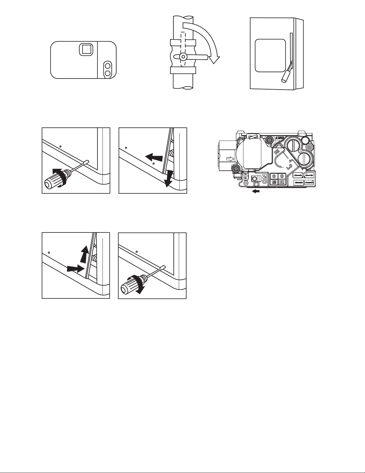
Refer to Fig. 5 while proceeding with the following steps.
1. Set the temperature selector on UI to lowest temperature setting and set system SWITCH to OFF.
2. Close the external manual shutoff valve.
3. Turn off the electrical power supply to the unit.
4. Remove the front access panel.
5. Move the selectorswitchon the internalgas valveto the OFF
position.
6. Replace the front access panel.
To Start Unit Electric Cooling:
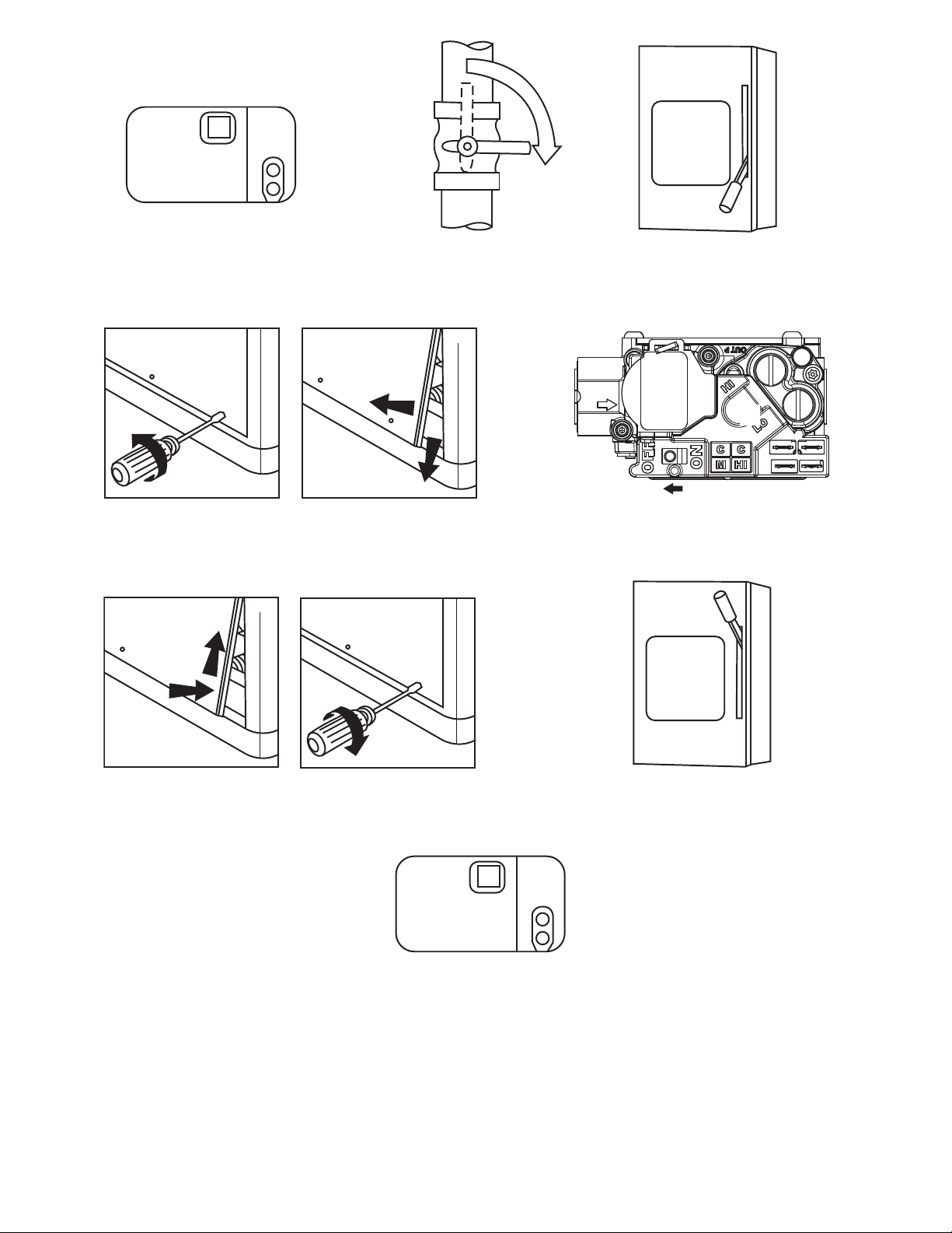
Refer to Fig. 6 while proceeding with the following steps.
1. Set the temperatureselectoron UI to highesttemperaturesetting and set system SWITCH to OFF.
2. Close the external manual shutoff valve.
3. Turn off the electrical power supply to the unit.
4. Remove the front access panel.
5. Move the selector switch on the internal gas valveto theOFF
position.
6. Replace the front access panel
7. Restore electrical power to the unit and set system switch to
COOL.
8. Set the temperature selector on UI slightly below the room
temperature to start unit.
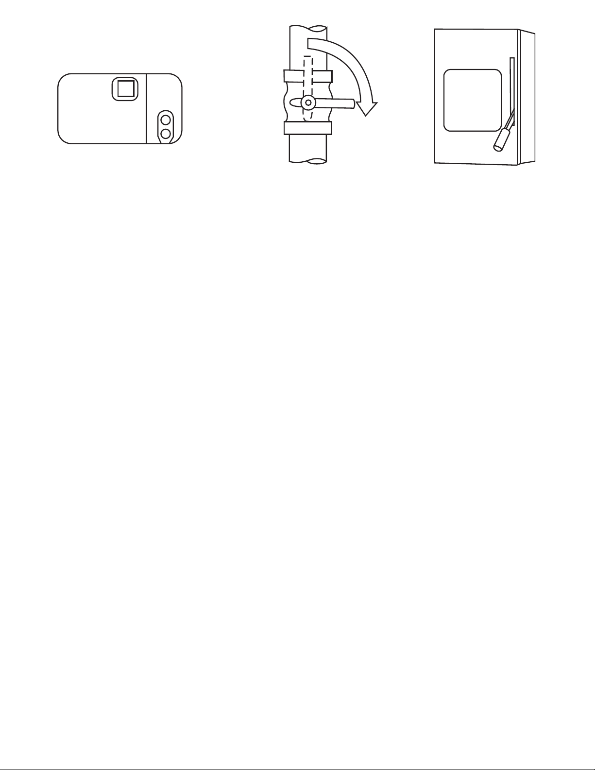
To Shut Off Unit Electric Cooling:
Refer to Fig. 7 while proceeding with the following steps.
1. Set the temperatureselectoron UI to highesttemperaturesetting and set system SWITCH to OFF.
2. Close the external manual shutoff valve.
3
WARNING
WARNING
Page 4
3. Turn off the electrical power supply to the unit.
Note: Heat Pump heating mode procedure is similar to electric
cooling mode except thermostat mode is HEAT and UI must
operate on first stage heating above the balance point that has
been determined by the Dealer.
OPERATING YOUR UNIT
The operation of your unit is controlled by the Infinityr UI. You
simplyprogram the UI and it maintains the indoor temperatureatthe
level you select. See UI manual for detailed instructions.
To better protect your investmentand to eliminate unnecessary service calls, familiarize yourself with the following facts:
!
FIRE,EXPLOSION, ELECTRICAL SHOCK HAZARD
Failure to follow this warning could result in personal injury,
death or property damage.
BEFORE SERVICING OR PERFORMING MAINTENANCE ON YOUR UNIT:
1. TURN OFF GAS SUPPLY TO YOUR UNIT.
2. TURN OFF ELECTRICAL POWER TO YOUR UNIT.
WARNING
!
CAUTION
Step 1—Cooling Mode
With the SYSTEM control set to COOL, your unit will run in cooling mode until the indoor temperature is lowered to the level you
have selected. On extremely hot days, your unit will run for longer
periods at a time and have shorter “off” periods than on moderate
days.
Step 2—Hybrid Heating Mode
Your HYBRID HEAT system combines the strengths of two heating sources; an electric heat pump and a gas furnace. A HYBRID
HEAT system provides more control over your monthly energy
bills by allowing you to choose the most economical method of
heating. As conditions change, the system automatically switches
between the two sources to maintain greater efficiency than with a
single--source heating system.
With the UI controlsetto HEAT, your unit willnormally operatethe
electric heat pump until the room temperature is raised to the level
you have selected.If the demand for heat cannot be metby the electricheat pump, your UI controlwill automatically switchto gas heat
until the call for heat is satisfied.
On colder days, your system may automatically switch to gas heat
as the primary heating source to maximize the overall system efficiency and maintain your comfort level.
When your heat pump needs additional heat to keep you comfortable, your thermostat will turn on the supplemental gas heat.
MAINTENANCE AND SERVICE
CUT HAZARD
Failure to follow this caution may result in personal injury.
When removing access panels or performing maintenance
functions insideyour unit, be aware of sharp sheet metal parts
and screws. Although special care is taken to reduce sharp
edges to a minimum, be extremely careful when handling
parts or reaching into the unit.
Air Filters
The air filter(s) should be checked every 3 or 4 weeks and changed
or cleaned whenever it becomes dirty. Dirty filters produce excessive stresson the blower motor and can cause the motor to overheat
and shut down.
This unit must have air filters in place before it can be operated.
These filters can be located in one of at least two places. In many applications, the installer will provide return air filter grilles mounted
on the wall or ceiling of the conditioned structure. In the instance of
filter grilles, the filters can simply be removed from the grille and replaced.
The other typical application is an accessory filter rack installed inside the unit itself. The following information is given to assist in
changing filters used in these internal filter racks.
Table 1 indicates the correct filter size for your unit. Refer to Fig. 2
to access filters installed in the accessory filter rack.
Table 1—Air Filters Located Inside Unit
(For Replacement Purposes)
Unit Size Quantity Filter Size in. (mm)
A24---A30 2
A36---A60 3
12x20x1
(305X610x25)
12x24x1
(305x610x25)
This section discusses maintenance that should be performed on
your system. Most maintenance should be performed by your dealer. You, as the owner,may wish to handle some minor maintenance
for your new unit.
Routine Maintenance
All routine maintenance should be handled by skilled, experienced
personnel. Yourdealercan help you establish a standardprocedure.
To assureproper functioning of the unit, flow of condenser air must
not be obstructed from reaching the unit. Clearance from the top of
the unit is 48 in. (1219 mm). Clearance of at least 36 in. (914 mm)
is required on sides except the power entry side (42 in.[1067 mm]
clearance) and the duct side (12 in. [305 mm] minimum clearance).
Maintenance and Care for the Equipment Owner
Before proceeding with those things you might want to maintain
yourself, please carefully consider the following:
To replace or inspect filters in accessory filter rack (See Fig. 2):
1. Remove the filter access panel using a 5/16--in. nut driver.
2. Remove the filter(s) by pulling it out of the unit. If the filter(s)
is dirty, clean or replace with a new one.
When installing the new filter(s), note the direction of the airflow arrows on the filter frame.
If you have difficulty locating your air filter(s) or have questions
concerning proper filter maintenance, contact your dealer for instructions. When replacing filters, always use the same size and type
of filter that was supplied originally by the installer.
!
WARNING
FIRE AND UNIT OPERATIONAL HAZARD
Failure to follow this warning could result in death, personal
injury and/or property damage.
Never operate your unit without filters in place. An
accumulation of dust and lint on internal parts of your unit can
cause loss of efficiency.
4
Page 5
Fans and Fan
Periodically check the condition of fan wheels and housingsand fan
motor shaft bearings. Contact your dealer for the required annual
maintenance.
Indoor and Outdoor
Cleaning of the coils should only be done by qualified service personnel. Contact your dealer for the required annual maintenance.
Condensate
The drain pan and condensate drain line should be checked and
cleaned at the same time the cooling coils are checkedby your dealer.
Compressor
Allcompressorsarefactory shipped with a normal chargeof the correct type of refrigeration grade oil. A compressor should rarely require additional oil.
Condenser
PERSONAL INJURY AND UNIT DAMAGE HAZARD
Failure to follow this warning could result in death, personal
injury and/or property damage.
Do not insert sticks, screwdrivers, or any other objects into
revolving fan blades.
The fan must be kept free of all obstructions to ensure proper cooling. Contact your dealer for any required service.
Electrical Controls and W
Electricalcontrolsare d ifficultto checkwithout proper instrumentation. If there are any discrepancies in the operating cycle, contact
your local dealer and request service.
Refrigerant
Therefrigerantcircuitis difficultto checkfor leakswithoutthe proper equipment. If inadequatecooling is suspected, contact your local
dealer for service.
EXPLOSION, BURN AND ENVIRONMENTAL
HAZARD
Failure to follow this warning could result in death, personal
injury and/or property damage.
System under pressure. Relieve pressure and recover all
refrigerant before system repair or final unit disposal. Use all
service ports and open all flow-- control devices, including
solenoid valves.
Unit Panels
Afterperforming any maintenanceor serviceon the unit, be sureall
panels are fastened securely in place to prevent rain from entering
unit cabinetand to prevent disruptionof the correctunit airflow pattern.
Motors
Drain
Fan
!
Circuit
!
Coils
WARNING
iring
WARNING
Regular Dealer Maintenance
In addition to the type of routine maintenance you might be willing
to perform, your unit should be inspected regularly by a properly
trained service technician. An inspection (preferably each year, but
at least every other year) should include the following:
1. Inspection and, if required, cleaning of the outdoor and
indoor coils.
2. Inspection and, if required, cleaning of the indoor coildrain
pan.
3. Inspection and cleaningof blowerwheel housing and motor.
4. Inspection of all supply-- air and return--air ducts for leaks,
obstructions, and insulation integrity. Any problems found
should be resolved at this time.
5. Inspection of the unit baseto ensurethat no cracks, gaps,etc.,
exist which may cause a hazardous condition.
6. Inspection of the unit casing for signs of deterioration.
7. Inspection of all electrical wiring and components to assure
proper connection.
8. Inspection for leaks in the refrigerant circuit. Pressure check
to determine appropriate refrigerant charge.
9. Operational check of the unit to determine working
conditions. Repairor adjustmentshould be made at this time.
Your servicing dealermay offeran economical service contractthat
covers seasonal inspections. Ask for further details.
Completeservice instructions can be found in the unit Installation,
Start--up and Service Instructions.
Warranty Certificate
Your unit has a limited warranty. Be sure to read the warranty carefully to determine the coverage for your unit.
Before you call for service...
...check for several easily--solved problems.
If insufficient heating or cooling is suspected:
( ) Check for sufficient airflow. Check the air filter for dirt. Check
for blocked return--air or supply--air grilles. Be sure they are open
and unobstructed. If these checks do not reveal the cause, call your
servicing dealer.
If your unit is not operating at all, check the following list for
easy solutions:
( ) Check to be sure that the temperature specified by your User
Interface is setbelow the indoor temperature during the cooling season or above the indoor temperature during heating season.Be sure
the User Interface is set to COOL or HEAT and not OFF.
( ) If your unit still fails to operate, call your servicing dealer for
troubleshooting and repairs. Specify the model and serial numbers
of your unit. (Record them in this manual in the space provided.)If
the dealer knows exactly which unit you have, he may be able to
offer suggestions over the phone, or save valuable time through
knowledgeable preparation for the service call.
In Case of Trouble
If you perform the stepsabove and unit performanceis still unsatisfactory, shut off the unit and call your dealer.
5
Page 6
55
MAIN
C
L
O
S
E
ON
OFF
STEP 1 STEP 2
STEP 4
STEP 3
STEP 5
STEP 6
MAIN
STEP 8
ON
OFF
O
P
E
N
STEP 9
Fig. 4 -- To Start Unit Gas Heat
STEP 7
72
STEP 10
A09133
6
Page 7
55
MAIN
C
L
O
S
E
ON
OFF
STEP 1
STEP 4
STEP 2
STEP 3
STEP 5
STEP 6
A09134
Fig. 5 -- To Shut--off Unit Gas Heat
7
Page 8
90
MAIN
C
L
O
S
E
ON
OFF
STEP 1
STEP 4
STEP 2
STEP 3
STEP 5
MAIN
ON
STEP 6
OFF
STEP 7
72
STEP 8
A09135
Fig. 6 -- To Start Unit Electric Cooling
8
Page 9
90
MAIN
C
L
O
S
E
ON
OFF
STEP 1
STEP 2
Fig. 7 -- To Shut--off Unit Electric Cooling
STEP 3
A07797
9
Page 10
HEATING & COOLING
TO OBTAIN INFORMATION ON PARTS: Consult your installing dealer or classified section of your local telephone directory under the
“Heating Equipment” or “Air Conditioning Contractors & Systems” heading for dealer listing by brand name.
Have available the Model No., Series Letter, & Serial No. of your equipment to ensure correct replacement part.
Copyright 2009 Carrier Corporation Edition Date: 03/09
Manufacturer reserves the right to change, at any time, specifications and design without notice and without obligation.
10
Catalog No: OM48XT--- 01
R e p l a c e s : O M 4 8 --- 2 6
 Loading...