


48KHA
Table of contents
 Loading...
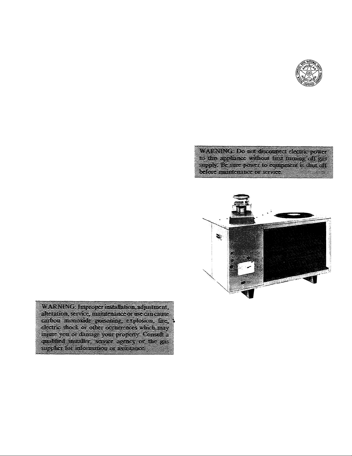
H
Carrier Corporation • Syracuse. N Y 13221
Note to Installer: After installation, leave these instructions, Owner’s Manual and Parts
Replacement Guide with equipment owner.
Packaged Heating/Cooling Units
CONTENTS
SAFETY CONSIDERATIONS
GENERAL .........................................................
INSTALLATION.................................................
Step 1 — Rig and Place Unit
...........................
...........................
• ROOFTOP INSTALLATION
• GROUND LEVEL INSTALLATION
• CLEARANCES
• CONDENSATE DISPOSAL
• VENTING
Step 2 — Make Gas Piping Connections
Step 3 — Make Duct Connections
Step 4 — Make Wiring Connections ...
..................
• HIGH-VOLTAGE CONNECTIONS
• SPECIAL PROCEDURES FOR
208-V OPERATION
• LOW-VOLTAGE CONNECTIONS
• HEAT ANTICIPATOR SETTING
START-UP
SERVICE............................................................
TROUBLESHOOTING CHARTS
.........................................................
......................
Page
. 1
. 1,2
. 2-9
. 2
5
6
7
9-18
18-21
22,23
Use care in handling, rigging and setting bulky
equipment.
Observe precautions in these instructions and on
equipment tags, stickers and labels.
SAFETY CONSIDERATIONS
NOTE: Installation of this unit must conform to the
guidelines presented in these Installation Instruc
tions. Read and beeome familiar with this publica
tion before starting installation.
Only trained, qualified installers and service
mechanics should install, start-up and service this
equipment. Consult the Owner’s Manual for routine
maintenance. All other operations should be per
formed by trained service personnel.
• Follow all safety codes.
• Wear safety glasses and work gloves.
© Carrier Corporation 1984
Fig. 1 — Model 48KHA.KLA
GENERAL
Models 48KHA,KLA packaged gas/ electric units
(Fig. 1) are design certified in accordance with
ANSI Z21.47-1983, ARI Standard 210-81 and ARl
Standard 270-84. The units are design certified by
the American Gas Association (AGA) for use with
natural or propane gases with appropriate eontrols
and orifices. See Table 1 for heating input ratings.
Models 48KHA,KLA units are fully self-contained,
combination gas-heating/electric-cooling units
designed for outdoor installation on either a rooftop
or ground-level slab.
These units are equipped with an energy-saving
automatic, intermittent, electric spark ignition
system that does not have a continuously burning
pilot. All units are manufactured with natural gas
controls.
Form 48KH,KL-9SI
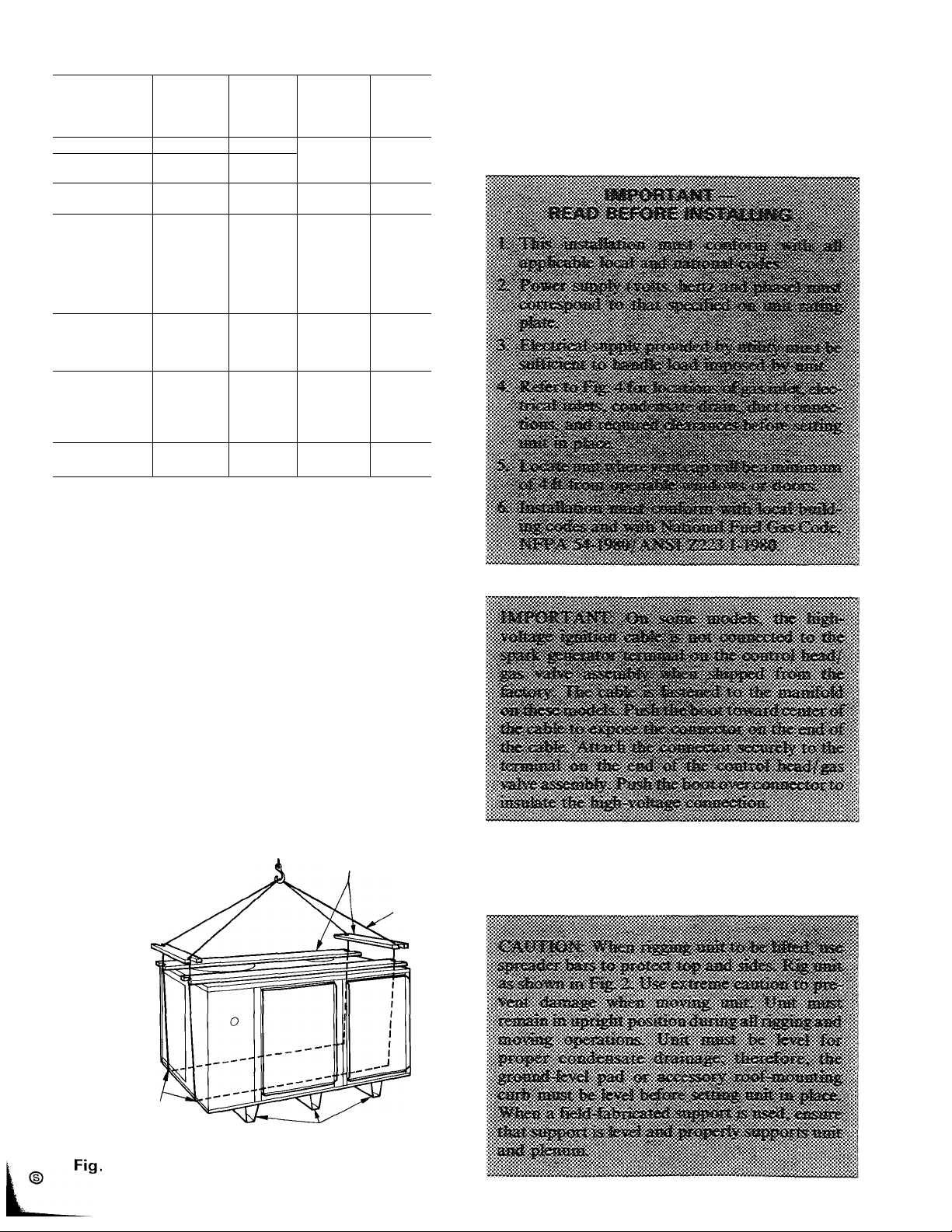
Table 1 — Perferjpiance Data
MODEL 48-
KLA118310BE
KLA124310BE 23,800
KHA024310BF
KLA130310BE
KHA030310BF
KLA136310BE
KLA036510CE
KLA036610CE
KHA136310BE
КНА036510СЕ
KHA036310BF
KHA036510CF
KLA142310BE
KLA042510CE
KHA042310BF
KHA042510CF 42,000
KLA148310BE
KLA048510CE
KLA048610CE 49,000 80,000
KHA048310BF
KHA048510CF
KLA160310BE
KHA060310BF
*Rated in accordance with U S Government DOE test procedures and/or
ARI Standard 210-81
tSound rating per ARI 270-84
^The capacity ratings of single-phase units are in accordance with U S
Government DOE test procedures and/or AGA certification require
ments For 3-phase units, the efficiency rating is a product thermal
efficiency rating determined under continuous operating conditions,
independent of any installed system
COOLING
CAPACITY
(Btuh)*
17,800
24,000
29,600 40,000
29,600
36,000
36,000
36,000 60,000
36,000 100,000
36,000
36,000
36,000
42,000
42,000
42,000
49,000
49,000
49,000 125,000 97,000
49,000 125,000
60,000 100,0001:
60,000 1 50,0001
RATED
HEATING
INPUT
(Btuh)
40,000
40,000
75,000 58,000
75,000 58,000
60,000
60,000 45,000
100,000
125,000 97,000
1 25,000
60,000 47,000 78
60,000 45,000
125,000 97,000
125,000
80,000
80,000 60,000
OUTPUT
CAPACITY
(Btuh)
32,000
32,000
32,000
47,000
45,000
79,000
75,000 80
93,750
93,750
63,000
60,000
93,750
79,000$
11 6,0001
ARIt
SOUND
RATING
(Bels)
7.8
7 8
8.0
7 8
7.8
8 0
80
8 0
80
80
8.0
7 8
7 8
7.8
8 4t
8 41
8 41
8 41
8.41
8 41
8 41
handle an airflow of350 to 450 cfm per each 12,000
Btuh of rated coaling capacity. See Table 8 for cool
ing and heating airflow requirements.
NOTE: When installing any accessory item, see
Installation Instructions packaged with accessory.
Units with number 1 in the 4th digit location of
model number in Table 1 meet California oxides of
nitrogen (NOx) maximum emission requirements.
Units are factory charged with R-22 refrigerant.
To install; connect gas supply, air ducts, high- and
low-voltage wiring and condensate drain, and install
a field-supplied air filter in the return-air ductwork.
All units can be connected into existing duct
systems that are properly sized and designed to
SPREADER BARS:
(2)2x4"xUNIT LENGTH PLUS lO" WITH
DEEP 90° NOTCHES EA(iH END
(2) ¿iiAxUNIT WIDTH WITH 1^
DEEP 90° NOTCHES
EACH END
LOCATE CHAINS THROUGH
HOLES IN BASE
CHANNELS
2 — 48KHA.KLA Suggested Rigging
TWO OR THREE BASE
CHANNELS ATTACHED TO
BOTTOM OF UNIT
SPREADER BARS
CHAIN
Step 1
INSTALLATION
Rig and Place Unit
ROOFTOP INSTALLATION
If installation requires draining the condensate
water away from unit, connect a drain tube using a
minimum of 7/8-in. OD copper tubing, 3/4-in.
galvanized pipe or 7/8-in. plastic pipe.
là
undersize the tube. Pitch drain tube downward at a
Do not
slope at least one in. for every 10 ft of horizontal run.
Be sure to check drain tube for leaks.
When installing a Model 48KHA,KLA end dis
charge unit with a field-supplied downflow plenum,
a field-supplied roof-mounting curb must be in
stalled on and flashed into roof before unit installa
tion. When installing a Model 48KHA,KLA end
discharge unit without a downflow plenum, place
Condensate water can be drained directly onto
roof in rooftop installations (where permitted) or
onto a gravel apron in ground level installations.
When using a gravel apron, make sure it slopes away
from the unit.
unit on a level base that provides proper support.
On flat roofs be sure unit is located at least 4 in.
TO DRAIN
above highest expected water level on roof to
prevent flooding. Consult local codes for additional
installation requirements.
GROUND LEVEL INSTALLATION — Place unit
on a solid, level concrete pad that is a minimum
of 4 in. thick and that extends approximately 2 in.
beyond casing on all sides of unit. Do not secure unit
to pad except when required by local codes.
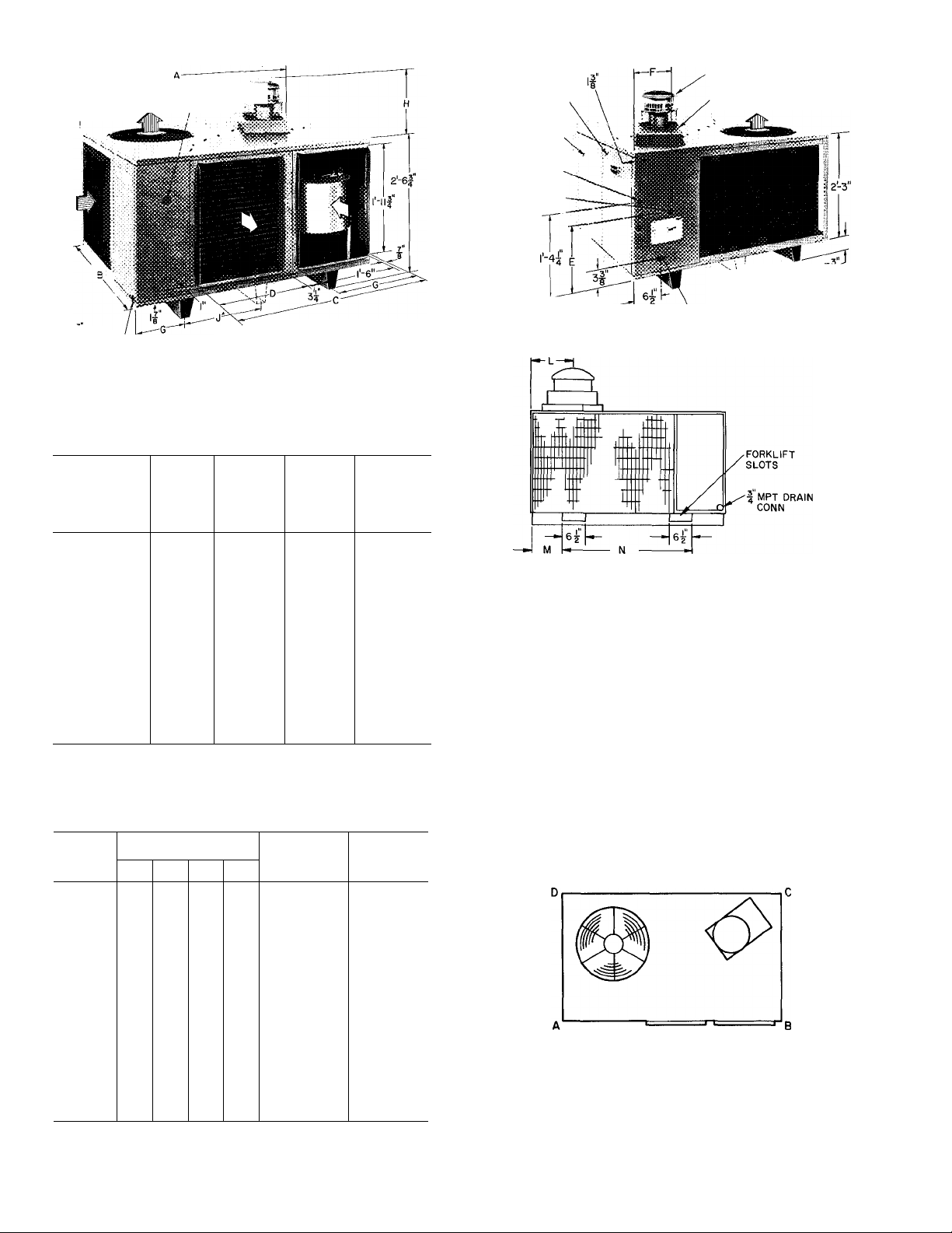
CLEARANCES — Required minimum operating
and service clearances are shown in Fig. 4 for pro
viding adequate combustion, ventilation and con
denser air.
VENTING — The vent cap, combustion air shroud
and flue assembly are shipped in either the blower or
control compartment. Vent screen is taped to blower
housing. Remove access doors to locate assemblies.
See Fig. 4 for door locations.
Condenser fan discharges through top of unit.
Ensure that fan discharge does not recirculate to
condenser coil. Do not locate unit in either a corner
or under a complete overhead obstruction. Mini
mum clearance under a partial overhang (such as a
typical house roof overhang) is 3 ft above vent cap.
Maximum horizontal extension of a partial over
hang must not exceed 4 feet.
Do not locate unit where water, falling ice or snow
from an overhang or roof will damage or flood the
unit. Do not locate unit where grass, shrubs or other
plants will interfere with the airflow either into or
out of unit. Do not install unit on carpeting, tile or
other combustible material other than wood
flooring.
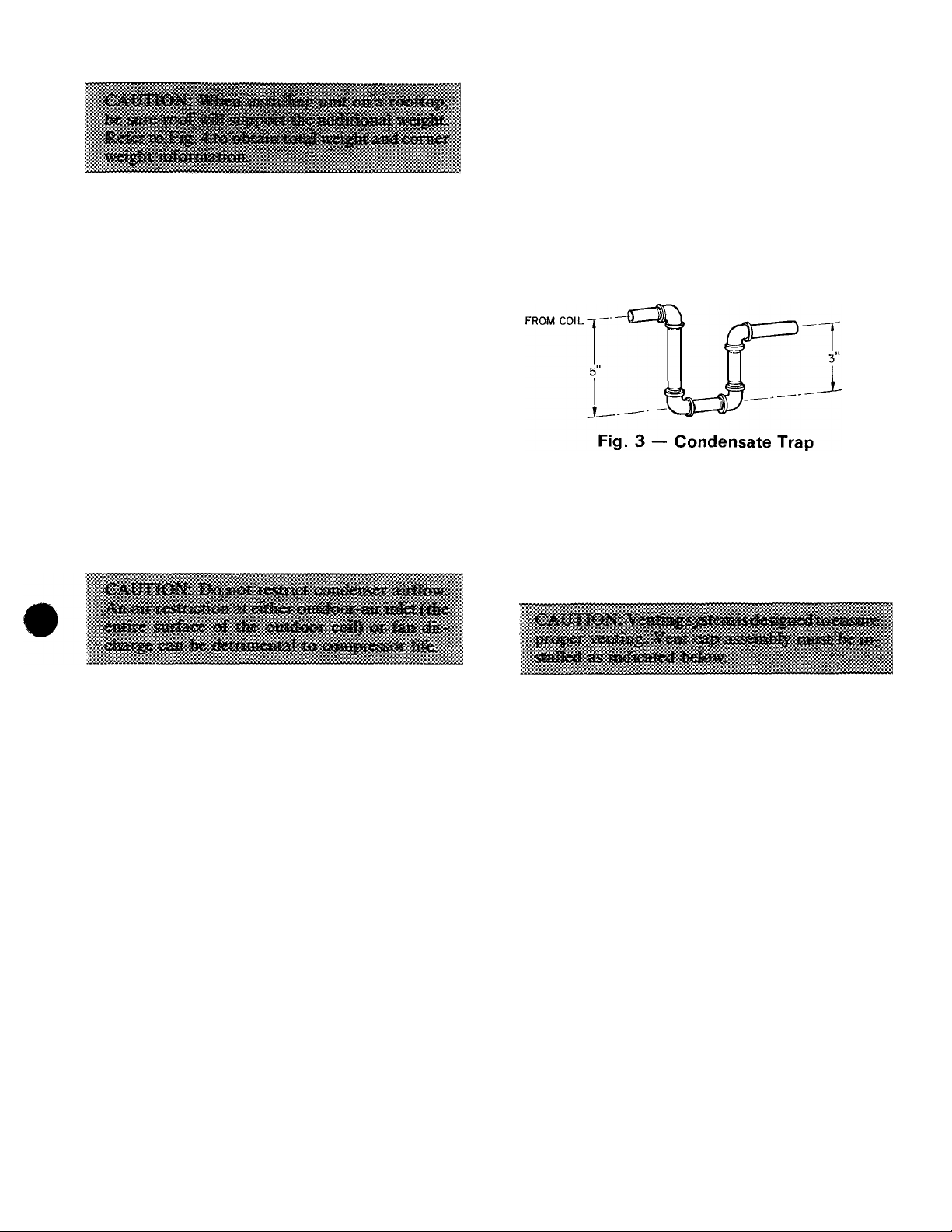
CONDENSATE DISPOSAL
NOTE: Be sure condensate water disposal methods
comply with local codes, restrictions and practices.
Models 48KHA,KLA dispose of condensate
water through a 3/4-in. MPT drain fitting. See
Fig. 4 for location.
Install a 3-in. trap at the drain fitting to ensure
proper drainage. See Fig. 3. Make sure trap outlet
is at least 2 in. lower than unit drain pan connection
to prevent pan from overflowing. Prime trap with
water.
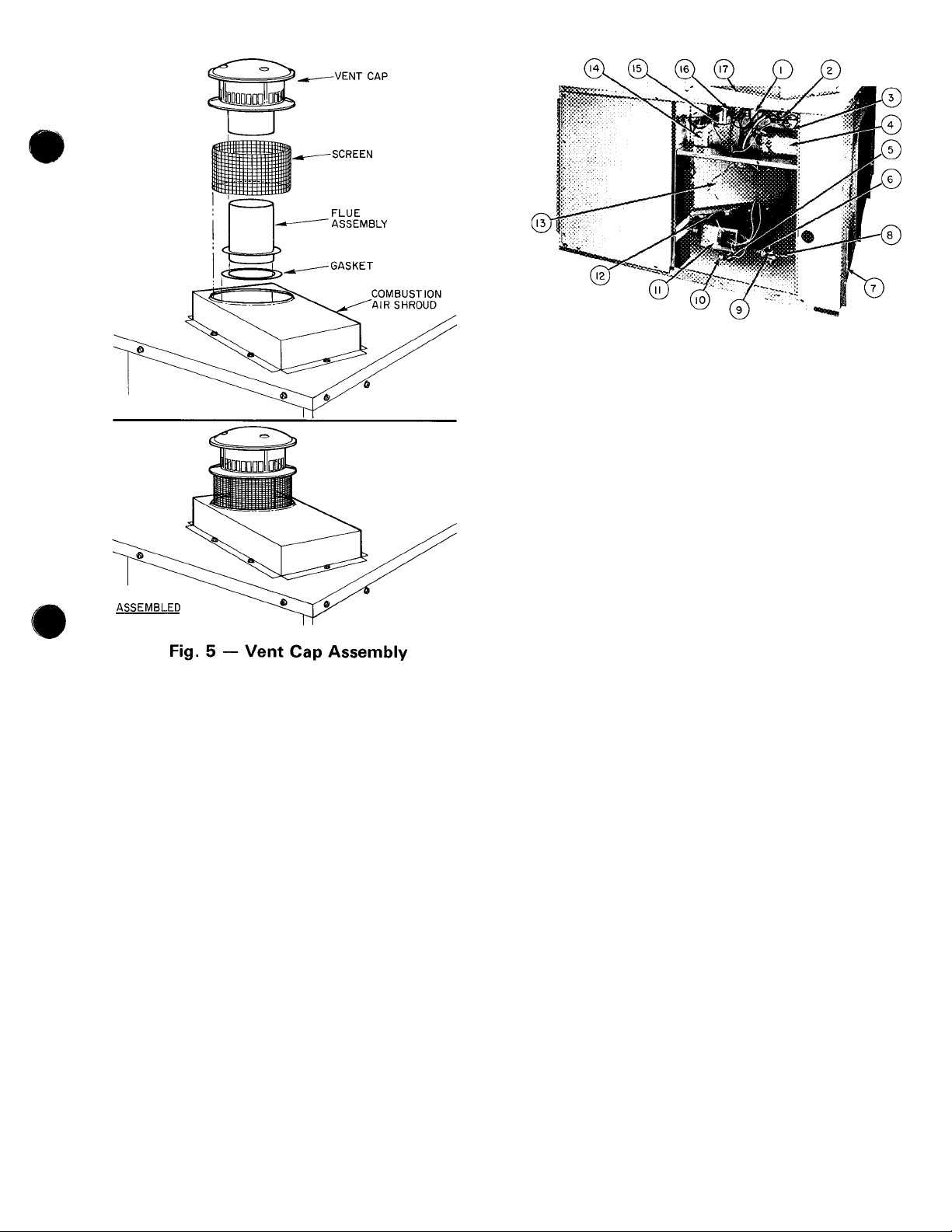
NOTE: Screw holes in flue assembly and unit top
are positioned to ensure proper orientation when
installed. Refer to Fig. 5 and install vent cap as
follows;
1. Place combustion air shroud over combustion air
opening in unit top, and line up screw holes in
shroud with holes in top. Secure shroud to top,
using screws with rubber washers (provided).
2. The flue gasket is shipped in the literature as
sembly envelope. Place gasket and flue assembly
through hole in combustion air shroud, orient
screw holes in base of flue assembly with holes in
unit top, and secure gasket and flue assembly to
unit top, using screws provided.
3. Form flat wire screen (provided) into circular
shape around protruding lip of combustion-air
shroud and bend wire ends through holes of
screen mesh to secure screen in place. Make sure
that no sharp edges are left exposed.
4. Place vent cap sleeve inside flue assembly. Orient
spring clip of vent cap with slot in assembly. Be
sure clip snaps into slot to secure clip onto
assembly.
# MPT
PLUGGED ACCESS HOLE ”
FOR REFRIGERANT j!lH
PRESSURE GAGE HOSES
drain conn
*NOTON MODELS48KLAII8 THROUGH
136¡ KHA024 THROUGH 030.
CONTROLS ACCESS
DOOR
BLOWER ACCESS
DOOR
* LOW VOLTAGE
INLET
K HIGH VOLTAGEINLET
C> EVAPORATOR AIRFLOW
¿CONDENSER AIRFLOW
■VENT CAP
COMBUSTION AIR INLET BOX
V ^4
NOT ON MODELS
48KLAII8 THROUGH 136;
FPT GAS
INLET
KHA024 THROUGH 030
MODEL 48-
KLA118
KLA124
KHA024
KLA130
КНАОЗО
KLA136
KLA036
КНА136
кнАОзе
KLA142
KLA042
КНА042
Dimensions
(ft-in.)
A
B
4- 5%
2- 6% 3- 4% 3- 8%
C 3- 2Vb 3- 5Ув
D
E 1- 4
1- 4 1-7
4- 5% 5- 5%
3-10У8 4- 6У8
2- 0 2-8
1-4 1- 1У4
F 0- 7У4 0- 8Уе 0- 8Ув
G
H 1- ЗУ4 1- ЗУ4 1- 8У4 1- 8У4
J
K
L
M
0-11%
—
0- 1Уз2
0- 1У8
0- 4 Мб
N 1-10
MODEL
48-
KLA118
KLA124 83
КНА024
KLA130
КНАОЗО
KLA136
KLA036
КНА136
КНА036
KLA142
KLA042^
КНА042
KLA148
KLA048
КНА048
KLA160
КНА060
CORNER WT (Ib)
A В
82 79
81 79
96
94
97
93 90 92 372
97
93 91 94
98 97 92
98 97 92
122
120 116 117 475
122
120 116 117 475
108 105 102
108
105 102 105 420
113 111 107
130
135
130
135 137
134
139
144
148
155 151
0-10% 0-10%
—
0- 1У8 0- 1%
0- 1У8
0- 6 Мб
2-4 2- 4
С D
'“'ТР
79
82
94
91
93
93 380
105
109 440
137
133 535
133
144
138
144
139
148
151
1-10'Уз2
1- 4 1-5
0- 8Мб 0- 8Уб
TOTAL
OPERATING
WT (lb)
320
325
375
375
380
420
535
555
575
605 615
KLA148
KLA048
КНА048
KLA160
КНА060
6- 0%
3- 8%
1- 1У4
0- 8Уе
0-1 1У8
2- ОзУз2
0- 1%
2-4
Weight Data
TOTAL
SHIPPING
WT (lb)
330
335
385
382
385
390
390
485
485
430
430
450
545
545
565
585
VIEW AA
CLEARANCES (ft-in.)
Above flue vent .. ................................... 3-0
Duct side of unit
.............................
.
................
0-6
Side opposite ducts...................................................... 2-6
Blower access panel side ... ...
..............
2-6
Side opposite blower access panel............................................... 2-6
Bottom of unit
......................
.................... .. .. ....0
NOTE: Provision must be made for fresh ambient air to reach the
outdoor coil without recirculation of the air from the outdoor fan
discharge
L
Fig. 4 — Dimensions and Clearances (ft-in.)
4
Step 2 — Make Gas Piping Connections — A
manual shutoff valve is shipped loose in the burner
compartment or blower compartment. Connect one
end of a field-supplied 1/2-in. straight nipple to the
gas valve inlet. Connect the other end of the nipple
to the manual shutoff valve as shown in Fig. 6. The
gas supply pipe enters unit through access hole pro
vided. See Fig. 4 for location. The gas connection to
unit is made to the 1/2-in. FPT gas inlet on manual
shutoff. See Fig. 6 for inlet location.
Install a separate gas supply line that runs directly
from meter to heating section. Do not use cast-iron
pipe. Check local utility for recommendations con
cerning existing lines. Choose a supply pipe that is
large enough to keep pressure loss as low as prac
tical. Never use pipe smaller than the 112-in. FPT
gas inlet on unit manual shutoff.
When installing gas supply line, observe local
codes pertaining to gas pipe installations. Refer to
National Fuel Gas Code, NFPA 54-1980/ANSI
Z223.1-1980 in absence of local building codes.
Adhere to following pertinent recommendations:
1
Control Transformer 9
2
Compressor Contactor 10
3
Ground Lug
4
Dual Run Capacitor 11
(for compressor and 12
condenser fan motor) 13
5
Gas Valve
6
1/2-in Nipple 14
7
Gas Pipe
Entrance Hole 15
Gas Inlet 16
Pressure Tap 17
Manual Shutoff
Regulator, Adjustment
Cover Screw
Electronic Control Head
Secondary-Air Shield
Low-Voltage Pigtail
Leads
Blower Motor Run
Capacitor
Heating Relay
Cooling Relay
Combustion Air Shroud
Fig. 6 — Model 48KLA036 — Side View
(Partial) with Access Doors Removed
1. Avoid low spots in long runs of pipe. Grade all
pipe I /4 in. in every 15 ft to prevent traps. Grade
all horizontal runs downward to risers. Use risers
to connect to heating section and to meter.
2. Protect all segments of piping system against
physical and thermal damage. Support all piping
with appropriate hangers, etc. Use a minimum of
one hanger in every 6 feet. For pipe sizes larger
than 1 / 2 in., follow recommendations of national
codes.
3. Apply joint compound (pipe dope) sparingly and
only to male threads of joint when making pipe
connections. Use only pipe dope that is resistant
to action of liquefied petroleum gases as speci
fied by local and/or national codes. Never use
pipe thread tape.
4. Install a sediment trap in riser leading to the heat
ing section. See Fig. 7. This drip leg functions as a
trap for dirt and condensate. Install trap where
condensate cannot freeze. Install this sediment
trap by connecting a piping tee to riser leading to
heating section, so that straight-through section
of tee is vertical. Then, connect capped nipple
into lower end of tee. Extend capped nipple
below level of gas controls.
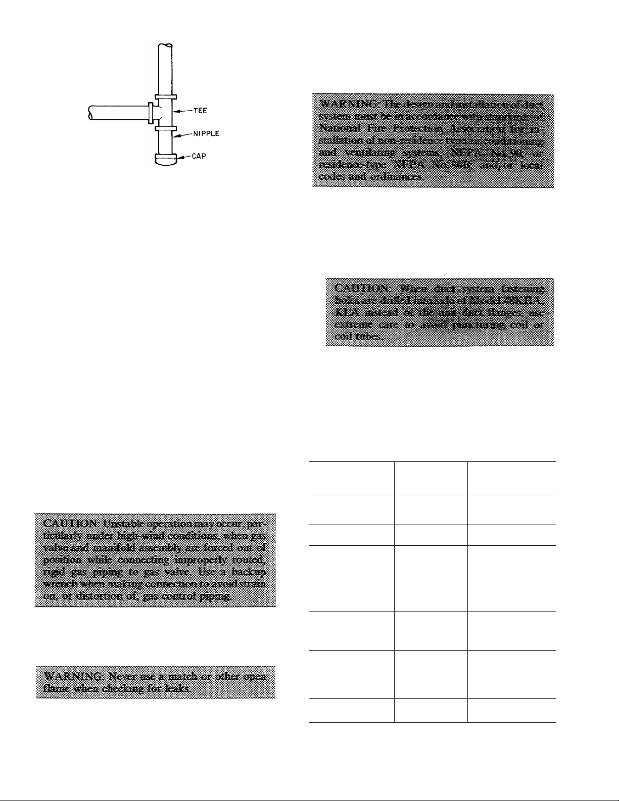
Fig. 7 — Sediment Trap
Step 3 — Make Duct Connections — Model
48KHA,KLA has duct flanges on the supply-and
return-air openings on side of unit. See Fig. 4 for
connection sizes and locations.
5. Install an accessible, external, manual shutoff
valve in gas supply pipe within 6 ft of heating
section.
NOTE: The unit manual shutoff valve has a
1/8-in. tapping on the inlet side of this shutoff
for measuring gas input pressure.
6. Install ground-joint union close to heating sec
tion between unit manual shutoff and external
manual main shutoff valve.
7. Pressure-test all gas piping in accordance with
local and national plumbing and gas codes before
eonnecting piping to unit.
NOTE: When pressure-testing the gas supply
system after the gas supply piping has been con
nected to the unit gas valve, the supply piping
must be disconnected from the gas valve during
any pressure testing of the piping systems at test
pressure in excess of 0.5 in. psig. When pressure
testing the gas supply piping system at test pres
sures equal to or less than 0.5 in. psig, the unit
heating section must be isolated from the gas
piping system by closing the external main
manual shutoff valve and slightly opening
ground-joint union.
8. Where permitted by local codes, use an approved
corrugated metal tubing gas connector between
rigid gas piping and unit manual shutoff.
9. Check for gas leaks at all field-installed and
factory-installed gas lines after all piping connec
tions have been completed. Use soap-and-water
solution (or method specified by local codes and/
or regulations).
Adhere to the following requirements when se
lecting, sizing and installing duct system:
1. Select and size ductwork, supply-air registers and
return-air grilles according to ASHRAE recom
mendations and as presented in Carrier System
Design Manual, Part 2.
2. Use a flexible transition between rigid ductwork
and unit to prevent transmission of vibration.
The transition may be screwed or bolted to duct
flanges. Use suitable gaskets to ensure a weathertight and airtight seal.
Table 2 — Filter Sizes (Field Supplied),
(Sq In.)*
STANDARD
MODEL 48-
KLA118310BE
KHA024310BF
KLA124310BE
KHA030310BF
KLA130310BE
KHA036310BF
KHA036510CE
KHA036510CF
KHA136310BE
KLA036510CE
KLA036610CE
KLA136310BE
KHA042310BF
KHA042510CF
KLA042510CE
KLA142310BE
KHA048310BF
KHA048510CF 768
KLA048510CE
KLA048610CE
KLA148310BE 768
KHA060310BF
KLA160310BE
*Required air filter areas shown are based on the ARI-rated cooling
airflow or the heating airflow at a velocity of 300 fpm depending
on whichever value is larger Air filter pressure drop should not
exceed 0 08 in wg
DISPOSABLE
TYPE
302 202
454
384 257
480 320
480 320
694 462
576 384
694 462 .
576 384 >
576 384
576 384
576 384
694 462
694
672 448
672 448
768
768 512
768 512
960 640
960
CLEANABLE OR
HIGH CAPACITY
TYPE
303
462
512
512
512
640
L
3. Install external, field-supplied air filter(s) in
return-air ductwork where it is easily accessible
for service. Recommended filter sizes are shown
in Table 2.
4. Size all ductwork for maximum required airflow
(either heating or cooling) for unit beinginstalled.
Avoid abrupt duct size increases or decreases.
5. Adequately insulate and weatherproof all duct
work located outdoors. Insulate ducts passing
through an unconditioned space, and use a vapor
barrier in accordance with the latest issue of
SMACNA and NESCA minimum installation
standards for heating and air conditioning
systems. Secure all ducts to building structure.
6. Flash, weatherproof and vibration-isolate all
openings in building structure in accordance with
local codes and good building practices.
Step 4 — Make Wiring Connections
4. When low-voltage control wires are run in same
conduit as high-voltage wires, insulate lowvoltage wires for highest voltage contained within
conduit.
5. Do not damage internal components when drill
ing through any panel to mount electrical
hardware, conduit, etc.
HIGH-VOLTAGE CONNECTIONS — Unit must
have a separate electrical service with a fieldsupplied, waterproof, fused disconnect switch per
NEC mounted near, and within sight from, the unit.
Refer to unit rating plate for maximum fuse size and
minimum circuit amps (ampacity) for wire sizing.
Table 3 shows recommended wire sizes and lengths
based on rating plate data.
The field-supplied disconnect switch box may be
mounted on unit over the high-voltage inlet hole in
control corner panel. See Fig. 4.
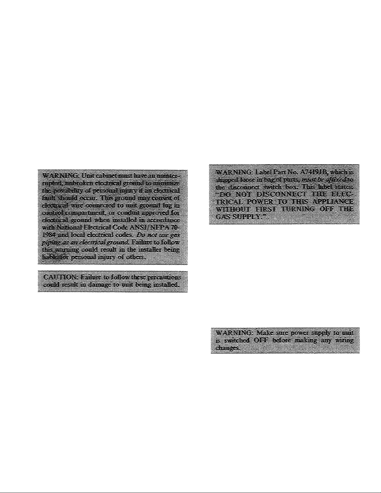
1. Make all electrical connections in accordance
with National Electrical Code ANSI/NFPA 70-
1984 and local electrical codes governing such
wiring.
2. Use only copper conductor for connections
between the field-supplied electrical disconnect
switch and the unit. Do not use aluminum or
copper-clad aluminum wire.
3. Ensure that high-voltage power to unit is within
operating voltage range indicated on unit rating
plate. On 3-phase units, ensure that phases are
balanced within 2%. Consult local power
company for correction of improper voltage
and/or phase balance.
Proceed as follows to complete the high-voltage
connections to unit:
1. Connect ground lead to chassis ground connec
tion when using a separate ground wire.
2. Run high-voltage leads into unit control box and
connect to contactor. See unit wiring label and
Fig. 6 and 8.
NOTE: On 3-phase units, connect third high-voltage
lead to brown high-voltage pigtail lead. See unit
wiring label and Fig. 8.
SPECIAL PROCEDURES FOR 208-V
OPERATION
For operation on 208 volts, disconnect orange
transformer-primary lead from contactor. See unit
wiring label and Fig. 6. Remove tape and cover from
terminal on end of red transformer-primary lead.
Save cover. Connect red lead to contactor terminal
from which orange lead was disconnected.
#
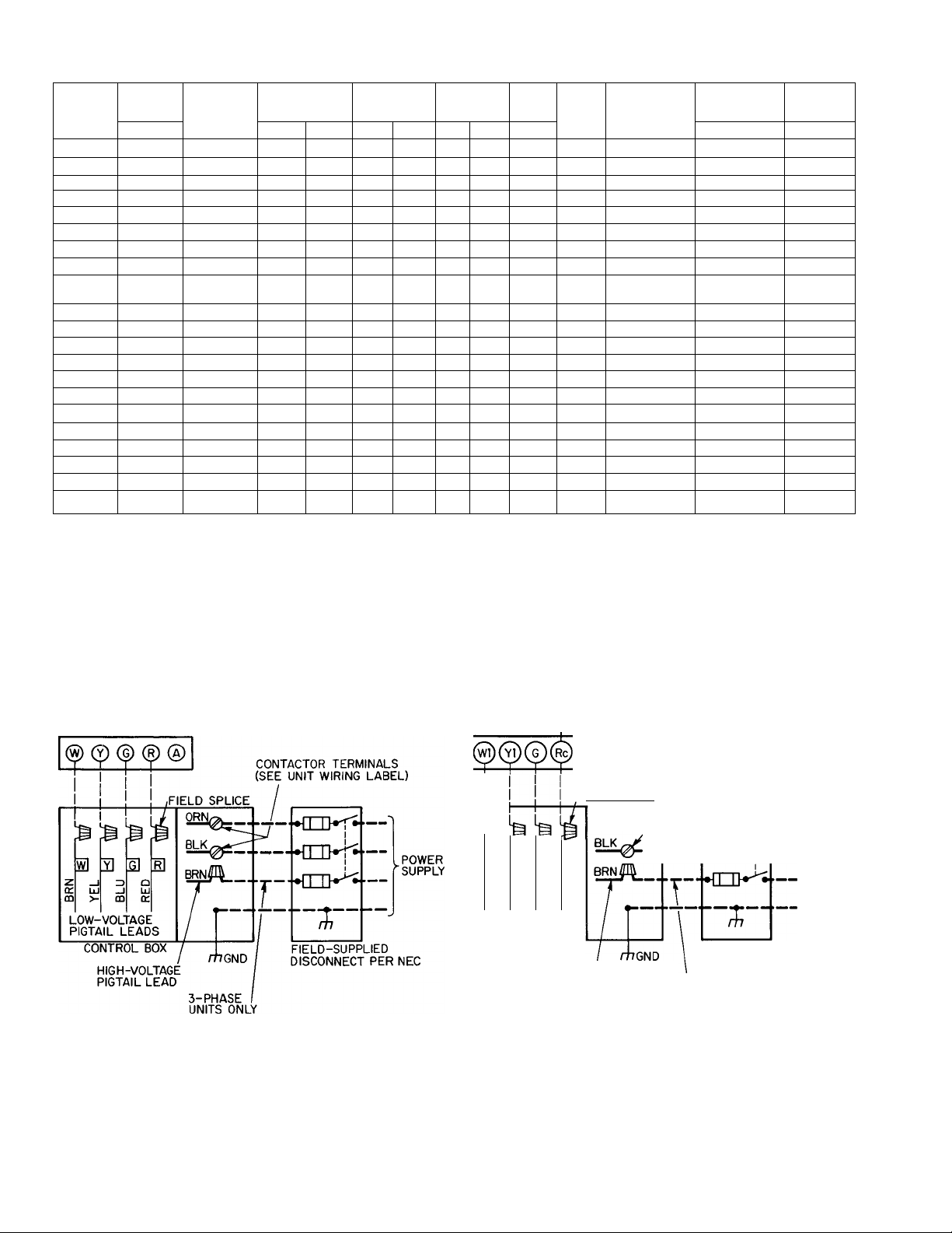
Table 3 — Electrical Data (60 Hz)
MODEL
48-
KLA118
KLA124
KHA024
KLA130
KHA030
KLA136
KLA036
KLA036
KHA136
KHA036
KHA036
KLA142
KLA042
KHA042
KHA042
KLA148
KLA048
KLA048
KHA048
KHA048
KLA1 60
KHA060
AWG — American Wire Gage
FLA — Full Load Amps
IFM — Indoor Fan Motor
LRA “ Locked Rotor Amps
MCA — Maximum Circuit Ampacity
OFM — Outdoor Fan Motor
RLA — Rated Load Amps
SERIES
310BE 208/230-1
310BE 208/230-1
310BF
310BE
310BF
310BE 208/230-1
510CE
610CE 460-3
310BE
310BF
510CE.CF
310BE
510CE
310BF
51 DCF 208/230-3
310BE
510CE
610CE 460-3
310BF 208/230-1
510CF
310BE
310BF
VOLTSPHASE
208/230-1
208/230-1
208/230-1
208/230-3
208/230-1
208/230-3
208/230-1
208/230-3
208/230-1
208/230-1
208/230-3 187
208/230-3
230-1
230-1
OPERATING
VOLTAGE*
Max
Min
197
197
197
197
197
197
187 253
414 506
197
187 253
197
187
197
187
197
414
197 253
187 253
207 253
207 253
253
253
253
253
253
253
253
253
253
253
253
253
253
506
COMPR FLA
RLA LRA
8 7
11 7 63 0 1 7
11 7 63 0
13 7 76.0
13.7 76 0
17 6 88 0 4 6
11 5 65 1
5 1 32 8
17 6 88 0 3 8
11.5 65.1 5.6
23.9 95.4 4.1
15 3
23.9 95.4
15.3 82.0 5.0 1.0 25.2
23.7 116.0 4.5 1.9 36.1
14 7 92 0 7 8 2 2
70
23 7
14 7
27 8 130 0 6 2
27 8 130 0
‘Voltage limits between which the unit will operate satisfactorily
flf other than 75 C copper wire is used, determine size from unit ampacity and the National
Electrical code Voltage drop of wire must be less than 2% of unit rated voltage Maximum
wire length is for one way along the wiie path from unit to service panel
^Maximum dual element size
IFM
49 0 1 2
3 0 1 0 18 7
3.1 1.0 21.2
2.9 1.0
4 7
1 9 0 6 8 9
82.0 5.6 1.0
3.9 0.8 34.6
46 0
3 3 1 2
116.0 3.7
5 8
92 0
6 5
MCAt
OFM
1 0 13 1 10 9 20 14
1 0 17 4 14 4 25 12
21.0 17.6 30
1 0 27 6
1 0 20 1 17 2 25
08 26 6
1.0 21.0
0.8 34.8
25.8 21.9 35 10
28 4 24 7 35
13 3 11 5 20 14
1.9
35.3 29.3 50 8 111
2.2 26.4
42 9
1 9
1.9
43 2 36 2 60 8 99
MAX
AMPS
15 7 25 12
17.8 30
23 2 40
22 2 40 10
18.1 25 10
28.8 50 8
28.6 50 8 114
21.3 35 10 111
30.1 50
22.7 35 10 104
35 9 60 8
MAX FUSE
SIZE (Amps)t
7.6 15 14 272
MIN WIRE
SIZE (AWG)t
(75C Copper)
10 115
10 116
10 88
10 137
8 108
10 96
MAX
WIRE
LENGTHt
76
89
82
92
130
113
108
180
100
SINGLE-STAGE HEAT 6 COOL-
MANUAL CHANGEOVER
, Field Low-Voltage Wiring
, Field High-Voltage Wiring
. Factory Low-Voltage Wiring
. Factory High-Voltage Wiring
Fig. 8 — High- and Low-Voltage Connections
SINGLE-STAGE HEAT 8 COOL-
AUTOCHANGEOVER
JUMPER-1
CONTACTOR TERMINALS
FIELD SPLICE^
G]
3
_J
>- CD
LOW-VOLTAGE
PIGTAIL LEADS
CONTROL BOX
NOTE: For manual changeover applications, use thermostat part no HH01AD042 with
subbase part no HH93AZ042; or thermostat part no HH01AD040 with subbase part no.
HH93AZ040
For automatic changeover, use thermostat part no HH07AT174 with subbase part no
HH93AZ096; or thermostat part no HH10AD041 with subbase part no HH93AZ041
o
3
LiJ
q:
HIGH-VOLTAGE
PIGTAIL LEAD
(SEE UNIT WIRING LABEL)
--------
—■
---------
♦OHM^ —
FIELD-SUPPLIED
DISCONNECT PER NEC
3-PHASE
UNITS ONLY
.POWER
SUPPLY
Loading...