


|
|
CONTROL PANEL |
|
3 1 9 V 2 1 E N |
|||
FOR 24 V GEARMOTORS |
|||
|
|
|
|
INSTALLATION MANUAL
ZL92
English EN

ENGLISH
WARNING!
Important instructions for the safety of people:
READ CAREFULLY!
Foreword
• Use of the products must be restricted to its intended use (i.e. that for which it was expressly built for). Any other use is to be considered dangerous. Came Cancelli Automatici S.p.A. is not liable for any damage resulting from improper, wrongful or unreasonable use • Keep these warnings with the installation and use manuals issued with the automated system.
Before installing
(preliminary check: in case of a negative outcome, do not proceed before having complied with the safety obligations)
• Make sure that the parts you intend to automate are in good working order, and that they are properly balanced and aligned. Also, make sure that proper mechanical stops are already in place • If the operator will be installed at a height of less than 2.5 m from the ground or other access level, check whether you will need any protections and/or warnings • Any gate leaves, fi tted with pedestrian entrances, onto which you will install an operator, must have a blocking mechanism when the gate is in motion • Make sure that the opening of the automated gate is not an entrapment hazard as regards any surrounding fi xed parts • Do not mount the operator upside down or onto any elements that may fold under its weight. If needed, add suitable reinforcements at the points where it is secured • Do not install onto gates on either an upward or downward slope (i.e. that are not on fl at, level ground) • Check that any lawn watering devices will not wet the gearmotor from the bottom up.
Installation
• Carefully section off the entire site to prevent unauthorised access, especially by minors and children • Be careful when handling operators that weigh more than 20 Kg (see installation manual). In such cases, employ proper weight handling safety equipment • All opening commands (e.g. buttons, key selectors, magnetic detectors, etc.) must be installed at least 1.85 m from the gate’s area of operation perimeter - or where they cannot be reached from the outside of the gate. Also, the direct commands (e.g. push button, or proximity devices, etc.) must be installed at a height of at least 1.5 m and must not be accessible to the public • All ‘maintained action’ commands, must be placed where the moving gate leaves, transit areas and driveways are completely visible • If missing, apply a permanent label that shows the position of the release mechanism • Before delivering to the client, verify that the system is EN 12453 (impact test) standard compliant. Make sure that the operator has been properly adjusted and that the safety and protection devices, as well as the manual release
are working properly • Where necessary and in plain sight, apply the Warning Sings (e.g. gate plate).
Special instructions and advice for users
•Keep the gate’s area of operation clean and clear of any obstacles. Trim any vegetation that may interfere with the photocells • Do not allow children to play with the fi xed command devices, or in the gate’s area of operation. Keep any remote control devices (i.e. transmitters) away from the children as well • Frequently check the system, to see whether any anomalies or signs of wear and tear appear on the moving parts, on the component parts, on the securing points, on the cables and any accessible connections. Keep any joints (i.e. hinges) lubricated and clean, and do the same where friction may occur (i.e. slide rails) • Perform functional tests on photocells and sensitive edges, every six months. Keep glass panels constantly clean (use a slightly water-moistened cloth; do not use solvents or any other chemical products) • If the system requires repairs or modifi cations, release the operator and do not use it until safety conditions have been restored
•Cut off the power supply before releasing the operator for manual openings. See instructions • Users are FORBIDDEN to carry out ANY ACTIONS THAT THEY HAVE NOT BEEN EXPRESSLY ASKED TO DO OR SO INDICATED in the manuals. Any repairs, modifi cations to the settings and extraordinary maintenance MUST BE DONE BY THE TECHNICAL ASSISTANCE STAFF • On the periodic maintenance log, note down the checks you have done.
Special instructions and advice for all
•Avoid working near the hinges or moving mechanical parts
•Stay clear of the gate’s area of operation when in motion • Do not resist the direction of movement of the gate; this may present a safety hazard • At all times be extremely careful about dangerous points that must be indicated by proper pictograms and/or black and yellow stripes • When using a selector or command in ‘maintained action’ mode, keep checking that there are no people in the area of operation of the moving parts. Do this until you release the command • The gate may move at any time without warning • Always cut the power when cleaning performing maintenance.
2 - Manual code: 319V21EN Vers. 3 04/2017 © CAME cancelli automatici S.p.A. - The data and information in this manual are subject to change at any time without prior notice required by Came Cancelli Automatici S.p.A.
P.
Legend of symbols
 This symbol shows which parts need to be read carefully.
This symbol shows which parts have to do with safety.

 This symbol shows what to tell end users.
Intended use and limitations of use
Intended use
The ZL92 control panel is engineered to command 24 V DC operators for swing gates of the STYLO, MYTO, FROG-J and AMICO series.  Any installation and use other than that explained in this manual are forbidden.
S.p.A. |
Limitations to use |
|||
Automatici |
||||
|
|
|
||
Follow all cable distance and diameter instructions as shown in the table “Cable type and section” |
||||
|
||||
Cancelli |
The overall power of the motors must not exceed 300 W. |
|||
|
|
|
||
|
|
|
||
Cameby |
Description |
|||
|
||||
required |
The control panel is powered by 230 V AC, with 50 / 60 Hz frequency. The command devices and accessories work on 24 V. War- |
|||
notice |
Engineered and manufactured entirely by CAME Cancelli Automatici S.p.A.. |
|||
ning! The accessories must not exceed 50 W overall. |
||||
|
||||
prior |
The transformers are fitted with a protection that keep the gate leafs open even when overheating. The leafs are closed only after |
|||
the temperature falls below overheating threshold. |
||||
without |
All connections are protected by quick fuses, see table. |
|||
|
||||
any time |
Functions on the input and output contacts, time adjustments and user management, are all handled via the display and managed |
|||
by the software. |
||||
It is set up to fit the LB90 card which provides power to the electrical board via emergency batteries, which are in turn automatically |
||||
at |
triggered during power outages. When the line current returns, it recharges the batteries. |
|||
are subject to change |
||||
Technical data |
||||
manual |
|
|
|
|
|
|
|
|
|
TECHNICAL DATA |
|
|
FUSE TABLE |
|
|||
in this |
|
|
|
|
||||
|
Power supply |
|
230 V - 50/60 Hz |
|
to protect: |
|
fuse rated to: |
|
information |
|
|
|
|
||||
Maximum rated power |
|
300 W |
|
|
|
|
||
|
|
Electronic line card |
|
3.15 A-F = 120 V |
||||
|
|
|
|
|||||
and |
Power draw when idle |
|
110 mA |
|
|
|
1.6 A-F = 230 V |
|
Maximum power for 24 V accessories |
|
50 W |
|
24 V accessories |
|
2°-F |
||
data |
|
|
|
|||||
Insulation class of the circuits |
|
II |
|
|
|
|
||
The |
|
|
Command device (control panel) |
|
1 A-F |
|||
|
|
|
|
|
|
|||
|
|
|
|
|
|
|||
- |
|
Container material |
|
ABS |
|
|
|
|
S.p.A. |
|
|
|
|
|
|
||
|
Motor 1 / Motor2 |
|
6.3 A = 250 V |
|||||
Container protection rating |
|
IP54 |
|
|
||||
cancelliautomatici |
|
|
|
|
|
|||
|
|
|
|
|
|
|
||
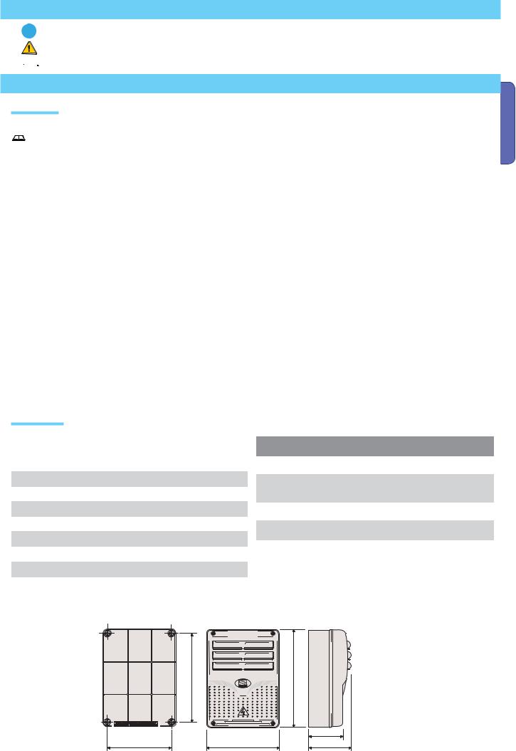
Dimensions |
|
-20 / +55°C |
|
|
|
|
||
|
Working temperature |
|
|
|
|
|
||
CAME |
|
|
|
|
|
|
|
|
(mm) |
|
|
|
|
|
|||
© |
|
|
|
|
|
|
|
|
319V21EN Vers. 3 04/2017 |
|
|
code: |
|
|
Manual- |
|
|
|
|
|
|
|
|
P. 3 |
|
|
ENGLISH

Main component parts
|
1 |
-Transformer |
|
|
|
|
|
|
|
|
2 |
-Card fuse |
|
1 |
|
|
|
|
|
|
3 |
-Accessories fuse |
|
|
|
|
|
|
|
|
4 |
-Display |
|
|
|
|
|
|
|
|
5 |
-Memory roll card connector |
|
|
|
|
|
|
|
ENGLISH |
6 |
-AF card connector |
|
17V |
230V |
|
|
|
|
8 -Lack of calibration warning LED |
|
|
|
|
|||||
|
7 |
-R700 or R800 card connector |
|
26V |
|
|
|
||
|
|
|
|
|
|
|
|||
|
indicator |
|
|
0 |
|
|
|
||
|
9 |
-Programming buttons |
|
0V |
|
|
|
|
|
|
|
|
|
|
|
|
|||
|
10 |
-Terminal boards |
|
|
|
|
|
|
|
|
11 -230 V power terminal boards |
|
|
|
|
|
3 |
||
|
12 |
-Line fuse |
|
|
|
|
|
17 |
|
|
13 |
-Current on-line warning LED indicator |
|
|
|
|
|||
|
|
|
|
|
|
||||
|
14 |
-Motor 1 fuse |
|
|
|
|
|
4 |
|
|
15 |
-Motor 2 fuse |
|
|
|
|
|
||
|
|
|
|
|
|
9 |
|||
|
16 |
-Antenna connection terminal board |
|
|
|
|
|||
|
|
|
|
|
|
||||
|
17 |
-Thermal terminal board |
14 |
|
|
|
|
8 |
|
|
|
|
|
15 |
|
|
|
|
|
|
|
|
|
2 |
|
|
|
|
|
|
|
|
|
|
|
|
|
|
6 |
|
|
|
|
12 |
|
|
|
|
|
|
|
|
|
11 |
|
|
|
|
16 |
|
|
|
|
|
|
|
|
|
|
|
|
|
|
|
|
10 |
13 |
5 |
7 |
Warning! Before doing any work on the control panel, make sure to cut off the main current or disconnect the batteries.
Installation
Installation must be done by qualified, expert staff and in full compliance with current laws and regulations.
Preliminary checks
Before installing, do the following:
•Check that the control panel is anchored to a solid surface which is protected from possible impacts, and that the nuts, bolts, wall plugs, etc., are suitable for the job.
•Make sure you have a suitable omnipolar cut-off device with contacts more than 3 mm apart, and independent (sectioned off) power supply.
• Make sure that any connections inside the box (that provide continuance to the protective circuit) are fitted with extra insulation as compared to the other conductive parts inside.
•Set up proper pipes and conduits for electrical cables to pass through, making sure these are protected from mechanical damage.
P. 4 - Manual code: 319V21EN Vers. 3 04/2017 © CAME cancelli automatici S.p.A. - The data and information in this manual are subject to change at any time without prior notice required by Came Cancelli Automatici S.p.A.
P. 5 - Manual code: 319V21EN Vers. 3 04/2017 © CAME cancelli automatici S.p.A. - The data and information in this manual are subject to change at any time without prior notice required by Came Cancelli Automatici S.p.A.
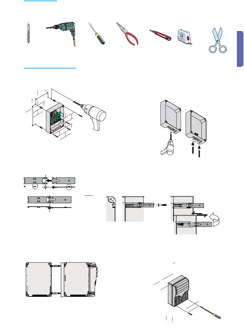
Tools and equipment
Make sure you have all of the tools and materials you will need to proceed with the installation in total safety, according to current rules and regulations.
Here are some examples.
ENGLISH
Anchoring and mounting the box
1) Secure the base of the panel to a protected area; we suggest using cross slot Phillips head bolts of max. 6 mm in diameter.
2) Perforate the pre-punched holes and insert the cable glands with the corrugated tubing for the electrical cables to travel through.
N.B.: diameter of the pre-punched holes: 20 mm.
|
3) Assemble the pressure hinges.
 !!
!!
4) Insert the hinges into the box (either on the right or left side, as you prefer) and secure them using the supplied nuts and bolts.
Slide the hinges so they can rotate.
15 mm~
|
|
|
|
|
|
|
|
|
|
|
|
|
|
|
|
|
|
|
|
|
|
|
|
|
|
|
|
|
|
|
|
|
|
|
|
|
|
|
|
5) Snap the hinge covers into place. |
|
|
6) After any calibrations and adjustments, secure the |
||||||||||||||||
|
|
|
|
|
|
|
|
|
|
cover using the supplied screws. |
|||||||||
|
|
|
|
|
|
|
|
|
|
|
|
|
|
|
|
|
|
|
|
|
|
|
|
|
|
|
|
|
|
|
|
|
|
|
|
|
|
|
|
|
|
|
|
|
|
|
|
|
|
|
|
|
|
|
|
|
|
|
|
|
|
|
|
|
|
|
|
|
|
|
|
|
|
|
|
|
|
|
|
|
|
|
|
|
|
|
|
|
|
|
|
|
|
|
|
|
|
|
|
|
|
|
|
|
|
|
|
|
|
|
|
|
|
|
|
|
|
|
|
|
|
|
|
|
|
|
|
|
|
|
|
|
|
|
|
|
|
|
|
|
|
|
|
|
|
|
|
|
|
|
|
|
|
|
|
|
|
|
|
|
|
|
|
|
|
|
|
|
|
|
|
|
|
|
|
|
|
|
|
|
|
|
|
|
|
|
|
|
|
|
|
|
|
|
|
|
|
|
|
|
|
|
|
|
|
|
|
|
|
|
|
|
|
|
|
|
|
|
|
|
|
|
|
|
|
|
|
|
|
|
|
|
|
|
|
|
|
|
|
|
|
|
|
|
|
|
|
|
|
|
|
|
|
|
|
|
|
|
|
|
|
|
|
|
|
|
|
|
|
|
|
|
|
|
|
|
|
|
|
|
|
|
|
|
|
|
|
|
|
|
|
|
|
|
|
|
|
|
|
|
|
|
|
|
|
|
|
|
|
|
|
|
|
|
|
|
|
|
|
|
|
|
|
|
|
|
|
|
|
|
|
|
|
|
|
|
|
|
|
|
|
|
|
|
|
|
|
|
|
|
|
|
|
|
|
|
|
|
|
|
|
|
|
|
|
|
|
|
|
|
|
|
|
|
|
|
|
|
|
Electrical connections
Cable types and sections
ENGLISH
Connections |
Type of cable |
Length of cable |
Length of cable |
Length of cable |
|
1 < 10 m |
10 < 20 m |
20 < 30 m |
|||
|
|
||||
Control panel power supply |
|
3G x 1,5 mm2 |
3G x 1,5 mm2 |
3G x 2,5 mm2 |
|
Power supply to motor* with encoder |
|
3G x 1,5 mm2 |
3G x 1,5 mm2 |
3G x 2,5 mm2 |
|
Power supply to motor**with encoder |
FROR CEI |
4G x 1,5 mm2 |
4G x 1,5 mm2 |
4G x 2,5 mm2 |
|
Flashing light |
2 x 1,5 mm2 |
2 x 1,5 mm2 |
2 x 1,5 mm2 |
||
20-22 |
|||||
Photocell transmitters |
CEI EN |
2 x 0,5 mm2 |
2 x 0.5 mm2 |
2 x 0,5 mm2 |
|
|
50267-2-1 |
|
|
|
|
Photocell receivers |
4 x 0,5 mm2 |
4 x 0,5 mm2 |
4 x 0,5 mm2 |
||
|
|||||
Power supply to accessories |
|
2 x 0,5 mm2 |
2 x 0,5 mm2 |
2 x 1 mm2 |
|
Command and safety devices |
|
2 x 0,5 mm2 |
2 x 0,5 mm2 |
2 x 0,5 mm2 |
|
Antenna connection |
RG58 |
|
Maximum 10 m |
|
|
|
|
|
|
|
* MYTO ME - FROG J - AMICO - STYLO RME / ** STYLO ME
N.B.: If the cable length differs from that specified in the table, then you must determine the proper cable diameter based on the actual power draw from the connected devices and according to the CEI EN 60204-1 standards.
For connections that require several, sequential loads, the sizes given on the table must be re-evaluated based on actual power draw and distances.
When connecting products that are not specified in this manual, please follow the documentation provided with said products.
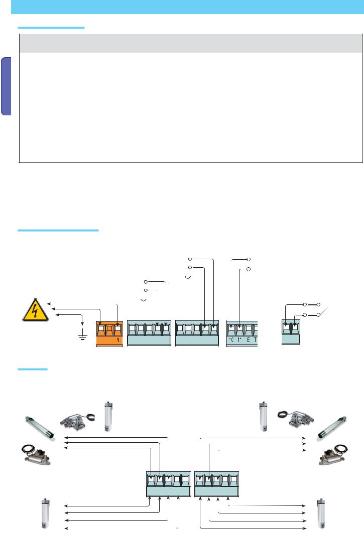
Power source and accessories
|
|
|
|
|
|
|
|
|
|
Terminals for powering the following |
12 V – 15 W maximum, Electro-lock for the |
|
|
|
|
accessories: |
|||||
|
||||||||||
Myto, Frog-J, Amico and Stylo RME motors |
|
|
|
|
|
- 24 V AC, DC Overall power allowed: |
||||
|
|
|
|
|
|
|
|
|
|
50 W |
Possible second 12 V – 1 W max. electrolock |
|
|
|
|
|
|
|
|
Possible output of the radio receiver’s |
|
|
|
|
|
|
|
|
|
|||
for the Myto, Frog-J, Amico and Stylo RME |
|
|
|
|
|
|
second channel (N.O. socket). |
|||
motors |
|
|
|
|
|
|
|
|
|
Max. socket rating: 500 mA – 24 V DC. |
|
|
|
|
|
|
|
|
+ - |
||
|
||||||||||
Power supply 230 |
|
|
|
|
|
|
V AC |
L |
M1 N1 ENC1 EB1 V1 |
M2 N2 ENC2 EB2 V2 |
" |
" |
|
frequency 50/60 Hz |
||||||
|
|
|
|
|||
Gearmotor |
|
|
|
|
|
M1 – 24 V DC gearmotor featuring delayed action on opening
MYTO ME
STYLO RME
AMICO
M2 - 24V DC gearmotor featuring delayed action on closing
MYTO ME
STYLO RME
AMICO
FROG-J |
FROG-J |
M1 N1 ENC1 EB1 V1 |
M2 N2 ENC2 EB2 V2 |
STYLO ME |
STYLO ME |
6 - Manual code: 319V21EN Vers. 3 04/2017 © CAME cancelli automatici S.p.A. - The data and information in this manual are subject to change at any time without prior notice required by Came Cancelli Automatici S.p.A.
P.
P. 7 - Manual code: 319V21EN Vers. 3 04/2017 © CAME cancelli automatici S.p.A. - The data and information in this manual are subject to change at any time without prior notice required by Came Cancelli Automatici S.p.A.
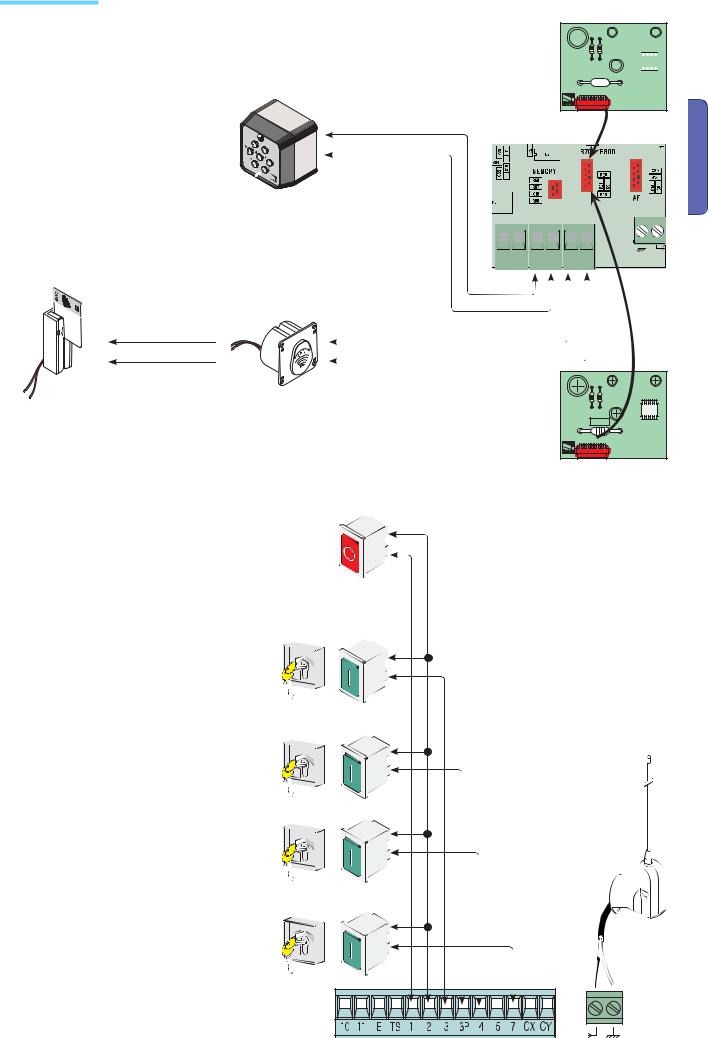
Command devices
|
N.B. : insert the (R800) |
|
|
|
|
|
|
|
|
|
|
|
|
|
|
|
|
|
|
decoder card to have |
|
|
|
|
|
|
|
|
|
|
|
|
|
|
|
||
|
|
|
|
|||||||||||||||
|
the (S7000) keypad |
|
|
|
|
|
|
|
||||||||||
001S7000 – Keypad selector |
selector recognised. |
|
|
|
|
|
|
|
|
|
|
|
|
|
||||
|
|
|
|
|
|
|
|
|
|
|
|
|
||||||
|
|
|
|
|
|
|
|
|
|
|
|
|
||||||
|
|
|
|
|
|
|
|
|
|
|
|
|
||||||
R800
ENGLISH
001LT001 - Magnetic card reader |
A B S1 GND |
|
|
|
001TSP00 - Transponder sensor |
|
Red |
|
Black |
|
CAME |
|
N.B. : insert the (R700) decoder |
|
card to have the (TSP00) sensor or |
|
(LT001) card reader recognised. |
R700
Stop button (N.C. contact) - Button to stop gate while excluding the automatic closing cycle. For movement to resume you must press the command button or transmitter button.
N.B.: if the contact is unused, select “0” = (Disabled) from the F1 functions menu.
Key selector and/or opening button (N.O. contact) - Gate opening command.
Key selector and/or partial opening button (N.O. contact) - Partial gate opening for pedestrian access.
Key selector and/or closing button (N.O. contact) - Gate closing command.
Key selector and/or commands button (N.O. contact) - Commands for opening and closing the gate – pressing the button or turning the key-switch, inverts the gate’s movement or stops it depending on how it is set on the 2-7 command in the “FUNCTIONS” menu.
Antenna with RG58 cable for the remote control.
ENGLISH
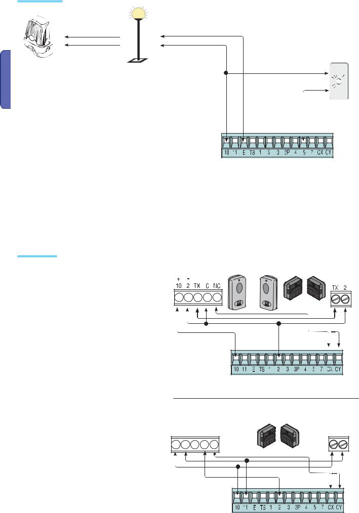
Warning devices |
|
|
|
|
|
|
|
|
|
Open gate indicator-light (So- |
|
||
|
|
|
cket rating: 24 V – 3 W max.). It |
|
||
|
|
|
turns on when the gate is open. |
|
||
|
|
|
It turns off when the gate is |
|
||
|
|
|
closed (see function “F10”). |
|
||
Flashing light (socket |
Courtesy or cycle light (contact rated up to: |
|
|
|
|
|
rating: 24 V DC - 25 W |
24V – 25 W max.) – auxiliary connection of |
|
|
|
|
|
max.) – It flashes during |
an outdoor lamp that can be freely positio- |
|
|
|
|
|
opening and closing |
ned, for additional lighting of the driveway. |
|
|
|
|
|
phases of leaf. |
Cycle light: It stays on from the moment the |
|
|
|
S.p.A. |
|
|
gate begins opening until it is fully closed |
|
|
|
||
|
|
|
|
|
||
|
(including the automatic closing time). |
|
|
|
Automatici |
|
|
period (see function “F25”). |
|
|
|
|
|
|
Courtesy light: Stays on for a fixed time |
|
|
|
|
|
Safety devices |
|
|
|
|
|
at any time without prior notice required by Came Cancelli |
|
RX |
photocells |
photocells |
TX |
changeto |
|
|
|
|||||
|
|
|
DIR |
DELTA-S |
|
subject |
12978 compliant safety devices such as photocells. |
|
|
|
|
||
Confi gure either (N.C.) contacts CX or CY , input for EN |
|
|
|
|
|
|
See CX (F2 Function) or CY(F3 Function) input functions |
|
|
|
|
are |
|
|
|
|
|
manual |
||
in: |
|
|
|
|
|
|
|
|
|
|
|
|
|
- C1 «re-open during closing phase», when the gate |
|
|
|
|
this |
|
leaf is closing, opening the contact triggers the inver- |
|
|
|
|
||
|
|
|
|
in |
||
sion of the direction of movement until the gate leaf is |
|
|
|
|
||
|
|
|
|
information |
||
fully open. |
|
|
|
|
|
|
|
|
|
|
|
|
|
- C2 «re-close during opening phase», when the gate |
|
|
|
|
|
|
leaf is opening, if the contact is opened it triggers an |
|
|
|
|
and |
|
inversion of the direction until gate leaf is fully closed; |
|
|
|
|
||
|
|
|
|
data |
||
- C3 «partial stop», halts moving gate leaves and |
|
|
|
|
||
|
|
|
|
- The |
||
causes them to automatically close (if this functions has |
|
|
|
|
||
|
|
|
|
S.p.A. |
||
been selected); |
|
|
|
|
|
|
- C4 «stand-by obstacle», stops the moving gate leaves |
|
|
|
|
automatici |
|
removed. |
|
|
|
|
|
|
causing them to start moving again once obstacle is |
|
|
|
|
cancelli |
|
to be deactivated during programming. |
RX |
photocells |
|
TX |
||
N.B. : if CX and CY contacts are unused they need |
|
DELTA |
|
|
|
|
|
|
./ # .# |
|
|
|
CAME |
|
|
|
|
|
|
8 - Manual code: 319V21EN Vers. 3 04/2017 © |
P.
P. 9 - Manual code: 319V21EN Vers. 3 04/2017 © CAME cancelli automatici S.p.A. - The data and information in this manual are subject to change at any time without prior notice required by Came Cancelli Automatici S.p.A.
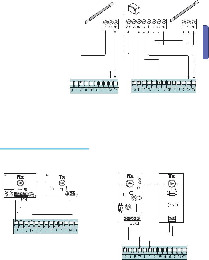
Confi gure either (N.C.) contacts CX or CY, input for safety devices such as sensate edges, that comply with
EN 12978 standards. See CX (F2 Function) or CY(F3 Function) input functions in:
-C7 «re-open while closing», during gate closing, opening the contact causes inversion of movement until gate is fully open;
-C8 «re-close while opening», during gate opening, opening the contact causes inversion of movement until gate is fully close.
N.B. : if CX and CY contacts are unused they need to be deactivated during programming.
DF with monitoring card for DFI connections.
ENGLISH |
Electrical connection for running the photocells safety test
DOC / DELTA
|
|
|
|
|
|
. / |
# |
. # |
|
DIR / DELTA S |
|
|
||
|
|
|
|
&53)"),% M! |
|
|
# .# |
|
|
|
48 |
4848 |
|
|
|
|
|
|
|
At each opening and closing command, the control board assesses the efficiency status of the safety devices (photocells). Any anomaly found is signaled with the fl ashing of the LED on the control board. Consequently it cancels any commands coming from the transmitter or the button.
Electrical connection to enable the photocell safety test:
-the transmitter and the receiver, must be connected as per the diagram;
-from the “F5” function select which inputs to run the safety test on.
 Loading...