


|
|
|
CONTROL PANEL |
|
|
|
|
|
319T90EN |
|
FOR 230 V - 400 V GEARMOTORS |
|
|
|
|
INSTALLATION MANUAL
ZT6 - ZT6C
English EN
"IMPORTANT INSTALLATION SAFETY INSTRUCTIONS"
“WARNING: IMPROPER INSTALLATION MAY RESULT IN SERIOUS HARM. PLEASE FOLLOW ALL INSTALLATION INSTRUCTIONS” “THIS MANUAL IS INTENDED ONLY FOR PROFESSIONAL INSTALLERS OR OTHER COMPETENT INDIVIDUALS”
1 Legend of symbols
This symbol shows parts which must be read with care.
ENGLISH |
This symbol means the parts which describe safety issues. |
|
|
|
This symbol tells you what to tell the end-user. |
2 Intended use and limits to use
2.1 Intended use
The ZT6 - ZT6C control panel is engineered by Came Cancelli Automatici S.p.A. for commanding 001BK-2200T sliding gates as well as 001C-BXT sectional, sliding and folding door operators.
Any installation and use other than that specified in this manual is forbidden.
2.2 Limitations to use
The overall power of the gearmotor when connected must not exceed 780 W.
3 Reference standards
Came Cancelli Automatici employs an ISO 9001 certified quality management system and an ISO 14001 environmental management system. Came only engineers and manufactures in Italy.
This product is compliant with: see statement of compliance.
4 Description
Single and tri-phase 230 V AC or 400 V AC tri-phase power supply. The control panel is protected by a 8 A fuse, while the low voltage accessories (24 V) are protected by a 2 A fuse.
The ZT6C control panel comes with safety block and 3-hard wired buttons (stop, open, close) on the case cover.
Warning! The overall power of the 24 V accessories must not exceed 20 W.
The card provides and controls the following features:
-automatic closing;
-partial opening for pedestrian passage;
-obstacle detections when gate is not moving at any point;
-maintained action;
-Pre flashing by the flashing light;
-Running the safety test feature.
The available command modes are:
-opening/closing;
-opening/closing with maintained action;
-open-stop-close-stop;
-Partial opening;
-total stop.
The photocells, after detecting an obstacle, may trigger:
-the reopening of the closing gate;
-the reclosing of the opening gate;
-a partial stop;
-a total stop.
Specific trimmers regulate:
-the working time for automatic closing;
-the partial opening time.
You can also connect:
-a courtesy lamp to light up the driving area for a set time;
-a lamp to light up the driving area during the open/close cycles.
TECHNICAL DATA
Power supply |
230 V / 400 V - 60 Hz |
|
|
Maximum power rating |
780 W |
|
|
Power draw when idle |
50 mA |
|
|
Maximum power for 24 V |
45 W |
accessories |
|
Maximum power for 230 V |
85 W |
accessories |
|
|
|
Circuit insulation class |
|
|
|
Container material |
ABS |
|
|
Protection rating of the container |
IP54 |
|
|
Working temperature |
- 20 / +55°C |
|
|
FUSE TABLE
to protect: |
fuses for: |
|
|
Electronic board (line) |
A 8 |
|
|
Accessories |
A 2 |
|
|
Command devices (control unit) |
A 630 |
|
|
2 - Manual code: 319T90 ver. 3 04/2014 © CAME Cancelli Automatici S.p.A. - The data and information in this manual may be changed at any time and without obligation on the part of Came Cancelli Automatici S.p.A. to notify said changes.
p.

3 - Manual code: 319T90 ver. 3 04/2014 © CAME Cancelli Automatici S.p.A. - The data and information in this manual may be changed at any time and without obligation on the part of Came Cancelli Automatici S.p.A. to notify said changes.
4.1 Dimensions
ZTC overall dimensions |
|
|
ZT6C case overall dimensions |
|||
|
|
|
|
|
|
|
|
|
|
|
|
|
|
|
|
|
|
|
|
|
320 |
320 |
ENGLISH |
#!-% |
|
#!-% |
!02% #()5$% 
240 |
240 |
240 |
165 |
4.2 Main components
1. |
Dip-switch selecting features |
7. |
Radio code notification LED light |
2. |
Control panel fuse 630mA F |
8. |
Connecting terminals |
3. |
Accessories fuse 2 A F |
9. |
Transformer connection terminals |
4. |
Line fuse 8 A F |
10. |
Buttons to memorise radio code |
5. |
AF radio frequency card socket |
11. |
Trimmer TCA: adjusting automatic closing time |
6. |
Power supply LED-signal light |
12. |
PART. OPEN TRIMMER.: adjusting open-partially |
9 |
6 |
3 |
2 |
11 |
12
7
1
4
5
10
8
 Warning! Before acting on the device, cut off the main power supply.
Just operate the safety block on the ZT6C.
p.
5 Installation
|
|
5.1 Preliminary checks |
|
|
|
Before beginning to install, the following is necessary: |
|
|
• Make sure that the point where the electrical panel is anchored is free from any impacts, and that the surface is solid and that |
||
|
proper tools and materials are used (i.e. screws, wall plugs, etc.). |
||
|
• Set up a suitable omni polar cut-off device, with distances greater than 3 mm between contacts, with sectioned power source. |
||
ENGLISH |
• |
Check that any connections inside the container (made for continuity purposes of the protective circuit) are fitted with extra |
|
insulation compared to other internal conductive parts. |
|||
|
|||
|
• Set up proper conduits and electric cable raceways, making sure these are protected from any mechanical damage. |
||
|
|
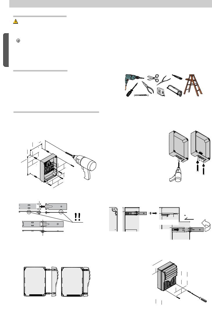
5.2 Tools and equipment |
|
|
Make sure you have all the tools and materials needed to carry |
||
|
out the installation in total safety and in accordance with current |
||
|
regulations. Here are some examples. |
||
5.3Fastening and mounting the container
1)Secure the base of the panel in a safe area; yes max. 6 mm 2) Perforate the pre-punched holes and insert the cable glands
Head with to.
|
with corrugated tubes for the electrical cables to run through.
N.B.: the pre-punched holes have 20 mm diameter.
Careful not to damage the electronic board inside the panel!
|
|
|
|
|
|
4) insert the hinges into the housing (either left or right) and secure |
|||||
Assemble the pressure hinges. |
them using the issued screws and washers. |
||||||||||
|
|
|
|
|
|
|
|
|
|
|
|
|
|
|
|
|
|
|
|
|
|
|
|
|
|
|
|
|
|
|
|
|
|
|
|


 15 mm ~ the slide to rotate
5) Snap the cover onto the hinges. |
|
|
|
|
|
|
|
|
|
|
|
|
|
|
|
|
|
|
|
|
|
6) After adjusting and setting, secure the cover using the issued |
||||||||||
|
screws. |
|
|
|
|
|
|
|
||
|
|
|
|
|
|
|
|
|||
|
|
|
|
|
|
|
|
|
|
|
|
|
|
|
|
|
|
|
|
|
|
4 - Manual code: 319T90 ver. 3 04/2014 © CAME Cancelli Automatici S.p.A. - The data and information in this manual may be changed at any time and without obligation on the part of Came Cancelli Automatici S.p.A. to notify said changes.
p.
 Loading...