


G4000
Documentazione
Tecnica
25
rev. 6.1
01/2003
©
CAME
CANCELLI
AUTOMATICI
119G25
SERIE GARD |
GARD
SERIES
|
SÉRIE GARD |
BAUREIHE
GARD
|
SERIE GARD
G4000 / G4001
CANCELLI AUTOMATICI
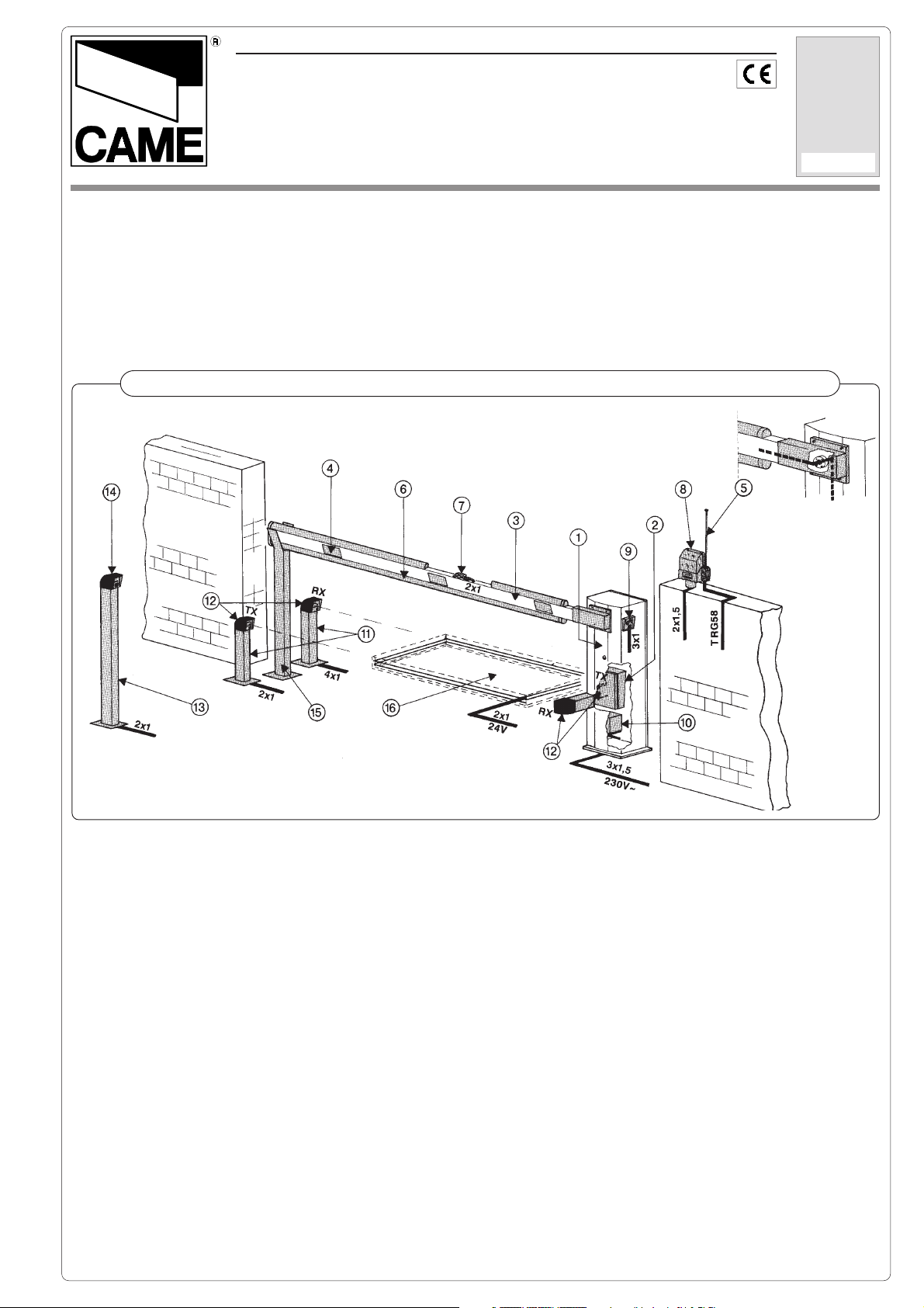
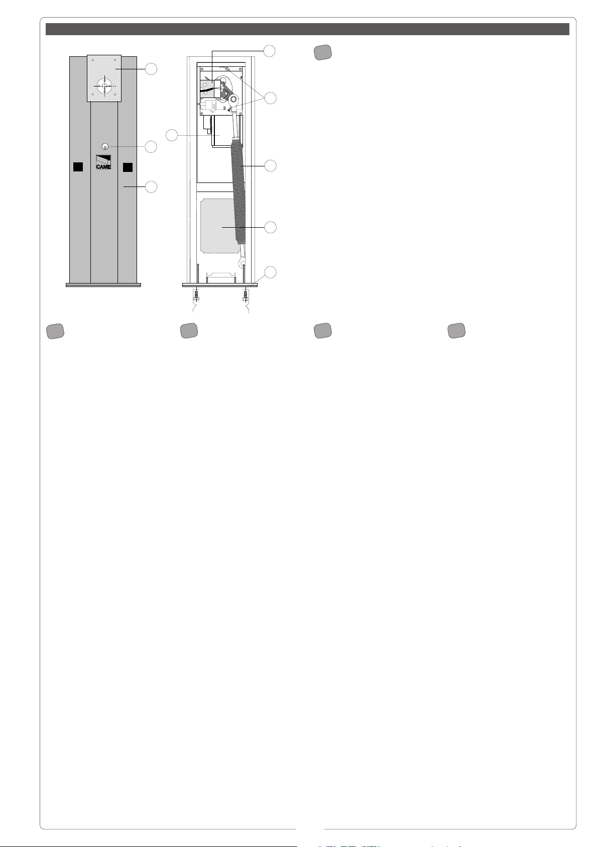
1. Gruppo GARD
2. Quadro comando
Accessori
3. Asta in alluminio
4. Strisce rosse
fosforescenti
5. Antenna
6. Gomma protettiva
7. Lampade di segnala-
zione
8. Lampeggiatore di
movimento
9. Selettore a chiave
10. Batteria di emergenza
11. Colonnina per
fotocellule
12. Fotocellule di sicurez-
za
13. Colonnina per lettore
magnetico
14. Lettore magnetico
15. Appoggio fisso
16. Sensore magnetico
1. GARD unit
2. Control panel
Accessories
3. Aluminum barrier
4. Red phosphorescent
strips
5. Antenna
6. Anti-collision rubber
7. Movement indicator
lights
8. Flashing movement
warrning light
9. Key-operated selector
switch
10. Emergency battery
11. Photocell Column
12. Safety photocells
13. Column for magnetic
card reader
14. Magnetic card reader
15. Fixed barrier support
16. Magnetic sensor
1. Groupe GARD
2. Armoire de
commande
Accessoires
3. Lisse en aluminium
4. Bandes rouges
phosphorescentes
5. Antenne
6. Boudin caoutchouc
anti-choc
7. Lampe de mouvement
8. Clignotant de
mouvement
9. Sélecteur à clé
10. Batterie d'urgence
11. Colonnette pour
photocellule
12. Photocellule de
sècuritè
13. Colonnette pour
lecteur de carta
magnétique
14. Lecteur de carte
magnétique
15. Appui fixe
16. Capteur magnétique
1. GARD- Bausatz
2. Steuerung Zubehör
3. Aluminium-Stange
4. Rote Phosphoreszenz-
Streifen
5. Antenne
6. Gummi Stoßschutz
7. Bewegungs-
Meldeleuchte
8. Blinkleuchte
9. Schlüsselschalter
10. Notbatterie
11. Photozellen-Säule
12. Sicherheits-Photozelle
13. Magnetkartenleser-
Säule
14. Magnetkartenleser
15. Feste Stütze
16. Magnetischer Sensor
1. Grupo GARD
2. Cuadro de mando
Accesorios
3. Barra de aluminio
4. Bandas roias
fosforescentes
5. Antena
6. Protector de goma
7. Làmpara de
movimiento
8. Làmpara intermitente
de movimiento
9. Selector con Ilave
10. Baterìa de urgencia
11. Columna para
fotocélula
12. Fotocélula de
seguridad
13. Columna para lector
magnético
14. Lector magnético
15. Apoyo fijo
16. Sensor magnético
Automazioni per barriere stradali veloci
Automation systems for swift road barriers
Automatisations pour barrières routieres rapides
Antriebe für Schnell-Schranken
Automatización para barreras viales rápidas
Impianto tipo -
Standard installation -
Installation type
- Standard Montage -
Instalaciòn tipo
2
Modelli:
G4000
Barriera con motoriduttore irreversibile
alimentato a 24V d.c., armadio in accia-
io zincato e verniciato, quadro di con-
trollo e comando interno.
G4001
Versione con armadio in acciaio inox.
Descrizione:
- Barriera motorizzata adatta alla sele-
zione di ingressi con passaggio utile fino
a 4 m. (con accessori fino a 3.5 m., vedi
pag. 7).
- Progettato e costruito interamente dal-
la CAME S.p.A., risponde alle vigenti
norme di sicurezza, con grado di prote-
zione IP 54.
- Garantito 24 mesi salvo manomissioni.
Accessori di completamento:
G0401
Asta in alluminio verniciato bianco se-
zione 60x40 mm, L = 4200 mm.
In alternativa
(per zone soggette a forte vento):
G0402 + G0405
Asta in alluminio tubolare verniciato
bianco sezione Ø 60 mm, L = 4200 mm.
+ attacco speciale per asta.
Attenzione! Controllate che le apparecchiature di comando, di sicurezza e gli accessori siano originali CAME; ciò garantisce e rende
l'impianto di facile esecuzione e manutenzione.
G0403
Gomma protettiva antiurto rossa completa di tappi per
asta G0401.
G0460
Confezione di lampade di segnalazione a 24V con
supporti per aste G0401 e scheda di intermittenza.
G0461
Confezione striscie rosso fosforescente per aste.
G0462
Appoggio fisso per aste.
G0463
Appoggio mobile per aste.
G0465
Rastrelliera in alluminio verniciata per aste.
G0467
Snodo per G0401.
G0468
Supporto per l'applicazione della fotocellula su armadio.
G0469
Supporto per l'applicazione del lampeggiatore su
armadio.
ACCESSORI OPZIONALIACCESSORI OPZIONALI
ACCESSORI OPZIONALIACCESSORI OPZIONALI
ACCESSORI OPZIONALI
Models:
G4000
Barrier with non-reversible, 24 V d.c.
gear motor, case in galvanised steel with
enamel finish, control panel and internal
drive system.
G4001
Version with stainless steel case.
Description:
- This unit can be used to control
entrances up to 4 meters wide (with
accessories up to 3,5 metres, see table
on page 7).
- Designed and constructed entirely by
CAME in compliance with current safety
standards, and with an IP 54 protecting
rating.
- Guaranteed for 24 months, unless
tampered with by unauthorized
personnel.
Optional accessories:
G0401
Cross-section 60x40 mm, L = 4200 mm.
aluminium barrier with white enamel
finish.
Alternative system
(for areas subject tstrong winds)
G0402 + G0405
Cross-section Ø 60 mm, L = 4200 mm
tubolar aluminium barrier with white
enamel finish + special attachment for
barrier rod.
Attention! to insure easy installation and conformance with current safety norms, we raccomend installation of CAME safety and
control accessories.
G0403
Red anti-collision bumper, complete with endcaps, for
G0401 barrier.
G0460
Package of 6 24V signal lamps complete of supports for
G0401 barriers, with flash-control circuit board.
G0461
Red phosphorescent strip for barriers.
G0462
Non-moving support for barriers.
G0463
Moving support for barriers.
G0465
White enameled aluminum fencing for barriers.
G0467
Joint for G0401 barrier.
G0468
Support for attachment of photocell to casings.
G0469
Support for attachment of flashing beacon to casings.
OPTIONAL ACCESSORIES
General specifications
ENGLISH
Caratteristiche generali
ITALIANO
3
Modèles:
G4000
Barrière avec motoréducteur irréversible
alimenté en 24 V d.c., armoire en acier
galvanisé et verni, tableau de contrôle
ou commande interne.
G4001
Version avec armoire en acier inox.
Description:
- Le groupe est indiqué pour le contrôle
des entrées avec passages jusqu à 4
m (avec accessoires jusqu’à 3,5 m., voir
tableau p. 7).
- Il a été entièrement concu et construit
par la Société CAME, conformément
aux normes de sécurité en vigueur avec
degré de protection IP 54.
- Il est garanti 24 mois sauf en cas
d'altérations.
Accessoires complémentaires:
G0401
Lisse en aluminium verni blanc section
60x40 mm, L = 4200 mm.
En alternative
(pour les zones sujettes à des vents
forts).
G0402 + G0405
Lisse en aluminium tubulaire verni blanc
section Ø 60 mm, L = 4200 mm. +
fixation spéciale pour lisse.
Attention ! Vérifiez que l’appareillage de commande, de sécurité et les accessoires sont des produits originaux CAME afin de garantir
l’installation et d’en faciliter le montage et l’entretien.
G0403
Coutchouc de protection antichoc rouge comprenant
bouchons pour lisse G0401.
G0460
Ensemble de 6 lampes de signalisation de 24V avec
supports pour lisses G0401 et carte de intermittencie.
G0461
Bande rouge phosphorescente pour lisses.
G0462
Appui fixe pour lisses.
G0463
Appui mobile pour lisses.
G0465
Tablier en aluminium verni pour lisses.
G0467
Articulation pour G0401.
G0468
Support pour l'application d'une photocellule sur
l'armoire.
G0469
Support pour l'application du clignotant sur l'armoire.
ACCESSOIRES EN OPTION
Modelle:
G4000
Schranke mit selbsthemmendem 24 V-
Gleichstrom-Getriebemotor, Gehäuse
aus verzinktem und lackiertem Stahl,
eingebaute Motorsteuerung.
G4001
Ausführung mit Edelstahl-Gehäuse.
Beschreibung:
-Die gruppe ist zum Antrieb von
Schranken mit Durchfahrtsbreiten bis 4
m. geeignet (mit Zubehör bis 3,5 m,
siehe Tabelle auf Seite 7).
- Vollkommen von der CAME S.p.A. den
geltenden Sicherheitsnormen
entsprechend entwickelt und hergestellt.
Schutzklasse IP 54.
- Garantie: 24 Monate, vorbehaltlich
unsachgemäßer Handhabung und
Montage.
Zubehör:
G0401
Aluminiumsstange, weiß lacktiert,
Schnitt 60x40 mm, L = 4200 mm.
als Alternative
(für Gebiete mit starkem Wind):
G0402 + G0405
Aluminiumrohr-Stange, weiß lacktiert
Schnitt Ø 60 mm, L = 4200 mm +
spezieller Schrankenbaumträger.
Achtung! Wir empfehlen original CAME-Schalt- und -Sicherheitsvorrichtungen mit entsprechendem Zubehör zu montieren, um die
einwandfreie Montage und die problemlose Wartung der Anlage zu gewährleisten.
G0403
Roter Gummi-Stoßschutz mit Stöpsel für Stange G0401
G0460
6-Stück-Packung 24V - Warnlampen mit Sockel für
Schranken G0401 und Blinksystemplatine.
G0461
Roter Phosphoreszenz-Streifen für Stange.
G0462
Feste Stütze.
G0463
Bewegliche Stütze.
G0465
Aluminium-Schrankengitter, weiß acktiert.
G0467
Gelenkstück für G0401.
G0468
Photozellenmontagehalter für Schranken.
G0469
Blinkleuchtenmontagehalter für Schranken.
ZUBEHÖR AUF ANFRAGE
Caractéristiques généralés
FRANÇAIS
Allgemeine merkmale
DEUTSCH
4
Modelos:
G4000
Barrera con motorreductor irreversible
alimentado a 24V d.c., armario de ace-
ro galvanizado y barnizado, cuadro de
control y mando interno.
G4001
Versión con armario de acero inox.
Descripción:
- El grupo es adecuado para la
selección de entradas con pasos de
hasta 6,5 m (con accesorios hasta 6 m,
ver tabla a pág 7).
- Diseñado y fabricado enteramente por
CAME S.p.A., cumple con las normas
de seguridad vigentes, con grado de
protección IP54.
- Garantizado 24 meses, salvo
manipulaciones.
Accesorios que lo completan:
G0401
Barra de aluminio barnizado blanco
sección 60x40 mm, L = 4200 mm.
Como alternativa
(para zonas sometidas a viento
fuerte):
G0402 + G0405
Barra de tubo de aluminio barnizado
blanco sección Ø 60 mm, L = 4200 mm.
+ unión especial para asta.
Atención! Comprobar que los equipos de mando, de seguridad y los acesorios sean originales CAME; lo cual garantiza y facilita el
uso y el mantenimiento del aparato.
G0403
Goma protectora a prueba de golpes de color rojo, dotada
de tapones para barra G0401.
G0460
Envase de 6 lámparas de señalización de 24 V dotadas
de soportes para barras G0401 y tarjeta de intemitencia.
G0461
Banda roja fosforescente para las barras.
G0462
Apoyo fijo para las barras.
G0463
Apoyo móvil para las barras.
G0465
Estante de aluminio barnizado blanco para las barras.
G0467
Articulación para G0401.
G0468
Soporte para la aplicación de la fotocélula en los
armarios.
G0469
Soporte para la aplicación de la lámpara intermitente
en los armarios.
ACCESORIOS OPCIONALES:
Caratteristiche tecniche - Technical features - Caractéristiques technique - Technische Daten - Descripción técnica
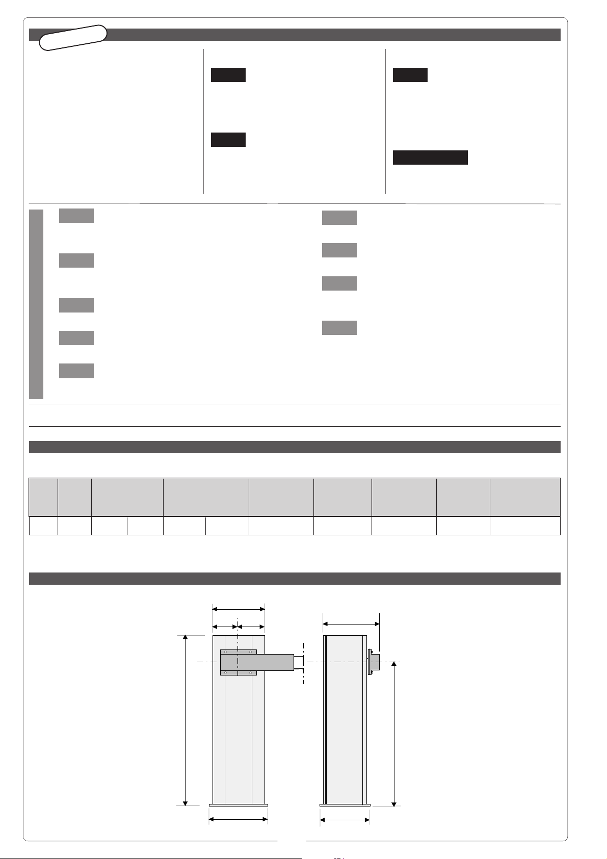
Misure di ingombro - External dimensions - Mesures d'encombrement - Außenabmessungen - Dimensiones máximas
Características Generales
ESPAÑOL
(1)
Servizio intensivo -
Heavy-duty
- Utilisation intensive -
Starkbetrieb
- Servicio intensivo
220
265
270
260
==
1007
884
TIPO
TYPE
TYPE
TYP
TIPO
G4000
G4001
PESO
WEIGHT
POIDS
GEWICHT
PESO
47 Kg
ALIMENTAZIOPNE
POWER SUPPLY
ALIMENTATION
STROMVERSORGUNG
ALIMENTACION
230V a.c. 24V d.c.
ASSORBIMENTO
CURRENT DRAW
ABSORPTION
STROMAUFNAHME
ABSORBENCIA
1,3A max. 15A max
(230V) (24V)
POTENZA MOTORE
MOTOR POWER
PUISSANCE MOTEUR
WIRKLEISTUNG MOTOR
POTENCIA MOTOR
300 W
INTERMIT. LAVORO
DUTY CYCLE
INTERM. TRAVAIL
EINSCHALTDAUER
INTERM. TRABAJO
...
(1)
RAPPORTO RID.
REDUCTION RADIO
RAPPORT REDUCT
REDUKTIONSRAPPORT
RELACIÓN DE REDUC.
1/202
COPPIA
MAX. TORQUE
COUPLE
DREHMOMENT
PAREJA (MOTOR)
200 Nm
TEMPO DI APERTURA
OPENING TIME
TEMPS COURSE
LAUFZEIT
TIEMPO DE RECORRIDO
2 ÷ 6 s
5
A - Armadio in lamiera
di acciaio da 2,5 mm
con finiture di zincatura e
verniciatura (G4000), o in
acciaio inox satinato da 2
mm (G4001), dotato di pre-
disposizioni per l'inserimen-
to di tutti gli accessori di
competenza.
Sportello di ispezione inter-
na fissato all'armadio con
una chiave personalizzata.
B - Base di ancoraggio in
acciaio con finiture di zinca-
tura completa di quattro
zanche e relativi bulloni per
il fissaggio dell'armadio al
pavimento.
C - Flangia attacco sbarra
in acciaio con finiture di zin-
catura; permette un rapido
e sicuro bloccaggio della
sbarra con possibilità di
adattare aste di tipo diver-
so.
D - Sblocco del motoridutto-
re che, grazie ad un cinema-
tismo speciale, è attuato
mediante chiave personaliz-
zata.
E - Motore in corrente conti-
nua a 24 V.
Riduttore irreversibile con
cassa in pressofusione di
alluminio; all'interno opera
un sistema di riduzione a
vite senza fine con lubrifi-
cazione a grasso fluido per-
manente.
- Tutti gli organi di rotazione
sono su cuscinetti a lubrifi-
cazione permanente o snodi
sferici autolubrificanti.
F - N. 1 molla di contrappe-
so e bilanciatura del movi-
mento.
G - Fermi meccanici di sicu-
rezza interni.
H - Gruppo finecorsa.
I - Quadro comando ZL37.
A - Case constructed
in 2.5 mm galvanized
stainless sheet with an
enamel finish (G4000), or in
2 mm. stainless steel, with a
satin finish (G4001), factory-
configured to accept all
required accessories. The
access door for inspection
can be locked onto the case
with a personal key.
B - Mounting base in
galvanized steel, complete
with four anchor stays and
bolts for anchoring the case
to the pavement.
C - The flange is in
galvanized steel. This holder
allows the barrier to be
quickly and securely locked.
D - The gear motor lock
system, thanks to a special
mechanical system, can be
locked with a personal key.
E - Motor: 24V d.c.
Reduction gear: non
reversible, with die-cast
aluminum housing. This unit
uses an internal worm gear
as the reduction system,
and is permanently
lubricated with liquid grease.
- The barrier rotates on
permanently-lubricated
bearings or self-lubricating
ball joints.
F - A spring acts as the
counter- weight/balance sy-
stem (for precise, uniform
movement).
G - An internal shock
absorber/barrier travel stop
is provided.
H - Limit switch unit.
I - Control panel ZL37.
A - Armoire réalisée
en tôle d'acier de 2,5
mm avec finition galvanisée
at vernie (G4000); ou bien
en acier inox satinée de 2
mm. (G4001). concue de
telle facon qu'il est possible
de brancher tous les
accessoires appropriés.
Porte pour le contrôle
doitêtre fixée à l'armoire au
moyen d'une clé
personnalisée.
B – Base d'ancrage en
acier avec finition
galvanisée, comprenant
quatre ètriers et les boulons
correspondants permettant
la fixation de l'armoire au
sol.
C - Bride en acier avec
finition galvanisée. Il permet
un blocage rapide et sûr de
la lisse.
D - Le déblocage du
motoréducteur, grace à un
cinématisme spécial,
s'effectue au moyen d'une
clé personnalisée.
E - Moteur en courant
continu 24V.
Réducteur irréversible avec
boîte en aluminium moulé
sous pression, à l'intérieur
duquel opère un système de
rèduction au moyen d'une
vis sans fin avec lubrification
par graisse fluide perma-
nente. Rotation sur des
roulements à lubrification
permanente ou articulations
sphériques autolubrifiantes.
F - N. 1 ressort de compen-
sation et de balance du
mouvement.
G - Arrêt mecanique de
sécurité.
H - Groupe fins de course.
I - Armoire de commande
ZL37.
A - Armario de chapa
de acero de 2,5 mm
con acabado cincado y
barnizado (G4000), o de
acero inox satinado de 2
mm (G4001), dotado de
predisposiciones para la
introducción de todos los
accesorios.
Portillo para inspeccion
interna fijado por medio de
una Ilave personalizada.
B - Base de anclaje de
acero con acabado cincado
dotada de cuatro grapas y
de los pernos relativos para
la fijación del armario en el
suelo.
C - Brida en acero con
acabado cincado, consiente
el ràpido y seguro bloqueo
de la barra.
D - Desbloqueo del
motorreductor, gracias a un
cinematismo especial,
realizado mediante una
Ilave personalizada.
E - Motor en corriente
continua de 24 V.
Reductor irreversible con
caja en aluminio fundido, en
su interior actúa un sistema
de reducción por tornillo sin
fin con lubricación por grasa
fluida permanente.
- Rotación sobre cojinetes
con lubricación permante y
articulaciones de bola
autolubricantes.
F - N. 1 resorte de
contrapeso y equilibración
del movimiento.
G - Amortiguador tope barra
interno.
H - Grupo final de carrera.
I - Cuadro de mando ZL37.
Descrizione tecnica -
Technical description
- Description technique -
Technische Beschreibung
- Déscripcion técnicabarra
I
GB
A - Schrank:
Werksseitig zum
Einbau des notwendigen
Zubehörs ausgerüstet; aus
verzinktem und lackiertem
Stahlblech, 2,5 mm stark
(G4000) bzw. aus
satiniertem
Volledelstahlblech, 2mm
stark, (G4001). Die
Abdeckplatte wird mittels
individuellem Schlüssel am
Schrank befestigt.
B - Ankerplatte aus
verzinktem Stahl mit vier
Fundamentankern und
dazugeörenden
Ankerschrauben zur
Bodenbefestigung des
Schrankes.
C - DerFlansch aus
verzinktem Stahl
gewährleistet sicheres und
schnelles Schließen der
Schranke, Montage
verschiedener.
D - Entsperren: Das
Entsperren des Getriebe-
motors erfolgt dank eines
Sondergetriebes durch
individuellen Schlüssel.
E - Motor: 24V Gleichstrom.
Untersetzungsgetriebe:
Getriebeumkehrmotor in
Aluminiumdruckgußgehäse,
Schneckenuntersetzungs-
getriebe und Dauerschmier-
ung mittels flüssigem
Schmiermittel. Rotation auf
dauergeschmierten Lagern
oder selbstschmierende
Kugelgelenke.
F - Eine Gegengewicht- und
Gewichtsausgleichsfeder
gewährleistet.
G - Innen eingebauter
Stangen
Feststellstoßdämpfer.
H - Endschaltergruppe.
I - Steuergerät ZL37.
F
D
E
G
H
F
I
B
A
D
C
E
6
200
145
220
265
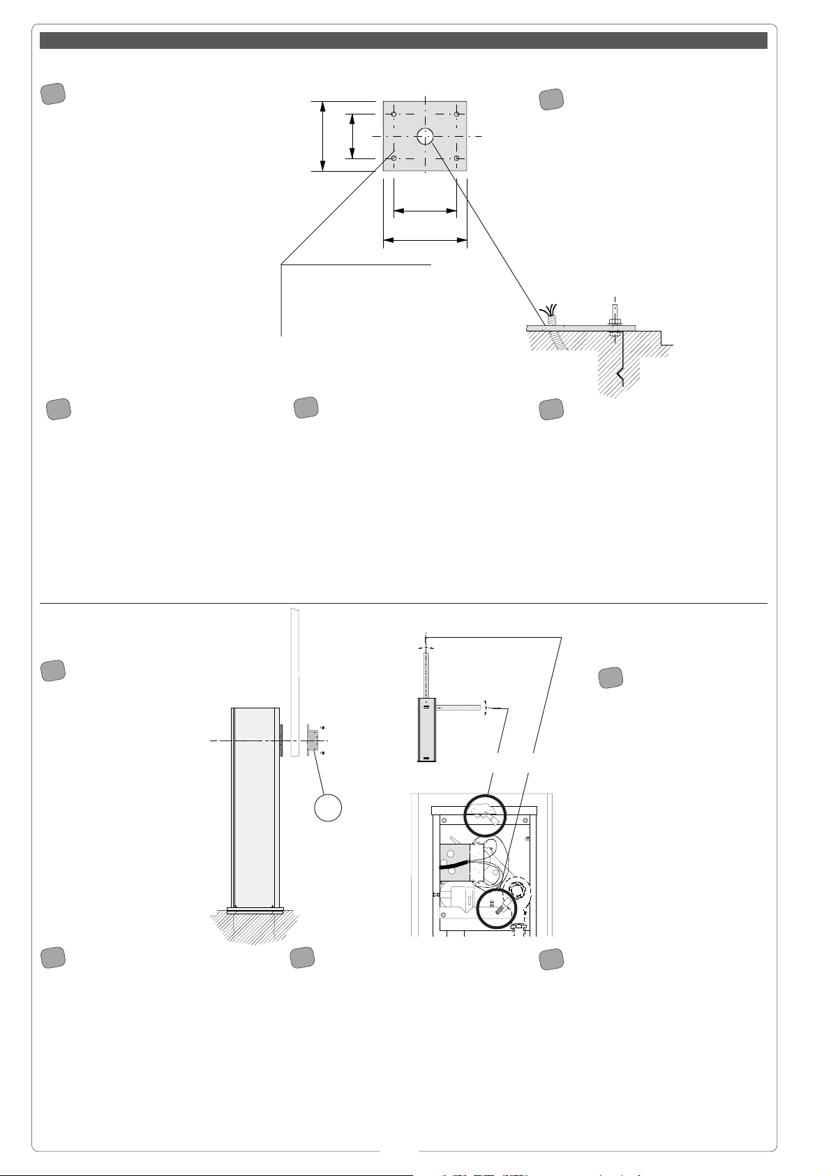
Base di ancoraggio armadio
Mounting base for case
Base d'ancrage armoire
Ankerplatte Schrank
Base de anclaje armario
Montaggio -
Installation
- Montage -
Montage
- Montaje
2) - Procedere alla
posa del gruppo: è consi-
gliabile sistemare l'armadio
con lo sportello ispezio-
nabile vista interna (vedi
pag. 8).
Montare l'asta calcolando
la giusta lunghezza e
fissarla con l'attacco porta-
asta A tramite le quattro
viti in dotazione.
Registrare la linearità
orizzontale e verticale
dell'asta agendo sui
rispettivi fermi meccanici
interni B e C.
2) - Place the unit on
the concrete base: it is good
practice to install the case
so that the access door can
be opened from the interior
of the installation site (see
on page 8).
Mount the barrier as follows:
first, determine the length of
barrier required. Then,
mount the barrier holder
with the four screws
provided.
When is the open position,
the barrier can be
straightened by adjusting
the internal shock absorber/
travel stop (B - C).
2) - Procéder ensuite à la pose
du groupe: il est conseillé de placer
l'armoire avec la porte de contrôle vue
intérieure (voir p. 8).
Monter la lisse en calculant la
longueur exacte, puis fixer le support
de la barre correspondante en
utilisant les quatre vis fournies avec
l'appareillage.
On obtient la linéarité de la lisse en
position d'ouverture en réglant
l'amortisseur de l'arrêt interne B et C
de la lisse.
2) - Gruppe aufstellen: Der
Schrank sollte mit Abdeckplatte zur
Innenseite aufgestellt werden (siehe
Seite 8).
Nach Berechnung der Stangenlänge,
Stange montieren und Stangenhalter
mittels der vier mitgelieferten Schrau-
ben festschrauben.
Die Geradheit der Stange bei
geöffneter Schranke wird mittels
Einstellung des inneren Stangenfest-
stell-Stoßämpfers erzielt (B - C).
2) - Colocar el grupo: se reco-
mienda colocar el armario con el
portillo inspeccionable visto desde el
interior (ver pág. 8).
Montar la barra calculando la longitud
correcta y fijar el porta-barra relativo
mediante los cuatro tornillos del
equipo.
La alineación de la bara abierta se
obtiene ajustando el amortiguador
tope-barra interno (B y C).
I
GB
F
D
E
1) - Predisponer, en función de
las medidas del grupo, una plataforma
de cemento introduciendo las grapas
de anclaje y la base relativa que
consienten fijar el grupo.
La base de fijación debe estar total-
mente horizontal, con los extremos
limpios y la rosca de los tornillos en
superficie.
De la misma deben sobresalir los
cables para las conexiones eléctricas.
1) - Pour a concrete base of the
correct size for installation of the unit.
When pouring, sink the anchoring
stays and the mounting base for the
unit into the concrete.
The concrete base must be perfectly
level and clean from end to end. All
screw threads must be completely
accessible from the surface of the
concrete base.
The electrical cables for the unit must
also protrude from the base.
1) - En tenant compte des
dimensions du groupe, préparer une
plate-forme en ciment dans laquelle
seront noyés les étriers d'ancrage e la
base correspondante qui permettront
de fixer le groupe.
La base de fixation devra être parfaite-
ment de niveau et propre sur toute sa
surface.
Le cables pour le branchement
électrique devront sortir de cette base.
1) - Ein den Abmessungen der
Gruppe entsprechendes Fundament
zum Einbetonieren der an der
Ankerplatte angebrachten
Fundamentanker, die der Befestigung
der Gruppe dienen, vorbereiten.
Die Befestigungsplatte muß eben,
sauber und livelliert sein und die
Ankerschraubengewinde müssen
volkommen frei über der
Fundamentebene liegen.
Die Stromversorgungskabel müssen
aus dem Fundament herausragen.
1) - Predisporre,
dimensionandola in base alle misure
del gruppo, una piazzola di cemento
con annegate le zanche di ancoraggio
e la relativa base che permetteranno il
fissaggio del gruppo.
La base di fissaggio dovrà risultare
perfettamente in bolla, pulita in tutta la
sua estremità con il filetto delle viti
completamente in superficie.
Dalla stessa dovranno emergere i cavi
per il collegamento elettrico.
I
GB
E
D
F
Uscita cavi
Cable exit
Sortie des càbles
Kabelausgang
Salida cables
A
CB
7
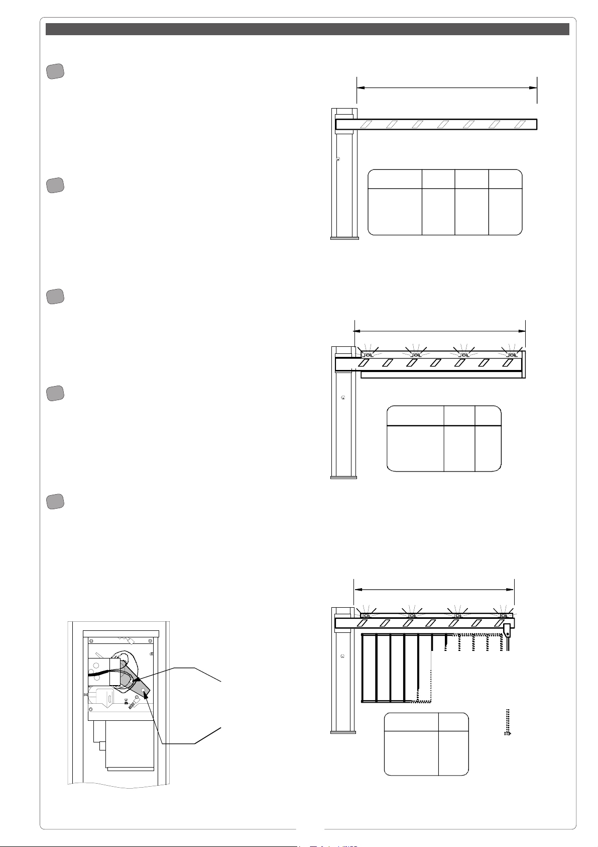
Bilanciamento asta -
Gate rod balancing
- Equilibrage barre -
Stangeausgleich
- Equilibracion barra
La barriera G4000 viene fornita di serie con la
molla montata sulla posizione B.
Se la configurazione finale della vostra barriera lo
richiede (vedi illustrazioni), sbloccare il motoriduttore e
cambiare posizione alla molla.
Per un eventuale bilanciamento fine, vedere la pagina
seguente.
Barrier G4000 is supplied with spring installed at
position B.
If the final configuration of your barrier requires a change
in the position of the spring (see illustrations),
unlock the gear motor and change the position of the
spring.
If precise balancing of the barrier rod is required, see
the next page.
La barrière G4000 est fournie de série avec le
ressort monté sur la position B.
Si cela est nécessaire pour la configuration finale de la
barrière (voir illustrations), débloquer le motoréducteur et
changer la position du ressort.
Pour un éventuel équilibrage fin, voir la page suivante.
Das Schrankenmodell G4000 wird serienmäßig mit
in Position B montierter Feder geliefert.
Wenn es die endgültige Schrankenkonfiguration
erfordern sollte (siehe Abbildungen), den Getriebemotor
entblocken und die Federposition ändern.
Bei eventuell erforderlichem Feinausbalancieren, siehe
nächste Seite.
La barrera G4000 se suministra de serie con el
resorte montado en la posición B.
Si la configuración final de su barrera lo requiere (ver fi-
gura), desbloquear el motorreductor y cambiar la
posición del resorte.
Para un eventual equilibrado fino, ver la página
siguiente.
GB
I
F
D
E
B
A
fissaggio molle
attach springs
fixation ressorts
Federnhalterung
enganche resortes
L
Posizione molla
Spring position
Position ressort
Federeinstellung
Posiciòn resorte
L
m
<2.5 <3.5 <4
AA B
L
con rastrelliera o appoggio mobile
with rack or mobile support
avec tablier ou appui mobile
mit Schrankengitter oder feste Stütze
con estante o apoyo mòvil
Posizione molla
Spri ng position
Position ressort
Federeinstellung
Posiciòn resorte
L
m
<2.5
B
L
Posizione molla
Spring position
Position ressort
Federeinstellung
Posiciòn resorte
L
m
<2.5
A
<3.5
B
8
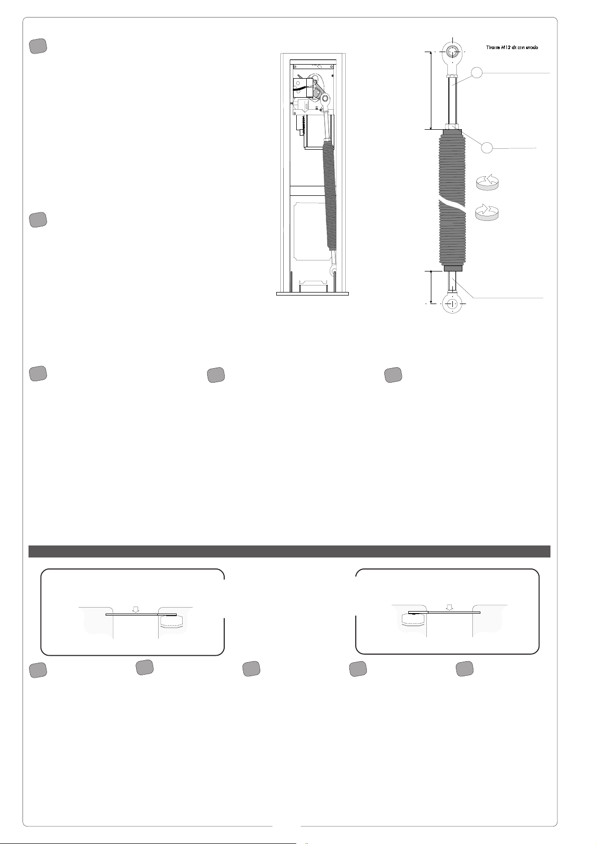
Per bilanciare con precisione
l'asta:
1) - sbloccare il motoriduttore (pag. 5,
part. D);
2) sbloccare il dado di serraggio B del
tirante A;
3) - agire manualmente sulla molla per
aumentare/diminuire la trazione della
stessa fino a che l'asta si stabilizza in
posizione di 45°;
4) - serrare quindi il dado di
bloccaggio e bloccare il motoriduttore.
To balance the barrier rod
precisely, proceed as follows:
1) Unlock the gear motor (p. 5, ref. D);
2) Loosen locknut B on tension rod A;
3) Manually adjust the spring to
increase/decrease its tension until the
barrier rod stabilises at a 45° angle;
4) Now, tighten the locknut and lock
the gear motor.
Para equilibrar con exactitud el
asta:
1) - desbloquear el motorreductor
(pág. 5, det.D);
2) - desbloquear la tuerca de cierre D
del tirante A;
3) - actuar manualmente en el resorte
para aumentar/disminuir la tracción del
mismo hasta que el asta se estabiliza
en la posición de 45º;
4) - enroscar la tuerca de fijación y
bloquear el motorreductor.
Zum präzisen Ausbalancieren
des Schrankenbaums:
1) - den Getriebemotor entblocken
(Seite 5, Detail D);
2) - Die Befestigungsmutter B des
Zugstabs A lockern;
3) - mit der Hand die Federspannung
bis zur endgültigen Stabilisierung des
Schrankenbaums in 45°-Stellung
erhöhen bzw. verringern.
4) - die Befestigungsmutter wieder
festziehen und den Getriebemotor
blockieren.
Pour équilibrer avec précision la
lisse:
1) - débloquer le motoréducteur (p. 5,
dét. D);
2) débloquer l’écrou de serrage B du
tirant A;
3) - Agir manuellement sur le ressort
pour en augmenter/diminuer la traction
jusqu’à ce que la lisse se stabilise en
position
de 45°;
4) - serrer ensuite l’écrou de blocage
et bloquer le motoréducteur.
Barriera dx / sx -
Rod barrier dx / sx
- Barrière dx /sx -
Schranke dx /sx
- Barrera dx /sx
Le barriere
G4000 sono fornite
DX o SX a richiesta.
Se in seguito si vuole
invertire la rotazione,
richiedere la relativa
documentazione.
G4000 barriers
are furnished in right-
hand or left-hand
versions upon
request.
If the direction of
rotation must be
changed at a later
time, contact CAME
for the relative
instructions.
Les barrières
G4000 sont fournies
sur demande côté
droit ou gauche.
Si l’on désire par la
suite invertir la
rotation, demander la
documentation
correspondante.
Die Schranken-
modelle G4000
werden, auf Anfrage,
als Rechts-bzw.
Linksausführung
geliefert. Wenn zu
einem späteren
Zeitpunkt eine
Drehrichtungs-
umkehrung erford-
erlich werden sollte,
dann fordern sie bitte
die entsprechenden
Unterlagen an.
Las barreras
G4000 se suministran
dcha. o izda. a
encargo. En el caso
de que se quisiera po-
steriormente invertir
la rotación, solocitar
la documentación
correspondiente.
GB
I
F
D
E
I
GB
E
D
F
barriera sinistra
Left-hand barrier
Barrière gauche
Liksschranke
Barrera izquierda
LATO INGRESSO
ENTRANCE
SIDE
CÔTÉ ENTRÉE
ZUFAHRTS
-
BZW
.
ZUGANGSSEITE
LADO ENTRADA
ZONA INTERNA -
INSIDE
AREA
- ZONE INTERNE -
INNENBEREICH
ZONA INTERNA
barriera destra
Right-hand barrier
Barrière droite
Rechtsschranke
Barrera derecha
LATO INGRESSO
ENTRANCE
SIDE
CÔTÉ ENTRÉE
ZUFAHRTS
-
BZW
.
ZUGANGSSEITE
LADO ENTRADA
ZONA INTERNA -
INSIDE
AREA
- ZONE INTERNE -
INNENBEREICH
ZONA INTERNA
Tirante ad occhio M12 sx
M12 sx eye tie rod
Tirant à oeillet M12 sx
Ösenhalterung M12 sx
Tirant e a ojal M12 iz do
Dado M12
M12 nut
Écrou M12
Mutter M12
Tuerca M12
Tension rod M12 dx with joint
Tirant M12 dx à articulation
Ösenhalterung M12 dx
Tirante M12 dx ad articulaciòn
80 max.
200 max.
A
B
-
Trazione
Pulling force
Traction
Zugkraft
Tracción
+
 Loading...