

Page 1

Operation Manual
®
NIRFlex
N�500
093020
en
Page 2

Page 3

Table of contents
Table of contents
1 About this manual . . . . . . . . . . . . . . . . . . . . . . . . . . . . . . . . . . . . . . . 7
1.1 Trademarks . . . . . . . . . . . . . . . . . . . . . . . . . . . . . . . . . . . . . . . 7
1.2 Abbreviations . . . . . . . . . . . . . . . . . . . . . . . . . . . . . . . . . . . . . . 7
2 Safety. . . . . . . . . . . . . . . . . . . . . . . . . . . . . . . . . . . . . . . . . . . . . . 8
2.1 User qualification . . . . . . . . . . . . . . . . . . . . . . . . . . . . . . . . . . . . 8
2.2 Proper use . . . . . . . . . . . . . . . . . . . . . . . . . . . . . . . . . . . . . . . 8
2.3 Improper use . . . . . . . . . . . . . . . . . . . . . . . . . . . . . . . . . . . . . . 8
2.4 Safety warnings and safety signs used in this manual . . . . . . . . . . . . . . . . . . 9
2.5 Product safety. . . . . . . . . . . . . . . . . . . . . . . . . . . . . . . . . . . . . 11
2.5.1 General hazards. . . . . . . . . . . . . . . . . . . . . . . . . . . . . . . . . . . . 11
2.5.2 Warning labels on housing and assemblies . . . . . . . . . . . . . . . . . . . . . . 12
2.5.3 Personal protective equipment . . . . . . . . . . . . . . . . . . . . . . . . . . . . 13
2.5.4 Built-in safety elements and measures . . . . . . . . . . . . . . . . . . . . . . . . 13
2.6 General safety rules . . . . . . . . . . . . . . . . . . . . . . . . . . . . . . . . . . 13
3 Technical data . . . . . . . . . . . . . . . . . . . . . . . . . . . . . . . . . . . . . . . . 14
3.1 Materials used. . . . . . . . . . . . . . . . . . . . . . . . . . . . . . . . . . . . . 14
3.2 Technical data basic instrument . . . . . . . . . . . . . . . . . . . . . . . . . . . . 14
3.2.1 Basic instrument . . . . . . . . . . . . . . . . . . . . . . . . . . . . . . . . . . . 14
3.2.2 Computer requirements . . . . . . . . . . . . . . . . . . . . . . . . . . . . . . . . 15
3.3 Non-fiber optic measuring cells . . . . . . . . . . . . . . . . . . . . . . . . . . . . 15
3.3.1 NIRFlex Solids. . . . . . . . . . . . . . . . . . . . . . . . . . . . . . . . . . . . . 15
3.3.2 NIRFlex Solids Transmittance . . . . . . . . . . . . . . . . . . . . . . . . . . . . . 15
3.3.3 NIRFlex Liquids . . . . . . . . . . . . . . . . . . . . . . . . . . . . . . . . . . . . 16
3.4 Fiber-optic measuring cells and accessories. . . . . . . . . . . . . . . . . . . . . . 17
3.4.1 NIRFlex Fiber Optic Solids. . . . . . . . . . . . . . . . . . . . . . . . . . . . . . . 17
3.4.2 NIRFlex Fiber Optic Liquids . . . . . . . . . . . . . . . . . . . . . . . . . . . . . . 17
3.4.3 NIRFlex Fiber Optic SMA . . . . . . . . . . . . . . . . . . . . . . . . . . . . . . . 18
4 Description of function . . . . . . . . . . . . . . . . . . . . . . . . . . . . . . . . . . . 19
4.1 Functional principle . . . . . . . . . . . . . . . . . . . . . . . . . . . . . . . . . . 19
4.2 Measuring cells and their modes . . . . . . . . . . . . . . . . . . . . . . . . . . . 21
4.2.1 Transflectance mode . . . . . . . . . . . . . . . . . . . . . . . . . . . . . . . . . 22
4.2.2 Diffuse reflection mode . . . . . . . . . . . . . . . . . . . . . . . . . . . . . . . . 23
4.2.3 Transmission mode . . . . . . . . . . . . . . . . . . . . . . . . . . . . . . . . . . 24
4.2.4 Diffuse transmission mode . . . . . . . . . . . . . . . . . . . . . . . . . . . . . . 24
4.3 Basic instrument . . . . . . . . . . . . . . . . . . . . . . . . . . . . . . . . . . . 25
4.3.1 Lamp unit . . . . . . . . . . . . . . . . . . . . . . . . . . . . . . . . . . . . . . . 25
4.3.2 Laser unit . . . . . . . . . . . . . . . . . . . . . . . . . . . . . . . . . . . . . . . 26
4.3.3 Standard wheel . . . . . . . . . . . . . . . . . . . . . . . . . . . . . . . . . . . . 26
4.4 NIRWare software suite . . . . . . . . . . . . . . . . . . . . . . . . . . . . . . . . 26
4.4.1 Available NIRWare packages . . . . . . . . . . . . . . . . . . . . . . . . . . . . . 27
4.5 About the software . . . . . . . . . . . . . . . . . . . . . . . . . . . . . . . . . . 28
4.5.1 NIRWare Control System Service . . . . . . . . . . . . . . . . . . . . . . . . . . . 28
4.5.2 NIRWare software suite . . . . . . . . . . . . . . . . . . . . . . . . . . . . . . . . 28
4.5.3 NIRCal chemometric software. . . . . . . . . . . . . . . . . . . . . . . . . . . . . 29
4.6 Measuring cells with their add-ons and accessories . . . . . . . . . . . . . . . . . . 29
4.6.1 Operating panel . . . . . . . . . . . . . . . . . . . . . . . . . . . . . . . . . . . . 29
4.6.2 NIRFlex Solids. . . . . . . . . . . . . . . . . . . . . . . . . . . . . . . . . . . . . 30
3 NIRFlex N-500 Operation Manual, Version E
Page 4

Table of contents
4.6.3 Petri dish add-on for NIRFlex Solids . . . . . . . . . . . . . . . . . . . . . . . . . . 31
4.6.4 Vial add-on for NIRFlex Solids . . . . . . . . . . . . . . . . . . . . . . . . . . . . . 32
4.6.5 Tablet add-on for NIRFlex Solids . . . . . . . . . . . . . . . . . . . . . . . . . . . 32
4.6.6 XL add-on for NIRFlex Solids . . . . . . . . . . . . . . . . . . . . . . . . . . . . . 33
4.6.7 XL add-on with iris aperture for NIRFlex Solids . . . . . . . . . . . . . . . . . . . . 34
4.6.8 XL add-on for B+L sample cups for NIRFlex Solids . . . . . . . . . . . . . . . . . . 34
4.6.9 External Reference for XL and petri dish add-on. . . . . . . . . . . . . . . . . . . . 35
4.6.10 Spinner add-on . . . . . . . . . . . . . . . . . . . . . . . . . . . . . . . . . . . . 35
4.6.11 Flow-cell adapter add-on . . . . . . . . . . . . . . . . . . . . . . . . . . . . . . . 36
4.6.12 NIRFlex Solids Transmittance . . . . . . . . . . . . . . . . . . . . . . . . . . . . . 36
4.6.13 Sample plates for the NIRFlex Solids Transmittance . . . . . . . . . . . . . . . . . . 38
4.6.14 NIRFlex Liquids . . . . . . . . . . . . . . . . . . . . . . . . . . . . . . . . . . . . 39
4.6.15 NIRFlex Fiber Optic Solids . . . . . . . . . . . . . . . . . . . . . . . . . . . . . . . 40
4.6.16 Transflectance adapter for NIRFlex Fiber Optic Solids . . . . . . . . . . . . . . . . . 42
4.6.17 NIRFlex Fiber Optic Liquids . . . . . . . . . . . . . . . . . . . . . . . . . . . . . . 42
4.6.18 NIRFlex Fiber Optic SMA . . . . . . . . . . . . . . . . . . . . . . . . . . . . . . . 44
5 Putting into operation . . . . . . . . . . . . . . . . . . . . . . . . . . . . . . . . . . . . 45
5.1 Transportation lock . . . . . . . . . . . . . . . . . . . . . . . . . . . . . . . . . . 45
5.2 Requirements concerning the installation site . . . . . . . . . . . . . . . . . . . . . 46
5.3 Electrical connection requirements . . . . . . . . . . . . . . . . . . . . . . . . . . 47
5.4 Installing the instrument . . . . . . . . . . . . . . . . . . . . . . . . . . . . . . . . 48
5.4.1 Setting up the Ethernet communication . . . . . . . . . . . . . . . . . . . . . . . . 48
5.4.2 Network integration . . . . . . . . . . . . . . . . . . . . . . . . . . . . . . . . . . 49
5.5 Installing the measuring cells . . . . . . . . . . . . . . . . . . . . . . . . . . . . . 50
5.6 Installing the cover of the NIRFlex Solids Transmittance . . . . . . . . . . . . . . . . 51
5.7 Preparing the transflectance adapter . . . . . . . . . . . . . . . . . . . . . . . . . 52
5.7.1 Adjusting the pathlength of the transflectance adapter to the probe head . . . . . . . 52
5.7.2 Exchanging the spacer ring . . . . . . . . . . . . . . . . . . . . . . . . . . . . . . 54
5.7.3 Installing the transflectance adapter to perform measurements . . . . . . . . . . . . 54
5.8 Installing measurement equipment to the NIRFlex Fiber Optic SMA . . . . . . . . . . 55
5.9 Starting up the system . . . . . . . . . . . . . . . . . . . . . . . . . . . . . . . . 56
5.9.1 System Suitability Test. . . . . . . . . . . . . . . . . . . . . . . . . . . . . . . . . 56
5.9.2 Temperature tests in detail. . . . . . . . . . . . . . . . . . . . . . . . . . . . . . . 56
5.9.3 NIR linearity test . . . . . . . . . . . . . . . . . . . . . . . . . . . . . . . . . . . 56
5.9.4 Signal-to-noise ratio determination . . . . . . . . . . . . . . . . . . . . . . . . . . 57
5.9.5 Wavenumber stability test . . . . . . . . . . . . . . . . . . . . . . . . . . . . . . . 57
5.9.6 SST with NIRFlex Solids Transmittance . . . . . . . . . . . . . . . . . . . . . . . . 57
5.10 Reference measurements . . . . . . . . . . . . . . . . . . . . . . . . . . . . . . . 57
6 Operation . . . . . . . . . . . . . . . . . . . . . . . . . . . . . . . . . . . . . . . . . . 59
6.1 General recommendations for measuring solids . . . . . . . . . . . . . . . . . . . . 59
6.2 General recommendations for measuring liquids . . . . . . . . . . . . . . . . . . . 60
6.3 Starting a measurement . . . . . . . . . . . . . . . . . . . . . . . . . . . . . . . . 60
6.4 NIRFlex Solids. . . . . . . . . . . . . . . . . . . . . . . . . . . . . . . . . . . . . 61
6.4.1 Reference measurement for the Petri dish add-on. . . . . . . . . . . . . . . . . . . 61
6.4.2 Reference measurement for the XL add-on . . . . . . . . . . . . . . . . . . . . . . 61
6.5 NIRFlex Solids Transmittance . . . . . . . . . . . . . . . . . . . . . . . . . . . . . 61
6.6 NIRFlex Liquids . . . . . . . . . . . . . . . . . . . . . . . . . . . . . . . . . . . . 62
6.7 NIRFlex Fiber Optics . . . . . . . . . . . . . . . . . . . . . . . . . . . . . . . . . 64
6.7.1 NIRFlex Fiber Optic Solids. . . . . . . . . . . . . . . . . . . . . . . . . . . . . . . 64
6.7.2 NIRFlex Fiber Optic Liquids . . . . . . . . . . . . . . . . . . . . . . . . . . . . . . 65
6.7.3 NIRFlex Fiber Optic SMA . . . . . . . . . . . . . . . . . . . . . . . . . . . . . . . 65
4
NIRFlex N-500 Operation Manual, Version E
Page 5

Table of contents
7 Maintenance . . . . . . . . . . . . . . . . . . . . . . . . . . . . . . . . . . . . . . . . . 66
7.1 Cleaning. . . . . . . . . . . . . . . . . . . . . . . . . . . . . . . . . . . . . . . . 66
7.2 Housing . . . . . . . . . . . . . . . . . . . . . . . . . . . . . . . . . . . . . . . . 66
7.2.1 Optical surfaces and probes. . . . . . . . . . . . . . . . . . . . . . . . . . . . . . 67
7.2.2 Cleaning of the External Reference . . . . . . . . . . . . . . . . . . . . . . . . . . 67
7.2.3 Cleaning of the Transflectance adapter . . . . . . . . . . . . . . . . . . . . . . . . 68
7.3 Advanced testing with NIRWare Automatic Diagnose . . . . . . . . . . . . . . . . . 69
7.4 Lamp module replacement . . . . . . . . . . . . . . . . . . . . . . . . . . . . . . 70
7.5 Laser unit replacement . . . . . . . . . . . . . . . . . . . . . . . . . . . . . . . . 74
7.6 Filter pad replacement. . . . . . . . . . . . . . . . . . . . . . . . . . . . . . . . . 77
7.7 Main fuse replacement . . . . . . . . . . . . . . . . . . . . . . . . . . . . . . . . 78
7.7.1 Measuring cell fuse replacement . . . . . . . . . . . . . . . . . . . . . . . . . . . 78
7.8 NIRFlex Solids. . . . . . . . . . . . . . . . . . . . . . . . . . . . . . . . . . . . . 79
7.9 NIRFlex Liquids . . . . . . . . . . . . . . . . . . . . . . . . . . . . . . . . . . . . 79
7.10 Customer service . . . . . . . . . . . . . . . . . . . . . . . . . . . . . . . . . . . 80
8 Storage, transport and disposal . . . . . . . . . . . . . . . . . . . . . . . . . . . . . . 81
8.1 Storage and transport . . . . . . . . . . . . . . . . . . . . . . . . . . . . . . . . . 81
8.2 Disposal. . . . . . . . . . . . . . . . . . . . . . . . . . . . . . . . . . . . . . . . 81
9 Spare parts and accessories . . . . . . . . . . . . . . . . . . . . . . . . . . . . . . . . 83
9.1 Scope of delivery . . . . . . . . . . . . . . . . . . . . . . . . . . . . . . . . . . . 83
9.1.1 Interferometer . . . . . . . . . . . . . . . . . . . . . . . . . . . . . . . . . . . . . 83
9.1.2 Measuring cells . . . . . . . . . . . . . . . . . . . . . . . . . . . . . . . . . . . . 84
9.1.3 Software . . . . . . . . . . . . . . . . . . . . . . . . . . . . . . . . . . . . . . . 85
9.1.4 Standard accessories . . . . . . . . . . . . . . . . . . . . . . . . . . . . . . . . . 86
9.1.5 Optional accessories . . . . . . . . . . . . . . . . . . . . . . . . . . . . . . . . . 87
9.2 NIRFlex spectrometer . . . . . . . . . . . . . . . . . . . . . . . . . . . . . . . . . 90
9.3 NIRFlex Solids. . . . . . . . . . . . . . . . . . . . . . . . . . . . . . . . . . . . . 91
9.4 NIRFlex Solids Transmittance . . . . . . . . . . . . . . . . . . . . . . . . . . . . . 92
9.5 NIRFlex Liquids . . . . . . . . . . . . . . . . . . . . . . . . . . . . . . . . . . . . 92
9.6 NIRFlex Fiber Optic Liquids . . . . . . . . . . . . . . . . . . . . . . . . . . . . . . 92
9.7 NIRFlex Fiber Optic Solids. . . . . . . . . . . . . . . . . . . . . . . . . . . . . . . 92
9.8 NIRFlex Fiber Optic SMA . . . . . . . . . . . . . . . . . . . . . . . . . . . . . . . 93
9.9 Transflectance adapter . . . . . . . . . . . . . . . . . . . . . . . . . . . . . . . . 93
10 Declarations and requirements. . . . . . . . . . . . . . . . . . . . . . . . . . . . . . . 94
10.1 FCC requirements (for USA and Canada) . . . . . . . . . . . . . . . . . . . . . . . 94
10.2 Declaration of conformity . . . . . . . . . . . . . . . . . . . . . . . . . . . . . . . 95
5 NIRFlex N-500 Operation Manual, Version E
Page 6

1 About this manual
This manual describes the NIRFlex N-500 including its standard software and provides all information
required for its safe operation and to maintain it in good working order.
It is addressed to laboratory personnel and operators in particular.
Read this manual carefully before installing and running your system and note the safety precautions
in section 2 in particular. Store the manual in the immediate vicinity of the instrument, so that it can be
consulted at any time.
No technical modifications may be made to the instrument without the prior written agreement of
Buchi. Unauthorized modifications may affect the system safety or result in accidents. Technical data
are subject to change without notice.
NOTE
The symbols pertaining to safety are explained in section 2.
1 About this manual
This manual is copyright. Information from it may not be reproduced, distributed or used for competitive purposes, nor made available to third parties. The manufacture of any component with the aid of
this manual without prior written agreement is also prohibited.
The English manual is the original language version and serves as basis for all translations into
other languages. If you need another language version of this manual, you can download available
versions at www.buchi.com.
1.1 Trademarks
The following product names and any registered and unregistered trademarks mentioned in this
manual are used for identification purposes only and remain the exclusive property of their respective
owners:
NIRFlex•
NIRCal•
®
Kimwipes•
Meliseptol•
1.2 Abbreviations
®
is a registered trademark of BÜCHI Labortechnik AG
is a registered trademark of BÜCHI Labortechnik AG
®
is a registered trademark of Kimberly Clark
®
is a registered trademark of B. Braun
EMEA: European Agency for the Evaluation of Medicinal Products
EP: European Pharmacopoeia
FDA: Food & Drug Administration
MTBF: Mean time between failures
NIR: Near infrared
PMMA: Polymethylmetacrylat
S/N: Signal to noise ratio
USP: United States Pharmacopeia
6 NIRFlex N-500 Operation Manual, Version F
Page 7

2 Safety
This section introduces the safety concept of the instrument and contains general rules of behavior
and warnings from direct and indirect hazards concerning the use of the product.
For the users safety, all safety instructions and safety messages in the individual sections shall
be strictly observed and followed. Therefore, the manual must always be available to all persons
performing any tasks described herein.
2.1 User qualification
The instrument may only be used by laboratory personnel and other persons who on account of
training and professional experience know the potential dangers that can develop when operating the
instrument.
Untrained personnel, or persons who are currently being trained, require careful supervision by a
qualified person. This Operation Manual serves as a basis for training.
2 Safety
2.2 Proper use
The NIRFlex N-500 has been designed and built as a rugged analysis instrument. It serves to determine the matter and concentration of substances in samples above its measuring tolerance limit (no
trace analysis). Thanks to its ruggedness, the instrument is suitable for use on most production floors
(at-line, near-line). For suitable environmental conditions see tables of technical data.
The NIRFlex N-500 system can be applied for the following tasks:
Qualitative analysis
Differentiation of chemically different substances (e.g. raw material testing of incoming goods);•
Differentiation of chemically similar substances or substance grades.•
Quantitative analysis
Determination of quantifiable product properties such as concentrations or physical parameters •
(viscosity, particle size).
2.3 Improper use
Any other use than the one stated above and any application that does not comply with the technical
data is considered to be improper use. Improper use can cause hazardous situations for the operator
and / or for the instrument and might cause consequential property damage.
The operator bears the sole risk for any damages or hazards caused by improper use!
In particular, the following uses shall not be permitted
Installation and use in environments where explosion protection is required•
User repair and maintenance work other than described in this manual•
Reuse of sample material for production that has been in direct contact with non-food safe mate-•
rials and surfaces
7 NIRFlex N-500 Operation Manual, Version F
Page 8
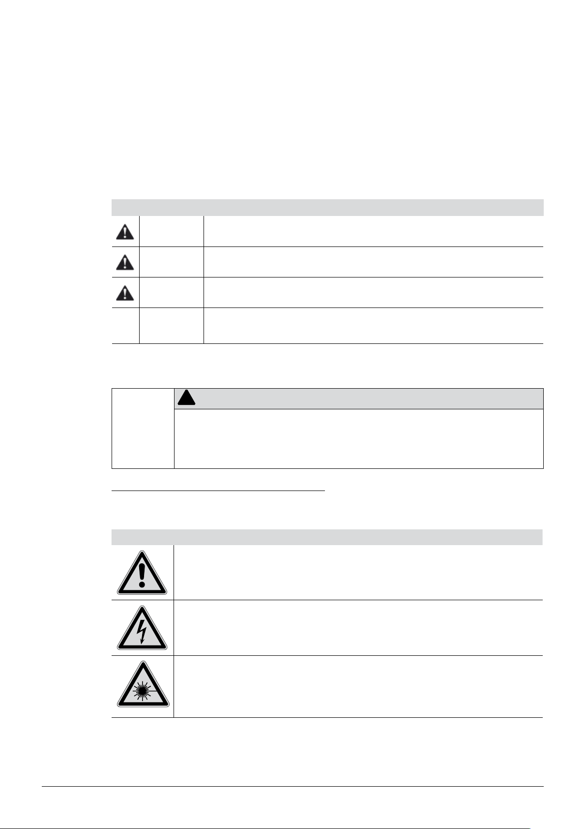
2.4 Safety warnings and safety signs used in this manual
!
DANGER, WARNING, CAUTION and NOTICE are standardized signal words for identifying levels of
hazards and risks related to personal injury and property damage. All signal words, which are related
to personal injury are accompanied by the general safety sign.
For your safety it is important to read and fully understand the table below with the different signal
words and their definitions!
Sign Signal word Definition Risk level
DANGER
Indicates a hazardous situation which, if not avoided, will result in
death or serious injury.
2 Safety
★★★★
WARNING
CAUTION
NOTICE
no
Supplementary safety information symbols may be placed in a rectangular panel on the left to the
signal word and the supplementary text (see example below).
Space for
supplementary
safety
information
symbols.
Table of supplementary safety information symbols
The reference list below incorporates all safety information symbols used in this manual and their
meaning.
Symbol Meaning
Indicates a hazardous situation which, if not avoided, could result
in death or serious injury.
Indicates a hazardous situation which, if not avoided, may result
in minor or moderate injury.
Indicates possible property damage, but no
practices related to personal injury.
SIGNAL WORD
Supplementary text, describing the kind and level of hazard / risk seriousness.
List of measures to avoid the herein described, hazard or hazardous situation.•
...•
...•
★★★☆
★★☆☆
★☆☆☆
(property damage only)
General warning
Electrical hazard
LASER emission
8 NIRFlex N-500 Operation Manual, Version F
Page 9

Symbol Meaning
Explosive gases, explosive environment
Hot item, hot surface
Device damage
Fragile components
2 Safety
Unplug device
Wear protective goggles
Wear protective gloves
Do not dispose as unsorted household waste!
Additional user information
Paragraphs starting with NOTE transport helpful information for working with the device / software or
its supplementaries. NOTEs are not related to any kind of hazard or damage (see following example).
NOTE
Useful tips for the easy operation of the instrument / software.
9 NIRFlex N-500 Operation Manual, Version F
Page 10
2.5 Product safety
!
!
!
The NIRFlex N-500 has been designed and built in accordance with state-of-the-art technology, at the
time of development. Safety warnings in this manual (as described in section 2.4) serve to make the
user alert to and avoid hazardous situations emanating from residual dangers by giving appropriate
counter measures.
However, risks to users, property and the environment can arise when the instrument is damaged,
used carelessly or improperly.
Always follow laboratory safety rules. E.g. wear personal protective equipment such as protective eye
googles, protective clothing and gloves when working with the instrument.
2.5.1 General hazards
The following safety messages show hazards of general kind which may occur when handling the
instrument. The user shall observe all listed counter measures in order to achieve and maintain the
lowest possible level of hazard.
NOTE
The instrument contains a laser for wavenumber calibration. When closed the instrument is considered a Class 1 laser product (DIN Standard: GZS values DIN VDE 0837). When the housing is open,
the instrument is considered a Class 3R laser product.
2 Safety
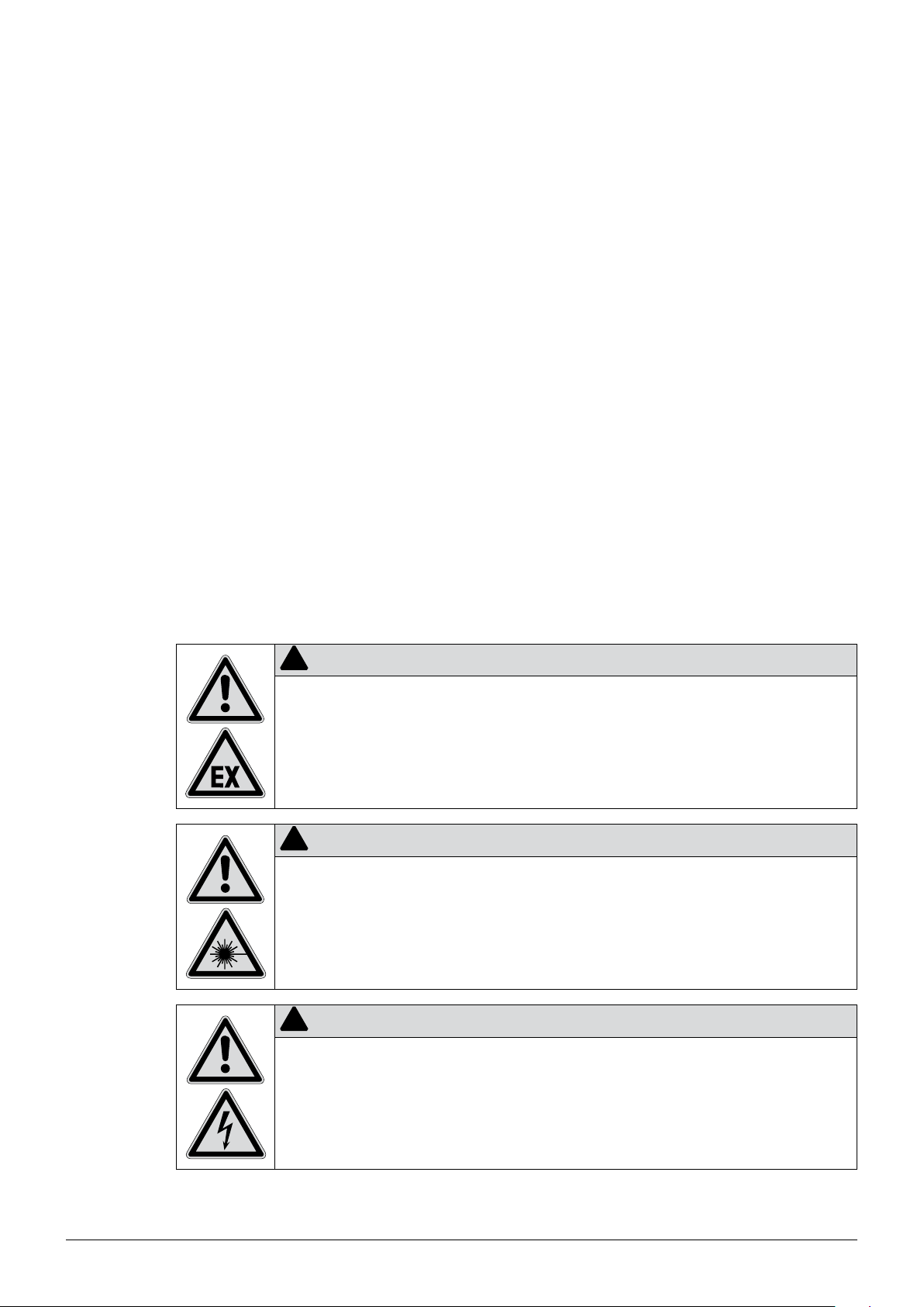
Additional warning messages can be found whenever actions and situations described in this manual
are related to situational hazards.
DANGER
Death or serious injuries by use in explosive environments.
Do not store or operate the instrument in explosive environments•
Remove all sources of flammable vapors•
Do not store chemicals in the vicinity of the device•
Only operate and maintain the device in environment with sufficient ventilation•
WARNING
Serious eye damage by unfiltered LASER emission at open housing.
Do not operate the instrument with open or damaged housing•
Caution
Minor or moderate injuries by dangerous current.
Do not spill any liquids over the Measurement Cell connector of the instrument•
10 NIRFlex N-500 Operation Manual, Version F
Page 11

2 Safety
Risk of instrument damage by mechanical shocks.
2.5.2 Warning labels on housing and assemblies
The following warning sticker(s) can be found on the housing or assemblies of the NIRFlex N-500:
Symbol Meaning Location
Hot item, hot surface Inside housing, next to lamp modules
LASER emission
NOTICE
Do not move the instrument when it is active•
Do not drop the instrument or its components•
Keep external vibrations away from the instrument•
Do not transport the instrument without transportation lock engaged•
Sticker at the rear side
Sticker inside housing, at the LASER module
Electrical hazard HV supply LASER
Device labels Meaning Location
FCC declaration Sticker at the rear side
See text. Sticker at the rear side
LASER emission class Sticker at the rear side
See text.
11 NIRFlex N-500 Operation Manual, Version F
Sticker on top of the housing, near the Measurement Cell connector.
Page 12

Device labels Meaning Location
2.5.3 Personal protective equipment
Safety precautions and personal protective equipment might be necessary to comply with industrial
safety standards in some working environments. However, for standard operation with the instrument,
no additional protective equipment is necessary.
2.5.4 Built-in safety elements and measures
The instrument is equipped with the following safety elements:
One outer filter elements with covering frame•
Multiple magnet sensors to detect opening of any housing element•
Multiple overtemperature sensors to monitor thermal spots inside the instrument•
Transportation lock of interferrometer•
2 Safety
LASER emission Sticker inside housing, at the LASER module
2.6 General safety rules
Responsibility of the operator
The head of the laboratory is responsible for training his/her personnel.
The operator shall inform the manufacturer without delay of any safety-related incidents which might
occur during operation of the instrument or its accessories. Legal regulations, such as local, state and
federal laws applying to the instrument or its accessories must be strictly followed.
Duty of maintenance and care
The operator is responsible for the proper condition of instrument. This includes maintenance, service
and repair jobs that are performed on schedule as described in this manual. Any work, not explicitly
described in this manual must be performed by authorized and trained personnel (e.g. service technicians) only.
Spare parts to be used
Use only genuine consumables and spare parts for maintenance to assure good system performance,
reliability and safety. Any modifications of spare parts or assemblies are only allowed with the prior
written permission of the manufacturer.
Modifications
Modifications to the instrument are only permitted after prior consultation and with the written approval
of the manufacturer. Modifications and upgrades shall only be carried out by an authorized Buchi technical engineer. The manufacturer will decline any claim resulting from unauthorized modifications.
12 NIRFlex N-500 Operation Manual, Version F
Page 13

3 Technical data
This section introduces the reader to the instrument specifications and the list of materials used.
3.1 Materials used
Materials used
Component Material designation
Base plate Aluminium / stainless steel
Wedges TeO
Polarizers Glass
Housing Polyurethane foam
Detector InGaAs
Magnets NdFeB
3 Technical data
2
3.2 Technical data basic instrument
3.2.1 Basic instrument
Technical data basic instrument
Dimensions housing ( W x H x D) 350 x 250 x 450 mm
Electric power supply 100−230 VAC ± 10 %, 50/60 Hz, 350 W
Ambient conditions < 80 % relative humidity for T < 31 °C, linear decreasing
Ambient temperature 5−35 °C ( 25 ± 5 °C recommended)
Pollution degree 2
Installation category II
Spectral range 800 - 2500 nm (default 1000 - 2500 nm)
Resolution 8 cm-1 (with boxcar apodisation)
Type of interferometer Polarisation interferometer with TeO
Wavenumber accuracy ± 0.2 cm
S/N 10000 (peak-to-peak noise of a linear corrected baseline
Number of scans/sec. 2−4
Analog digital converter 24 bit
Type of lamp/lifetime lamp (MTBF) Tungsten halogen lamp / 12000 h (2 x 6000 h)
Type of laser 12 VDC HeNe, wavelength at 632.992 nm
Ethernet connection 100 Mbit/s
to 67 % at 35 °C, max. 2500 m, for indoor use only
-1
12‘500 - 4‘000 cm
(default 10‘000 - 4‘000 cm-1)
(if not specified otherwise for measuring cell)
wedges
-1
(measured with HF gascell at an ambient
2
temperature of 25 °C ± 5 °C)
-1
between 5600−6000 cm
, measured with NIRFlex
Liquids, 2 x 64 scans, Blackman apodisation)
13 NIRFlex N-500 Operation Manual, Version F
Page 14

3.2.2 Computer requirements
The spectral data are collected in the NIRWare database on the PC. The following minimum configuration is needed for the PC running the NIRWare Software Suite (1.4):
Computer hardware and software requirements
Windows XP Professional (32-bit only), SP3 or higher
/ Windows 7 Professional / Ultimate (32-bit only)
Please consider a more powerful computer system if you are working with a bigger amount of data,
doing automated (cyclic) measurements or calculating your own calibrations.
3 Technical data
Dual Core 2.4 GHz or faster
3 GB RAM or more (2 GB minimum)
10 GB of free harddisk space
CD– ROM drive
2 Network adapter (1 adapter minimum)
Display res.: 1280 x 1024 (1024 x 768 minimum)
3.3 Non-fiber optic measuring cells
3.3.1 NIRFlex Solids
Technical data NIRFlex Solids
Detector extended range InGaAs (temperature controlled)
Electric power supply 100 - 230 VAC ± 10%, 50/60 Hz, 20 W
Ambient conditions < 80 % relative humidity for T < 31 °C, linear decreasing to 67 % at
Ambient temperature 5−35 °C ( 25 ± 5 °C recommended)
Pollution degree 2
Installation category II
3.3.2 NIRFlex Solids Transmittance
Technical data NIRFlex Solids Transmittance
Detector InGaAs (temperature controlled)
Electric power supply 100 - 230 VAC ± 10%, 50/60 Hz, 20 W
Ambient conditions < 80 % relative humidity for T < 31 °C, linear decreasing
Ambient temperature 5−35 °C ( 25 ± 5 °C recommended)
Pollution degree 2
Installation category II
Spectral range 12’500 - 6’000 cm
35 °C, max. 2500 m, for indoor use only
to 67 % at 35 °C, max. 2500 m, for indoor use only
-1
(recommended range 11’520 - 6000 cm-1)
800−1660 nm (recommended range 870 - 1660 nm)
Photometric dynamic range 0 - 6 AU
14 NIRFlex N-500 Operation Manual, Version F
Page 15

3 Technical data
Technical data NIRFlex Solids Transmittance (cont.)
Photometric linearity The “addition of filter technique” has been used.
A 2% transmission filter and a wavelength standard
(Rare Earth Oxide mixture) were used for the addition.
Both filters were measured individually and together in
series. The addition of the individual measurements has
been compared with the measurement of both filters ihn
-7
T
Typical signal-to-noise ratio
series. The difference had been < 2 x 10
at 7’876 cm
-1
rms for spectral segments of 300 cm-1 in the range of
11’000 - 6’500 cm
-1
open beam
5 mm white standard
3.3.3 NIRFlex Liquids
Technical data NIRFlex Liquids
Detector extended range InGaAs (temperature controlled)
Electric power supply provided from NIRFlex N-500 100−230 VAC ± 10 %, 50/60 Hz, 250 W
Ambient conditions < 80 % relative humidity for T < 31 °C, linear
Ambient temperature 5−35 °C ( 25 ± 5 °C recommended)
Pollution degree 2
Installation category II
Sample temperature range Ambient temperature plus 10 °C up to 65 °C
Reproducibility of set sample temperature
Temperature overshoot < 5 °C
Overheating protection, automatic switch-off T > 90 °C
Diameter of measurement spot 2 mm
Type of cuvettes to be used Standard cuvettes 12.5 x 12.5 x 45 mm with path-
Time needed to reach a stable control of the set temperature Ambient temperature to 65 °C: 15 min
mean 2 x 10⁻⁵ AU (16 scans; Blackman apodization)
-5
mean 10 x 10
AU (64 scans; Blackman apodization)
decreasing to 67 % at 35 °C, max. 2500 m, for indoor
use only
± 0.5 °C
length of 2 mm, when spacers are used, 1, 5, 10 mm
cuvettes can be inserted as well
15 NIRFlex N-500 Operation Manual, Version F
Page 16

3.4 Fiber-optic measuring cells and accessories
3.4.1 NIRFlex Fiber Optic Solids
Technical data NIRFlex Fiber Optic Solids
Detector extended range InGaAs (temperature controlled)
Electric power supply 100−230 VAC ± 10 %, 50/60 Hz, 20 W
Ambient conditions < 80 % relative humidity for T < 31 °C, linear decreasing
to 67 % at 35 °C, max. 2500 m, for indoor use only
Ambient temperature 5−35 °C ( 25 ± 5 °C recommended)
Pollution degree 2
Installation category II
Temperature range at probe tip 0 °C−80 °C
Standard length of fiber optic probe 2 m (available up to 5 m)
Accessories
3 Technical data
Technical data Transflectance adapter (Fiber Optic Solids)
Max. operating temperature 120 °C
Material Transflectance sleeve material: Steel no. 1.4435
Available pathlengths 0.5 mm, 1 mm, 1.5 mm
3.4.2 NIRFlex Fiber Optic Liquids
Technical data NIRFlex Fiber Optic Liquids
Detector extended range InGaAs (temperature controlled)
Electric power supply 100−230 VAC ± 10 %, 50/60 Hz, 20 W
Ambient conditions < 80 % relative humidity for T < 31 °C, linear decreasing
Ambient temperature 5−35 °C ( 25 ± 5 °C recommended)
Pollution degree 2
Installation category II
Temperature range of the probe head at the probe tip 0 °C−150 °C
Max. pressure at the probe tip 6 bar
Standard length of fiber optic probe 2 m (available up to 7 m)
Pathlength 2 mm
Spacer ring material: Steel no. 1.4305
Transflectance adapter window: Quartz glass
(Infrasil 303) sealed with fluorine rubber O-rings
to 67 % at 35 °C, max. 2500 m, for indoor use only
16 NIRFlex N-500 Operation Manual, Version F
Page 17

3.4.3 NIRFlex Fiber Optic SMA
Technical data NIRFlex Fiber Optic SMA
Detector extended range InGaAs (temperature controlled)
Electric power supply 100−230 VAC ± 10 %, 50/60 Hz, 20 W
Ambient conditions < 80 % relative humidity for T < 31 °C, linear decreasing
Ambient temperature 5−35 °C ( 25 ± 5 °C recommended)
Pollution degree 2
Installation category II
NOTE
Limit ranges of environmental conditions at the point of measurement highly depend on individual
accessories (i.e. process probe, flow cell, etc.).
3 Technical data
to 67 % at 35 °C, max. 2500 m, for indoor use only
17 NIRFlex N-500 Operation Manual, Version F
Page 18

4 Description of function
This section explains the basic principle of the instrument, shows how it is structured and gives a
functional description of the assemblies.
4.1 Functional principle
The NIRFlex N-500 is a modular optical instrument (basic instrument and measuring cell) to determine
the matter and concentration of substances in samples.
In detail, the NIRFlex N-500 is a Fourier Transformation Near Infrared spectrometer (FT-NIR). It generates an invisible near infrared interferogram beam which interacts with the molecules of a sample,
generating a characteristic feedback. The feedback is picked up via a measurement cell by a detector
and mathematically processed via Fourier transformation into a spectrum. This spectrum is used to
extract the requested material information.
Inside the spectrometer, a laser beam is used as a high-precision wavelength reference to allow best
possible reproducibility and accuracy of detection.
4 Description of function
Advantages of FT-NIR polarization inteferometer
Simultaneous measurement of all wavenumbers giving an improved signal-to-noise ratio•
Higher intensity giving an improved signal-to-noise ratio and short measuring times•
Laser as wavenumber reference giving high wavenumber stability and good data •
transferability
Single-beam interferometer without typical double-beam divergence for mechanically and tempera-•
ture stable beam alignment
More robust design than standard Michelson interferometer•
How the interferogram is generated
An interferogram is an interference pattern of phase-shifted beams. The NIRFlex N-500 is a single-
beam polarisation interferometer, generating its interferogram in four steps:
Step 1— Polarization of the light source output
The polarizer B generates a well-defined polarization output of the undefined polarized light, emitted
by the light source A. Thus, only diagonally polarized light is transmitted.
Step 2 — Beam splitting and orthogonal polarization
The polarized light enters a double refracting block (comparator) C. Here, the light is broken down
into two, orthogonally polarized components with a small, static phase shift.
Step 3 — Generating the ongoing phase shift
An assembly of two double refracting wedges is arranged after the comparator. Wedge D is
stationary, while wedge E is constantly shifted back and forwards by a fast linear-drive. The movement and the geometric arrangement provides a change of thickness in the light path. This leads to an
ongoing phase shift between the light beams.
Step 4 — Beam recombination and interferogram output
A second polarizer F converts the phase shifted beams into a single light output with intensity variation – the interferogram.
18 NIRFlex N-500 Operation Manual, Version F
Page 19

4 Description of function
Reference laser control
The laser deliveres a constant, wavelength-stable beam of 633 nm. The laser beam a is coupled into
the NIR beam b to pass the interferometer before being decoupled d and analysed by the “Laser
feedback sensor” e. A fraction of the beam is splitted at the polarizer b and picked up by an intensity sensor c to monitor the laser beam quality. The position and movement-frequency of the wedge
by the linear drive f causes an alternating relative phase shift of the laser light. Being reflected by the
second polarizer d, the phase shift generates an alternating amplitude. This alternating amplitude is
detected via the the “Laser sensor” e, giving precise information about velocity and (relative) position
of the wedge. The feedback signal is used to control the velocity of the linear drive f as well as to set
the sampling-points of the NIR interferogram.
H G
Effective NIR light path
A
B
NIR light source assembly with spare lamp and motorized parabolic reflector
First polarizer
a
F + b
c
LASER – 633 nm
DE
B
f
Spare lamp
e
+ dC
A
C
D
E
F
G
H
Reference laser signal path
a
b
c
d
e
f
19 NIRFlex N-500 Operation Manual, Version F
Comparator (double refracting block)
Stationary double refracting wedge
Moving double refracting wedge
Second polarizer
Sample
Interferogram detector
Laser output window
Second polarizator (works as a beam splitter for the laser)
Laser output-power sensor
First polarizer
Laser feedback detector
Linear motor for wedge movement
Page 20

Data processing and interferogram analysis
The NIR light interacts with the sample G material in different ways, leaving a characteristical finger-
print on the interferogram. At liquids the light is mostly transmitted and at solids reflected. The
remaining light is collected by the detector H. The built-in computer further processes the raw signal.
Process steps Result
Signal preprocessing Interferogram
Fourier transformation Raw spectrum
Signal background correction Spectrum of sample
Chemometric analysis of the spectral data Sample analysis
Display of the result via NIRWare Operator on the attached monitor Sample analysis is displayed
4.2 Measuring cells and their modes
The NIRFlex N-500 system is of modular design. The interferometer is located in the basic instrument.
Different measuring cell modules for different kinds of sample materials can be easily attached to the
basic intrument. To choose the best measuring cell for a specific range of samples the optical properties of the sample material must be know.
4 Description of function
Measuring cell matrix
Sample characteristics
(for NIR light)
Diffuse reflection 4.2.1 NIRFlex Solids;
Transmission 4.2.3 NIRFlex Liquids;
Section Measuring cell Typical application
Predominantly non-translucent
NIRFlex Fiber Optic Solids;
NIRFlex Fiber Optic SMA*
materials such as most tablets,
cereals and powders
Translucent and transparent liquids
NIRFlex Fiber Optic Liquids
NIRFlex Fiber Optic SMA*
Diffuse transmission 4.2.4 NIRFlex Solids Transmittance Predominantly translucent solids
such as some tables, crystal
powders and other light conducting
materials
Transflectance 4.2.5 NIRFlex Fiber Optic Solids / NIRFlex
Solids with Transflectance Adapter;
NIRFlex Fiber Optic SMA*
*Depending on the custom accessory
and measurement setup
Solids with weak diffuse reflection
and low transmission rate charac-
teristics
20 NIRFlex N-500 Operation Manual, Version F
Page 21

4.2.1 Transflectance mode
Translucent and opaque liquids can be analyzed via transflectance mode. The light penetrates the
liquid, is diffusely reflected by the reference plate and passes the sample a second time. The transflected rays contain the spectral information of the sample.
Factors that can influence the measurement:
Not enough sample material available•
Air bubbles in the measurement path and under the transflectance cover•
Sample not homogeneous or representative•
Temperature of sample material•
Sample cup or transflectance cover inadequate (e.g. cup material and thickness, blind spots, dirt •
etc.)
NIRFlex Solids:
Diffuse reflecting / reference plate
4 Description of function
Sample cup / petri dish
NIR light
NIRFlex Fiber Optic Solids / SMA:
Small, defined gap for liquid samples
Detector
Fiber optics (example)
Small gap for liquid samples
Diffuse reflecting / reference plate
21 NIRFlex N-500 Operation Manual, Version F
Page 22

NOTE
With special accessories, reflection-mode probes can be equipped for transflectance.•
The samples should either be measured at a constant temperature or the temperature influences •
must be considered during calibration.
Recommended number of scans: • Qualitative calibration: 4−16; quantitative calibration: 16−32
Most liquid sample materials can be constantly analyzed with the help of a flow-cell adapter.•
4.2.2 Diffuse reflection mode
Most non-translucent materials (e.g. solids such as powders, pellets and cereals) can be analyzed
via diffuse reflection. The NIR light penetration is limited by the sample material. It interacts with the
sample, is refracted and diffusely reflected into the sensor. The reflected rays contain the spectral
information of the sample.
4 Description of function
Sample material
NIR light
Detector
Factors that can influence the measurement:
Not enough sample material available•
Sample not homogenious or representative•
Humidity of sample material•
Temperature of sample material•
Sample cup inadeqate (e.g. cup material and thickness, blind spots, dirt etc.)•
NOTE
The samples should either be measured at a constant temperature or the temperature influences •
must be considered during calibration.
Coarse grained samples should be milled before carrying out the measurement. Recommended •
number of scans: Qualitative calibration: 4−16; quantitative calibration: 16−32;
granules: 64.
22 NIRFlex N-500 Operation Manual, Version F
Page 23

4.2.3 Transmission mode
NIR light is sent through a defined pathlength of sample material (e.g. in a cuvette). The transmitted
light contains the spectral information. This is the preferred method for testing liquids.
4 Description of function
pathlength
Cuvette
NIR light
4.2.4 Diffuse transmission mode
The diffuse transmission mode is a mixture of “diffuse reflection” and “transmission” mode.
The NIR light penetrates the sample:
is refracted•
diffusely reflected•
diffusely transmitted•
The transmitted rays contain the spectral information of the sample.
Sample
Detector
Collecting lens
23
NIR light
Detector
NIRFlex N-500 Operation Manual, Version F
Page 24

4.3 Basic instrument
The basic instrument consists of the spectrometer unit with the interferometer, the lamp unit with two
lamp modules, the laser unit and electronic boards. The Instrument Software (embedded software)
controls the spectrometer and communicates with the PC running NIRWare and with the measuring
cell. It controls all actors (stepper motor, heating, etc.) and sensors (light barrier, temperature sensor,
etc.) in the measuring cell. The sensor is part of the measuring cell.
4 Description of function
a
b
c
a Main switch
b Primary fuses
c Power supply socket
d Type plate with serial number
4.3.1 Lamp unit
The lamp unit comprises two lamp modules:
When the NIRWare software detects a lamp failure, it automatically switches to the secondary lamp
module. Until the primary lamp module has been exchanged the spectrometer measures spectra with
the secondary lamp module.
The operator will be reminded to exchange the primary lamp module, which he can easily do by
himself, see section 7.4. The secondary lamp module can only be exchanged by service personnel.
The hours of operation are logged separately for each lamp module. The lifetime of the lamps is about
6000 h each.
4
e
g
f
e Ethernet connection
f Interfaces for service intervals (USB 1, USB 2, KBD, MS,
VGA, COM)
g Ventilation filter
A primary lamp module, which is normally in use.•
A secondary lamp module, which is only in use during failure of the primary lamp module.•
24 NIRFlex N-500 Operation Manual, Version F
Page 25

4.3.2 Laser unit
The laser unit comprises:
Laser tube•
High voltage power supply•
The intensity of the laser light is continuously checked. When it falls below a certain threshold, the
operator has to change the laser, see section 7.5. The hours of operation are logged.
The typical lifetime of a laser is about 20000 h.
4.3.3 Standard wheel
4 Description of function
Standard wheel
Every NIRFlex N-500 is equipped with a standard wheel with standards that are used for the System
Suitability Test (SST).
The standards within the wheel have the following functions:
Wavelength standard (PMMA) to check the wavelength accuracy.•
Open beam for normal measurements.•
Five different grey standards to check the linearity.•
The software is designed for the automatic use of the standard wheel, i.e. the operator does not have
to start one of the above mentioned tests manually, to ensure proper measurement of the SST and
NADIA.
4.4 NIRWare software suite
NIRWare is the interface program suite between the instrument and the operator. All program parts are
hosted on an external PC. The PC communicates with the spectrometer via internal network adapter.
NOTE
A second network interface at the PC is recommended to connect the NIRFlex N-500 to a local •
PC network, e.g. for data backup or to communicate with enterprise resource planning etc.
It is recommended to turn off all power saving options. For Windows XP: In the Control Panel •
of the operating system open the dialog Power Options Properties and select Power schemes
Always On.
25
NIRFlex N-500 Operation Manual, Version F
Page 26

About the external PC
The external PC must run Windows® XP or Windows® 7 as operating system and meet the system
requirements (see technical data, section 3.2.1). The NIRWare software suite must be installed
successfully on the computer. The database might be installed on a network drive, to be accessible by
different spectrometer.
4.4.1 Available NIRWare packages
Two predefined NIRWare packages are available for the NIRFlex N-500:
Available NIRWare packages
NIRWare Operator x x
NIRWare Management Console
Application Designer x x
Sample Manager x x
Administrative Tools x x
Security Designer x x
Library Designer x
Regulatory Kit x
4 Description of function
Basic Advanced
Each package includes the following program elements by default:
Operator interface, to run routine analysis•
Administrative tools•
Report templates•
Comprehensive database with analysis data and other •
The NIRWare Basic package offers the minimum requirements to use the NIRFlex N-500 FT-NIR
system. This package is recommended for routine analyses with pre-calibrated applications or as
satellite systems in a large application network.
The NIRWare Advanced package offers all components to comply with pharmaceutical requirements based on a lifecycle concept. It is recommended to complete this package with the NIRCal
Chemometric Software, which enables the development of own calibrations. Together with the Library
Designer a bunch of possibilities for identity control is available.
26 NIRFlex N-500 Operation Manual, Version F
Page 27

4.5 About the software
The NIRWare software meets industrial standards in terms of inner structure combined with a comprehensive and intuitive, wizard guided user interface. It is also ideally suited for many applications in the
pharmaceutical, food and feed industry.
Advanced software and system management is done with the NIRWare Management Console tool.
The NIRWare Management Console combines various software modules:
NIRWare Application Designer• to define NIRWare Operator applications
NIRWare Sample Manager• to administrate all samples and reference values
• NIRWare Administrative Tools for applications and calibrations interchange and other administra-
tive tasks
• NIRWare Security Designer to define users and user groups according to custom security policies
Optional:
•
NIRWare LIMS to import and export sample information and measurement data
• NIRWare Library Designer is a powerful software module for substance identity control using full
spectral comparison. It is designed for the development of spectral libraries tailored to individual
user requirements.
NIRWare Regulatory Kit• provides all components to comply with pharmaceutical regulations.
4 Description of function
4.5.1 NIRWare Control System Service
The NIRWare Control System Service controls the complete system. It runs in the background as a
service. Normally there is no user interaction necessary.
4.5.2 NIRWare software suite
The PC is running the NIRWare Software Suite. NIRWare is the interface between the instrument and
the operator. All software tools are included, like Administrative Tools, report templates, elements to
create new applications and to run routine analyses, and the database to save all results and data.
The outstanding features of NIRWare are its logical structure, an industry-standard design and at the
same time an easy to understand user interface.
The NIRWare Software Suite comprises the following modules:
NIRWare Management Console combines various software modules:•
NIRWare Application Designer defines the applications performed using NIRWare Operator –
NIRWare Sampe Manager administers all samples and reference values –
NIRWare Administrative Tools imports and exports applications and calibrations and is used for –
other administrative work
NIRWare Security Designer is used for the administration of users and user groups and for the –
definition of security policies
Optional modules for the NIRWare Management Console:•
NIRWare Library Designer is a powerful software module for identity control using full spectral –
comparison. It is designed for the development of spectral libraries tailored to individual user
requirements.
NIRWare Regulatory Kit provides all components to comply with pharmaceutical regulations. –
27 NIRFlex N-500 Operation Manual, Version F
Page 28
4.5.3 NIRCal chemometric software
NIRCal is a modern chemometric software package for use with Buchi FT-NIR Spectrometers. It can
be used for qualitative and quantitative applications. For method development a lot of comprehensive
pretreatments are available. However, the software is easy to use even for novices. The Calibration
Wizard guarantees the development of reproducible calibrations. Complex calibrations and interpretations are greatly simplified by the use of wizards, which automate standard procedures and help to
develop calibrations.
4.6 Measuring cells with their add-ons and accessories
The modulated light coming from the interferometer interacts with the sample. The light is then
detected in the measuring cell and the data is sent to the basic instrument.
The measuring cell has its own power supply and is galvanically isolated from the basic instrument. It
can be swapped without switching off the basic instrument and is automatically identified (plug & play).
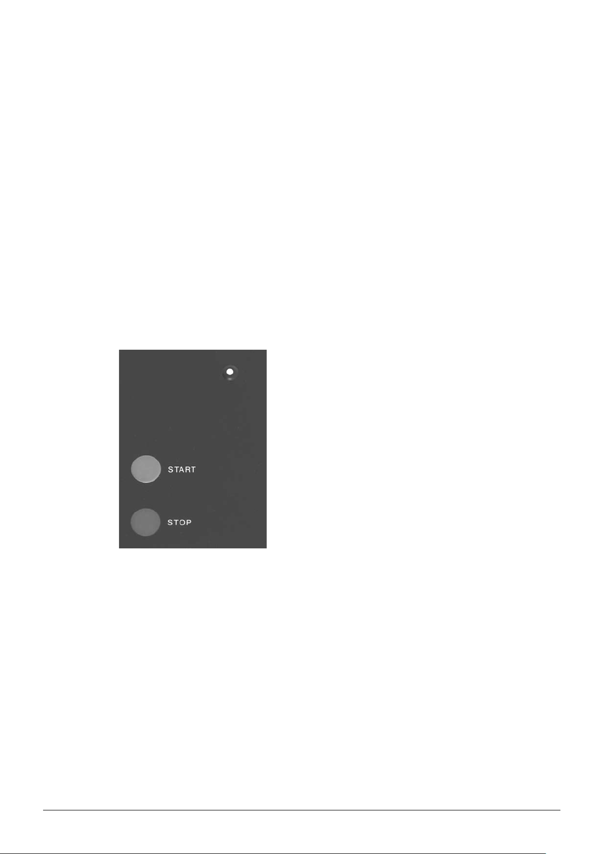
4.6.1 Operating panel
4 Description of function
Each measuring cell is equipped with an operating panel:
a
b
c
a LED
b START button
Operating panel of a measuring cell
The START button is used to start a measurement without using a PC keyboard.
The STOP button is used to stop a measurement without using a PC keyboard.
c STOP button
An LED informs the user about the current instrument state:
Red: Instrument is in error state
Green: Instrument is ready to use
Green flashing: Instrument is busy measuring
Yellow: Power is on but the instrument is not yet initialized by the NIRWare software
For a description of the LEDs at the handle of the fiber optic, see sections 4.6.15 and 4.6.17.
28 NIRFlex N-500 Operation Manual, Version F
Page 29

4.6.2 NIRFlex Solids
List of NIRFlex Solids add-ons
Max. number of samples per
sequence
Measurement based on
diffuse reflection
Measurement based on
transflectance
Measurement with petri
dishes
Measurement with vials - x - - -
Measurement of tablets - - x - -
Measurement using small
plastic bags
Internal reference x - - x x
External Reference x x x x x
Sample dimensions Spinner 34 mm
Spinner / Petri dish
add-on
1 6 10 1 1
x x x x -
x - - - x
x - - - -
- - - x -
Petri dish 100 mm
4 Description of function
Vial add-on Tablet add-on XL add-on Flow cell
Glass vials
10−15 mm
Tablets
5−10 mm
>0.3 ml
The NIRFlex Solids is the ideal configuration to measure solid samples like powders, pastes and
pellets in diffuse reflection mode. The measuring cell for solids allows the use of different add-ons for
specific sample containers.
The software automatically detects the type of add-on in use as soon as the corresponding application is started in the NIRWare Operator.
For a description of the add-ons to be used with the NIRFlex Solids, see section 4.6.3 to 4.6.8.
29 NIRFlex N-500 Operation Manual, Version F
Page 30

4 Description of function
7
5
4
3
1
a Detector
b Magnet sensor
c Status LED
d START button
e STOP button
f Internal reference
g Magnetic coding
h Sample
i Petri dish
Functional principle of the NIRFlex Solids
8
9
10
6
2
16
15
14
17
j Petri dish holder
k Rotary plate
l Motor
m Optic 1
n Light barrier
o Mirror 1
p Mirror 2
q Optic 2
11
12
13
4.6.3 Petri dish add-on for NIRFlex Solids
NIRFlex Solids with petri dish add-on
The NIRFlex Solids with the petri dish add-on is the ideal configuration to measure solid samples
in standard glass petri dishes. The petri dish add-on also enables to use a transflectance cover to
analyze liquids (e.g. solvents, milk, etc.). The transflectance technique is a good compromise for
customers, who only analyze liquids occasionally.
To carry out the reference measurement, the user has to place the External Reference (see also
section 5.10) onto the sample window.
30 NIRFlex N-500 Operation Manual, Version F
Page 31

4.6.4 Vial add-on for NIRFlex Solids
NIRFlex Solids with vial add-on
The NIRFlex Solids with the vial add-on is the ideal configuration to measure solid samples in glass
vials. This special add-on is equipped with 6 positions for sample vials with a diameter of
10−15 mm. Buchi provides one type of glass vials as an optional accessory for this specific add-on.
This built-in External Reference is measured automatically without any interaction of the operator.
A measurement sequence consists of a measurement of the reference and afterwards the measurement of the sample positions (1−6), which have been pre-defined in the NIRWare Operator. The
actually measured spectrum is set against the last measured reference.
4 Description of function
4.6.5 Tablet add-on for NIRFlex Solids
NIRFlex Solids with tablet add-on
The NIRFlex Solids with the tablet add-on is the ideal configuration to measure tablets in diffuse reflection mode. This special add-on is equipped with 10 sample positions for round tablets with a diameter
between 5−10 mm.
This built-in External Reference is measured automatically without any interaction of the operator.
A measurement sequence consists of a measurement of the reference and afterwards the measurement of the sample positions (1−10), which have been pre-defined in the NIRWare Operator.
31 NIRFlex N-500 Operation Manual, Version F
Page 32

4.6.6 XL add-on for NIRFlex Solids
NIRFlex Solids with XL add-on
The NIRFlex Solids with the XL add-on is the ideal configuration to measure solid sample in undefined
sample containers, like bags, beaker glasses, etc.
The sample container is placed on the flat add-on directly over sampling window. The sample holder
will not rotate during the measurement.
To carry out the reference measurement, the user has to place the External Reference (see also
section 5.10) onto the sample window.
4 Description of function
4.6.7 XL add-on with iris aperture for NIRFlex Solids
The NIRFlex Solids with the XL add-on with iris aperture is the ideal configuration to measure solid
samples in bigger glass vials with an diameter of up to 39 mm. The sample holder will not rotate
during the measurement. To carry out the reference measurement, the user has to place the External
Reference (see also section 5.10) onto the sample window.
XL add-on with iris aperture
32
NIRFlex N-500 Operation Manual, Version F
Page 33

4.6.8 XL add-on for B+L sample cups for NIRFlex Solids
The NIRFlex Solids with the XL add-on for B+L (Bran+Luebbe) sample cups is the ideal configuration
to measure solid sample in the B+L closed cup. The sample holder will not rotate during the measurement.
NOTE
For reference measurement remove the B+L cup first. Place the centering ring and the External Reference onto the XL add-on and perform the measurement.
4 Description of function
XL add-on for B+L sample cups
4.6.9 External Reference for XL and petri dish add-on
External Reference
An External Reference is needed when the XL add-on or the petri dish add-on is used on the NIRFlex
Solids.
The reference holder is designed with an opening to insert the External Reference into the correct
position.
NOTE
The reference holder is needed with the petri dish add-on only.
33 NIRFlex N-500 Operation Manual, Version F
Page 34

4.6.10 Spinner add-on
NIRFlex Solids in combination with the Spinner add-on is the ideal configuration to measure smaller
solid samples whereas the volume of a petri dish is too big. This add-on can also be used with a
transflectance cover to analyze liquids (e.g. solvents or milk). The transflectance technique is suitable
for customers, who analyze liquids occasionally.
4 Description of function
Spinner add-on
Cuvettes (i.e. Hellma cuvette) or glass vials with a diameter of 34 mm can be used as sample vessel in
the motor-driven Spinner. For reference measurement the Spinner can hold the External Reference.
4.6.11 Flow-cell adapter add-on
The NIRFlex Solids with flow-cell adapter add-on is the ideal configuration to measure liquids (e.g.
solvents and milk.) in a quartz flow-through cuvette with 1 mm pathlength.
Flow-cell adapter add-on
To connect the flow-cell, silicone tubes with 4 mm inner and up to 7 mm outer diameter can be used.
External referencing requires a clean and dry flow-cell. In some applications, referencing can also be
done with measurement solvent in the flow-cell.
34 NIRFlex N-500 Operation Manual, Version F
Page 35

4.6.12 NIRFlex Solids Transmittance
NIRFlex Solids Transmittance
It is a major request described in the pharmacopoeias to ensure consistency of dosage units; each
unit in a batch should have active ingredient content within a narrow range around the label claim.
Traditionally these analyses are made using HPLC determining only the active content, which is time
consuming and very costly. The speed, efficiency, and cost situation can be very much improved by
NIR spectroscopy.
4 Description of function
3
4
5
2
6
1
14
15
9
8
7
16
13
12
11
10
a Aperture 3 mm
b Sample
c Detector
d Optic 3
e Sample plate
f Magnetic coding
g Magnetic sensor
h Light barrier
Functional principle of NIRFlex Solids Transmittance
i Stepper motor
j Optic 1
k Aperture
l Mirror
m Optic 2
n Status LED
o START button
p STOP button
35 NIRFlex N-500 Operation Manual, Version F
Page 36

4 Description of function
Transmission measurements offer the advantage of collecting the information from the entire cross
section of the samples. This is ideal, especially for coated or multilayer tablets. NIRFlex N-500 is optimized for transmission measurements of solid dosage forms, like tablets or capsules.
a
b
a Detector b Sample position
Sensor position and beam path
4.6.13 Sample plates for the NIRFlex Solids Transmittance
The autosampler accepts up to thirty samples with a diameter
of 4 to 12 mm maximum.
The picture shows an example of a 30-place sample plate.
For samples larger than 12 mm up to 30 mm, 10-place sample
plates are available.
The picture shows an example of a 10-place sample plate.
The picture shows the 10-place sample plate with iris aperture
for method development.
36 NIRFlex N-500 Operation Manual, Version F
Page 37

4 Description of function
The picture shows the SST sample plate.
The picture shows an examle of a 30-place sample plate for
hard gelatin capsules.
Sample plates of the NIRFlex Solids Transmittance
4.6.14 NIRFlex Liquids
NIRFlex Liquids
The NIRFlex Liquids is the ideal configuration to measure liquids like solvents, oils, etc. in transmission
mode using glass cuvettes. The NIRFlex Liquids enables quantitative and qualitative analyses with
thermostated conditions of the samples (from room temperature plus 10 °C up to
65 °C.
The NIRFlex Liquids can accommodate up to six cuvettes with pathlengths up to 10 mm.
Current and set temperatures are displayed in the user interface.
37 NIRFlex N-500 Operation Manual, Version F
Page 38

4 Description of function
6
7
5
4
15
3
2
1
a STOP button
b START button
c Status LED
d Detector
e Optic 2
f Ventilation
g Heating
h Motor
Functional principle of the NIRFlex Liquids
14
8
9
10
11
12
13
i Optic 1
j Mirror
k Aperture
l Light barrier
m Magnetic coding
n Magnet sensor
o Reference position
38 NIRFlex N-500 Operation Manual, Version F
Page 39

4.6.15 NIRFlex Fiber Optic Solids
NIRFlex Fiber Optic Solids
The NIRFlex Fiber Optic Solids is the ideal configuration to measure solid samples in their original
container. The reflection probe operates with a fiber bundle.
The reflection probe can accommodate a transflectance adapter to analyze liquids as well (e.g.
solvents, milk, etc.).
The transflectance technique is a good compromise for customers, who only analyze liquids occasionally.
The handle is equipped with a remote control for initiating the measurements remotely and displaying
the results using LEDs on the handle.
The LEDs at the handle of the fiber optic probe indicate the status of the system and the results of the
prediction in routine operation.
4 Description of function
Applications without calibration (just measuring spectra, e.g. acquisition of calibration spectra)
- green LED flashing measuring
- green LED on measurement finished
red LED on green LED on message on monitor
Application with calibration (routine use for predictions)
- green LED flashing measuring
red LED on green LED on message on monitor
- green LED on result conforms
red LED on - result does not conform
Because the fiber optic probe is used at a certain distance from the spectrometer, the length of the
fiber optic cables between the measuring cell (spectrometer) and the probe tip is about 2 m
(3 and 5 m versions are available as well).
39 NIRFlex N-500 Operation Manual, Version F
Page 40

4 Description of function
6
9
10
5
11
12
13
14
7
4
8
3
2
1
18
16
17
15
a Magnet sensors
b LEDs: OK, not OK
c START button
d Handle
e Fiber bundle
f Electrical connections probe
g Light barrier
h Holder for fiber optic
i Internal reference
Functional principle of the NIRFlex Fiber Optic Solids
j Optic 3
k Detector
l Motor
m Optic 1
n Optic 2
o Directly reflected rays are invisible for the fiber optic
p Transflectance adapter
q Magnet
r External Reference
40 NIRFlex N-500 Operation Manual, Version F
Page 41

4.6.16 Transflectance adapter for NIRFlex Fiber Optic Solids
The transflectance adapter is an optional accessory for the NIRFlex Fiber Optic Solids and enables to
measure liquid samples, pastes and transparent films.
The transflectance measurement principle is a combination of transmission and diffuse reflection: The
light coming from the optical fibers penetrates the liquid sample in the gap between the probe window
and the transflectance adapter window (½ pathlength), is diffusely reflected at the white standard layer
behind the adapter window, passes the sample liquid in the gap a second time and goes back into
the optical fibers.
The transflectance adapter is suitable for the analysis of viscous, non-agressive liquids. Thanks to the
reproducible, adjustable pathlength it is suitable both, for the meausurement of slightly and of strongly
absorbing samples.
The transflectance technique is a good compromise for customers, who only analyze liquids occasionally.
As the measurements are carried out in the original sample containers, the probe head needs to be
dipped into the sample.
4 Description of function
Transflectance adapter
4.6.17 NIRFlex Fiber Optic Liquids
NIRFlex Fiber Optic Liquids
The NIRFlex Fiber Optic Liquids is the ideal configuration to measure liquid samples in their original
container.
The transmission probe operates with monofibers.
As the measurements are carried out in the original sample containers, the probe head needs to be
dipped into the samples.
The handle is equipped with a remote control for initiating the measurements remotely and displaying
the results using LEDs on the handle.
41 NIRFlex N-500 Operation Manual, Version F
Page 42

4 Description of function
The LEDs at the handle of the fiber optic probe indicate the status of the system and the results of the
prediction in routine operation.
Applications without calibration (just measuring spectra, e.g. acquisition of calibration spectra)
- green LED flashing measuring
- green LED on measurement finished
red LED on green LED on message on monitor
Application with calibration (routine use for predictions)
- green LED flashing measuring
red LED on green LED on message on monitor
- green LED on result conforms
red LED on - result does not conform
Because the fiber optic probe is used at a certain distance from the spectrometer, the length of the
fiber optic cables between the measuring cell (spectrometer) and the probe tip is about 2 m (special
versions with longer fiber optic cables are available on request).
6
9
10
5
11
12 13
7
14
4
8
3
2
1
a Protection cover
b LEDs: OK, not OK
c START button
d Handle
e Monofiber fiber optic 2 m
f Electrical connections
g Light barrier
Functional principle of the NIRFlex Fiber Optic Liquids
h Holder for fiber optic
i Internal reference
j Optic 3
k Detector
l Motor
m Optic 1
n Optic 2
42 NIRFlex N-500 Operation Manual, Version F
Page 43

4.6.18 NIRFlex Fiber Optic SMA
The NIRFlex Fiber Optic SMA is the ideal configuration to measure both, liquids and solids with
external accessories. The SMA-cell can be used to connect mono or multi fibers via its two SMA
connectors. Laboratory and immersion process probes in transmission or diffuse reflection mode as
well as flow-through cells can be attached.
4 Description of function
NIRFlex Fiber Optic SMA
NOTE
Glas fibers have to be handled with care. Do not bend, pull or twist the fibers! Follow the supple-•
mentary instructions of the fiber and accessories. See also section 5.8!
Depending on the application, distances of up to 100 m can be realized.•
External referencing has to be perfomed with clean and dry accessory!•
43 NIRFlex N-500 Operation Manual, Version F
Page 44

5 Putting into operation
This section describes how the instrument is installed and gives instructions on initial startup.
To avoid damage by condensate moisture, special attention is needed when the instrument was delivered at cold temperatures. Do not remove the instrument from its plastic bag for at least two hours to
let the instrument acclimatize to the ambient temperature!
5 Putting into operation
Risk of instrument damage by moisture condensate.
NOTE
Inspect the instrument package for damage immediately after delivery. If necessary, prepare a status
report immediately and inform customer and your local Buchi representative. Keep the original
packaging for future transportation.
5.1 Transportation lock
The NIRFlex N-500 is equipped with a mechanical transportation lock to avoid damage of the interferometer during transportation and shipping by shocks and vibrations. The transportation lock is in
“Locked” position at initial delivery.
After system installation and prior use, the interferometer has to be unlocked! See following section for
information about unlocking.
Risk of instrument damage at use with engaged transportation lock.
NOTICE
Let the instrument sufficiently acclimatize before unpacking•
NOTICE
Disengage the transportation lock prior use•
Keep shocks and vibrations away•
44 NIRFlex N-500 Operation Manual, Version F
Page 45

5 Putting into operation
!
In the front of the main cover of NIRFlex N-500
there is an opening which is hidden behind the
“Locked - Unlocked” shield. For the operation
1
of the transportation lock pull out the shield first.
Insert the torx screwdriver supplied with the
instrument and flip the locking mechanism by
moving it to the side.
2
a LOCKING movement
b Output window of the interferometer
3
c UNLOCKING movement
The installation position of the shield depends
on the locking status of the transportation lock.
The label of the shield in this image indicates a
locked transportation lock.
Operating the transportation lock
5.2 Requirements concerning the installation site
Basic installation conditions
DANGER
Death or serious injuries by use in explosive environments.
Do not store or operate the instrument in explosive environments•
Remove all sources of flammable vapors•
Do not store chemicals in the vicinity of the device•
45 NIRFlex N-500 Operation Manual, Version F
Page 46

5 Putting into operation
The instrument must be installed:
indoor only with a clearance of 15 cm minimum to walls and any other objects•
without being exposed to heating or cooling source (e.g. direct sunlight or air conditioning)•
with the transportation lock in unlocked posit• ion (see previous section)
on a stable and horizontal position•
NOTE
Because of its weight it is recommended to carry the instrument with two persons.
If the instrument is installed on a laboratory cart, the cart should have large, soft wheels (approx. 10
cm diameter) for better shock absorption at transport on even floors.
To avoid damage by condensate moisture, special attention is needed when the instrument is moved
between environments with bigger temperature difference! When moving the instrument from a colder
to a warmer environment, let it acclimatize to the ambient temperature before switching it on!
Risk of instrument damage by moisture condensate.
The electric plug on the measuring cell is only designed to plug-in the measuring cells. Do not connect
any other item.
The spectrometer must be placed onto a clean, level and stable support. It is recommended to set up
the spectrometer so that it is easily accessible from all sides.
The spectrometer is normally operated from the front. Make sure that ergonomic and back-friendly
operation is insured.
NOTICE
Let the instrument sufficiently acclimatize at relocation•
5.3 Electrical connection requirements
After the pre-installation procedure (all internal connections have been established and transportation
lock is in unlocked position) has been completed successfully, the power plug of the NIRFlex N-500
can be connected to mains.
The used mains circuit has to:
provide the voltage that is given on the type plate of the instrument.•
be able to handle the load of the connected instruments.•
be equipped with adequate fuses and electrical safety measures, in particular proper grounding.•
See also technical data of all components regarding the different minimum system requirements!
Risk of instrument damage by wrong mains supply.
46 NIRFlex N-500 Operation Manual, Version F
NOTICE
External mains supply must meet the voltage given on the type plate•
Check for proper grounding•
Exchange defective cabling instantly•
Page 47

NOTE
To cut the power in case of an emergency by unplugging, the instrument or any other item must •
not block the mains plug! The plug must be able to be pulled out instantly at all time.
Additional electrical safety measures such as residual current breakers may be necessary to meet •
local laws and regulations!
External power switches (e.g. emergency stop switches) must meet IEC 60947-1 and IEC •
60947-3 requirements. Such devices must be clearly labeled and accessible at any time.
External connections and extension lines must be provided with a grounded conductor lead •
(3-pole couplings, cord or plug equipment). All used power cords must meet the input power
requirements.
5.4 Installing the instrument
To install the instrument, proceed as follows:
Connect the NIRFlex N-500 to the PC using the supplied Ethernet cable.•
Connect the mains cable to the socket.•
Switch on the NIRFlex N-500 via the main switch on the rear of the instrument.•
Start the PC, and install the NIRWare software.•
Set up the communication between NIRFlex N-500 and the PC.•
5 Putting into operation
5.4.1 Setting up the Ethernet communication
The NIRFlex N-500 is equipped with one Ethernet (LAN) socket at the rear side.
LAN
LAN settings of the NIRFlex N-500
The primary network connector (LAN1) is predefined for direct communication to a PC.
Standard configuration of the Spectrometer:
Static IP-address 192.168.1.1•
Subnet mask 255.255.255.0•
NOTE
The default IP-address of the spectrometer can be changed to a customer specific static •
IP-address provided by the local IT. This configuration is done within the Service Tools and
described in the NIRWare Online Help and the corresponding PDF-file.
The spectrometer‘s IP-address can be reset to default (192.168.1.1) by pushing and holding •
both, START and STOP button, at the measuring cell during the power-up procedure of the
NIRFlex N-500 for about 50 seconds.
47 NIRFlex N-500 Operation Manual, Version F
Page 48

LAN setup of the PC
To establish communication, set up the IP of the connected PC in accordance to the local network
environment or via direct link as listed below.
IP-configuration of the connected PC (direct link):
Static IP-address 192.168.1.2•
Subnet mask 255.255.255.0•
5.4.2 Network integration
There are various possibilities how the NIRFlex N-500 can be installed and used.
In the following, two examples are given:
5 Putting into operation
All data on one PC via direct link
The PC with the NIRWare database is directly connected to the NIRFlex N-500.
All data remain on that specific PC.
NIRWare database on central company server via indirect link
The NIRWare database runs on a central company server. The Administrator has access to the database on that server. The data measured by the Operator are collected on the database of the central
company server.
NOTE
Other setups i.e. with the NIRFlex N-500 directly attached to a local network can also be realized.
48 NIRFlex N-500 Operation Manual, Version F
Page 49

5.5 Installing the measuring cells
All different measuring cells are provided with a plug connection.
Installing a measuring cell
To install a measuring cell, proceed as follows:
Place the measuring cell vertically into the provided space.•
Carefully applying pressure to the measuring cell, make sure that the plug connection catches.•
Make sure it is seated well by means of the centerning pins at the NIRFlex N-500. •
Subsequently, fasten the measuring cell with the fixating screw at the bottom of the NIRFlex N-500. •
5 Putting into operation
NOTE
When using the NIRFlex Solids Transmittance cell, put the sample plate onto the cell by inserting the
central hole into the shaft. The guiding pin must be inserted into the corresponding hole (next to the
handle).
Risk of measurement interruption and data errors by communication loss.
NOTICE
Fixate the measuring cell to the basic instrument using the fixing screw at the bottom plate of •
the instrument.
49 NIRFlex N-500 Operation Manual, Version F
Page 50

5.6 Installing the cover of the NIRFlex Solids Transmittance
b
5 Putting into operation
a
Insert the tilted cover a and hook its left hinge onto to the bushing pin (hinge counterpart) at the rear
left hand side of the measuring cell. Tilt the cover back into a straight position b.
c
Keep the right hinge of the cover in a matching position with the bushing screw. Fasten the screw c
with a few turns (the screwdriver is part of the scope of delivery). Open and close the cover several
times to verify the correct installation.
Risk of mechanical damage at the hinges of the top cover.
50 NIRFlex N-500 Operation Manual, Version F
NOTICE
Keep the top cover closed when the measuring cell is not installed•
Carefully open and close the top cover to avoid mechanical stress at the hinges•
Page 51

Additional handling instructions
5 Putting into operation
Install the measuring cell with the top cover •
closed to avoid mechanical stress at the
hinges!
Keep the top cover closed during a measure-•
ment to keep out scattered ambient light.
Open and close the top cover carefully.•
At closing:
A small bumper avoids hard impact to the cover.
At opening:
Do not release the top cover until it is in fully open
position! The hinges might break-away.
Additional handling instructions
5.7 Preparing the transflectance adapter
5.7.1 Adjusting the pathlength of the transflectance adapter to the probe head
When you receive the transflectance adapter with a new instrument:
When you receive your transflectance adpater together with a new NIRFlex N-500 instrument, the
pathlength has already been adjusted to the probe head by the manufacturer.
When you receive the transflectance adapter as additional accessory for an instrument already
installed:
As the probe head dimensions may vary slightly you need to adjust the transflectance adapter to the
probe head when you receive it as additional accessory for an instrument already installed.
A correct adjustment is necessary for the portability of spectra.
To adjust the pathlength of the transflectance adapter to the probe head, the spacer ring 1 mm is
used. The other spacer rings have been manufactured to fit accordingly.
Normally, the transflectance adapter is delivered with the adjustment ring and the spacer ring 1 mm
mounted. If this is the case, proceed with section 5.7.2.
51 NIRFlex N-500 Operation Manual, Version F
Page 52

If this is not the case, proceed as follows:
5 Putting into operation
Slide the adjustment ring over the transflectance sleeve and •
turn it on the thread as far as possible.
Now slide the 1 mm spacer ring over the transflectance •
sleeve, so that the pin on the inner surface of the spacer ring
fits into the groove in the adjustment ring.
Place the 1 mm spacer disk in the center of the transflec-•
tance adapter window.
Slide the transflectance adapter over the probe head and •
orient it so that the pin at the probe head is pushed into the
groove of the spacer ring.
Push the transflectance sleeve upwards until the spacer disk •
a
NOTE
It is very important that the spacer disk is located on the window center, otherwise it could get stuck
between the metal edges during the adjustment procedure, damage the windows and fail to indicate
the correct distance between probe and adapter window.
seats solidly between the transflectance adapter window
and the probe window and exactly determines the distance
between those two.
Tighten the retaining screw • a.
52 NIRFlex N-500 Operation Manual, Version F
Page 53

5 Putting into operation
Now turn the adjustment ring upwards until there is no •
clearance between the adjustment ring and the spacer ring
anymore.
Tighten one of the three socket screws on the adjustment •
ring by means of the allen key.
Loosen the retaining screw and remove the transflectance •
adapter from the probe head.
Now tighten the remaining two socket screws on the adjust-•
ment ring and the socket screw on the spacer ring.
Adjusting the pathlength
NOTE
The socket screw may be replaced by one of the knurled screws for easier exchange.
The pathlength of the transflectance adapter is now adjusted to this specific probe head, so that both
form a functional unit. The pathlength now matches the engraving of the spacer ring in each case and
no additional adjustment is necessary, when you change from one spacer ring to another.
5.7.2 Exchanging the spacer ring
To exchange the spacer ring in order to work with another pathlength, proceed as follows:
Loosen the screw on the spacer ring by means of the allen •
key.
Remove the spacer ring.•
Take the new spacer ring you want to operate with, slide it •
over the transflectance adapter and tighten the screw.
Exchanging the spacer ring
5.7.3 Installing the transflectance adapter to perform measurements
To perform a measurement, slide the transflectance adapter over the probe head and orient it so that
the pin at the probe head is located in the groove of the spacer ring. Tighten the retaining screw.
NOTE
When performing measurements, make sure that there are no air bubbles in the measuring gap
(pathlength) between probe and adapter window by carefully moving the probe head in the sample.
When you do not perform any measurements with the transflectance adapter, store it in the plastic
box.
53 NIRFlex N-500 Operation Manual, Version F
Page 54

5 Putting into operation
5.8 Installing measurement equipment to the NIRFlex Fiber Optic SMA
To install the instrument, proceed as follows:
left connector = short spring
right connector = long spring
To mount the SMA-adapter onto the optical
fiber cable:
Put the spring onto the fiber connector •
and secure the end of the connector with
the threadened spacer nut.
NOTE
The spring must be freely movable after
installation! Fasten the spacer nut handtight
only!
Insert the optical fiber cable.•
Place it into the cable-slot of the stress •
relief and swivel the stress relief to match
the screw heads at the SMA socket.
Push the stress relief against the spring •
of the optical fiber cable and swivel it into
vertical position.
Fasten the two fixating screws of the •
stress relief hand-tight.
Fixate the optical cable with cable ties.•
54 NIRFlex N-500 Operation Manual, Version F
Page 55

5.9 Starting up the system
An automatic initialization process starts as soon as the NIRFlex N-500 and the PC are started up.
The main components of the spectrometer are identified and its basic functions are checked during
that initialization process, e.g. lamp unit, standard wheel, laser unit, measuring cell. The time needed
for initialization is about 60 seconds.
5.9.1 System Suitability Test
The
System Suitability Test (SST) serves as an internal functionality and performance test of the
spectrometer. It is recommended to run an SST after each restart of the NIRFlex N-500 to monitor and
verify the system performance.
The following SST values are tested:
Internal system temperatures (e.g. Laser, interferometer, detectors) •
Linearity•
Signal-to-noise ratio•
Wavenumber stability•
5 Putting into operation
At the end of each SST a report protocol will be generated. The test results are compared to values ex
factory and inform the user about the system condition.
➥ The report data are stored in the internal database for service and quality control.
NOTE
The time between two SST requests can be set with the NIRWare Application Designer. The recommended standard value between two tests is 24 hours, a test-run takes approximately 5 min. Test
results can be exported and stored in XML-format, e.g. for service purpose.
If the instrument is used in continuous operation (e.g. several days of ON-time), a longer checking
interval might be suitable. However, frequent tests should be performed to minimize the risk of erroneous measurement.
5.9.2 Temperature tests in detail
The system is equipped with numerous temperature sensors. Individual lower and upper temperature
limits are predefined for each sensor.
➡ To pass this test, all actual temperature values must be within the limits.
NOTE
Mind the ambient temperature data as listed in section 3, Technical data.
If temperature is too low • ➡ let system warm up sufficiently
If temperature is too high • ➡ clean filters and provide sufficient airflow
5.9.3 NIR linearity test
With this test the linearity of the intensity scale of the spectrometer is being tested. The absorbance of
a set of five gray filters in the standard wheel is measured sequentially and compared with reference
values.
➡ To pass this test, all absorbance factors must be within the tolerance.
55 NIRFlex N-500 Operation Manual, Version F
Page 56

5.9.4 Signal-to-noise ratio determination
With this test the ratio of signal power to noise power is determined. A high flux (maximum intensity)
and a low flux (10% intensity) beam is being analyzed for a number of wavenumber intervals.
➡ To pass these tests, the average and the minimum values must be within the tolerance.
5.9.5 Wavenumber stability test
The wavenumber stability of the system is checked with the PMMA reference plate of the reference
wheel. One absorption peak of the transmission spectrum is being analysed and compared to its
reference value.
➡ To pass this test, the wavenumber accuracy must be within the tolerance.
5.9.6 SST with NIRFlex Solids Transmittance
The SST for the NIRFlex Solids Transmittance is extended in comparison to the SST for the other
measuring cells. It is performed with the special SST sample plate, which is provided with every
NIRFlex Solids Transmittance, and the internal standard wheel.
Wavelength accuracy is measured in transmittance using a mixture of Rare Earth Oxides.
Noise measurements are performed with open beam and with the 5 mm white standard disk both
high and low flux.
The linearity tests are performed for open beam, 1 mm and 5 mm white standard disks together with
the grey filters of the internal standard wheel covering the complete photometric dynamic range.
5 Putting into operation
5.10 Reference measurements
Frequent reference measurements compensate for environmental effects, which might influence the
spectra. Each measuring cell offers a possibility for the reference measurement, the External Refer-
ence. Some measuring cells additionally offer the possibility of an internal referencing.
External Reference
In order to measure the transmittance or the reflectance of a sample, the measured intensity spectrum
of the sample is divided by a reference spectrum. This reference spectrum is either recorded without a
sample (in case of transmittance) or with a white standard in the sample position (reflectance). We call
this an External Reference. An External Reference is always required.
Internal reference
While the acquisition of an External Reference can be automated in some cases (NIRFlex Liquids,
NIRFlex Solids Transmittance, Vial and Tablet add-on for NIRFlex Solids), in other cases the measurement of an External Reference requires user interaction (petri dish and XL add-on for NIRFlex Solids,
NIRFlex Fiber Optic Solids, and NIRFlex Fiber Optic Liquids). In these cases internal referencing is
used to minimize the need for external referencing and user interaction.
Internal and External Reference measurements provided by the measuring cells/add-ons
Measuring cell / Add-on Internal reference External Reference
NIRFlex Solids with petri dish add-on x manually
NIRFlex Solids with vial add-on - built-in
NIRFlex Solids with tablet add-on - built-in
NIRFlex Solids with XL add-on - manually
NIRFlex Solids with Flow Cell add-on - manually
56 NIRFlex N-500 Operation Manual, Version F
Page 57

5 Putting into operation
Spectrum =
sample
ext. reference
Spectrum =
sample (recent) / int. reference (recent)
ext. reference (old) / int. reference (old)
Internal and External Reference measurements provided by the measuring cells/add-ons
Measuring cell / Add-on Internal reference External Reference
NIRFlex Solids with Spinner add-on - manually
NIRFlex Solids Transmittance - built-in
NIRFlex Fiber Optic Solids x manually
NIRFlex Fiber Optic Liquids x manually
NIRFlex Liquids - built-in
NIRFlex Fiber Optic SMA
(+ individual accessories)
without internal reference:
with internal reference:
x manually
For more information on the reference measurements, see also section 6.
57 NIRFlex N-500 Operation Manual, Version F
Page 58

6 Operation
This section describes how to start a measurement and how to prepare a reference measurement and
gives recommendations on possible applications of the instrument.
6 Operation
Risk of instrument damage at use with engaged transportation lock.
NOTICE
Disengage the transportation lock prior use•
Keep shocks and vibrations away•
6.1 General recommendations for measuring solids
The calibration wavelength range with a standard fiber optic probe goes from 4500 to 10000 cm-1.
For quantitative applications the fiber optic probe should be fixed.
Hygroscopic samples show temperature dependency. The samples should either be measured at a
constant temperature or the temperature influences must be considered during calibration.
Coarse grained samples must be possibly milled before carrying out the measurement.
Number of scans: Qualitative calibration: 4−16 (max. 32); quantitative calibration: 16−32;
granules: 64. The spectral range of the NIRFlex Solids Transmittance is limited to 6000 cm-1. The
number of scans should be 64 by default.
General recommendations for measuring solids
Sampling option Substance External Reference measurement Comment
NIRFlex Fiber Optic Solids Homogenous powder
(qualitative) solids with
flat surface
NIRFlex Solids with petri dish
add-on
NIRFlex Solids with XL add-on Powder in containers
NIRFlex Solids with vial
add-on
NIRFlex Solids with Spinner
add-on
NIRFlex Solids Transmittance tablets, capsules,
Powder (quantitative)
granules
pellets
Powder in small glass
vials
Powder (quantitative),
granules
powders in small
plastic cups
White standard in the
reference cap
White standard in a reference holder
White standard on XL
add-on
White standard in vial
add-on
White standard in a reference holder
Open beam (reference
position in sample plate)
Make sure that there is
enough sample in the dish so
that all the light is reflected
by the sample
Make sure that there is a
constant bulk density, a
constant sample container
quality and a reproducible
container position
58 NIRFlex N-500 Operation Manual, Version F
Page 59

6.2 General recommendations for measuring liquids
For sample measurements with the NIRFlex Liquids, make sure that the cuvettes are placed in the
direction of the centre of the cuvette holder. This is important to ensure optimal heat transfer to the
sample.
The calibration wavelength range with glass cuvettes goes from 4000 to 10000 cm-1.
The useable wavelength range for measurements with a fiber optic probe is 4500 – 10000 cm-1.
Temperature differences can cause a spectral shift. The samples should either be measured at a
constant temperature or the temperature influences must be considered during calibration.
Avoid air bubbles.
Number of scans: Qualitative calibration: 4−10; quantitative calibration: 16−32 (max 64)
General recommendation for measuring liquids
Sampling option Substance External Reference measurement Comment
NIRFlex Liquids Transparent liquids Built-in External Reference
(air)
NIRFlex Fiber Optic Liquids Transparent liquids
aggressive, trans-
parent liquids
NIRFlex Solids with petri dish
add-on and transflectance cover
Clear liquids, turbid
liquids
Clean probe head Max. temperature
Empty petri dish with
transflectance cover
6 Operation
1, 2, 5, 10 mm
cuvette with spacer
150 °C
avoid air bubbles
Avoid air bubbles
NIRFlex Solids with flow-cell
adapter add-on
NIRFlex Solids with Spinner add-on
and transflectance cover
NIRFlex Fiber Optic Solids with
transflectance adapter
6.3 Starting a measurement
The spectrometer needs a warm-up time of approx. 15 min. The lamp and the laser within the instrument will be switched on as soon as the NIRWare software is running.
When the instrument has warmed up and the sample is presented to the instrument, you can start the
measurement.
Generally, you have two possibilities to do so:
Press the START button at the measuring cell.1.
Click the Start icon (green arrow) in the NIRWare Operator.2.
NOTE
When you are working with the NIRFlex Fiber Optic Solids or NIRFlex Fiber Optic Liquids probe, you
can also use the remote button on the handle to start a measurement.
Clear liquids, turbid
liquids
Clear liquids, turbid
liquids
Clear liquids, turbid
liquids
Clean flow cell Avoid air bubbles
Empty cuvette with transflectance cover
Clean probe head Make sure there
Avoid air bubbles
are no air bubbles
in the gap
59 NIRFlex N-500 Operation Manual, Version F
Page 60

6.4 NIRFlex Solids
6.4.1 Reference measurement for the Petri dish add-on
A pop-up will remind the operator to measure the External Reference as soon as a certain time
window (predefined in the Application Designer) has passed.
A new External Reference is mandatory
when a new application is selected•
when an add-on or a new measuring cell is selected•
every time the software is restarted•
To measure the External Reference, proceed as follows:
Remove any sample from the add-on and ensure that the glass window is clean.•
Make sure that the bottom side of the External Reference and its holder is clean.•
Place the holder with the External Reference on the petri dish add-on and measure the External •
Reference.
6 Operation
6.4.2 Reference measurement for the XL add-on
A pop-up window will remind the operator to measure the External Reference as soon as a certain
time window (predefined in the Application Designer) has passed.
A new External Reference is mandatory
when a new application is selected,•
when an add-on or a new measuring cell is selected, or•
every time the software is restarted.•
To measure the External Reference, proceed as follows:
Remove any sample from the add-on and ensure that the sample glass window is clean.•
Make sure that the bottom side of the External Reference and is clean.•
Place the External Reference on the XL add-on, rotate it until the mark on the reference is next to •
the hole in the XL add-on, and measure the External Reference.
6.5 NIRFlex Solids Transmittance
Diffuse transmission measurements are very demanding applications, because only a very small part
of the incident light is transmitted. Therefore care must be taken for good signal-to-noise ratio. The
design of the NIRFlex Solids Transmittance and its optimized detector ensure best performance.
NIRFlex Solids Transmittance uses a low energy source, which avoids any overheating of the samples
and therefore enables the analysis of temperature sensitive active ingredients. Emissions e.g. from
fluorescent tubes can cause artifacts in the sample spectrum. Therefore the cover of NIRFlex Solids
Transmittance must be closed during measurements.
Risk of incorrect measurement results by ambient light
60 NIRFlex N-500 Operation Manual, Version F
NOTICE
Keep the top cover closed during a measurement•
Page 61

6 Operation
Typical samples for the NIRFlex Solids Transmittance include tablets, hard gelatin capsules, powders
or soft gelatin capsules including semi-liquids or oily liquids, which requires a very high dynamic photometric range of the system. The design of the measuring cell takes this requirement into account.
Without any special settings the user will generate spectra with optimized signal-to-noise ratio for his
specific samples.
For reproducible and accurate results in tablet transmission measurements, it is essential to prevent
stray light caused by light passing around the side of the tablets. Therefore the sample plates are
individually customized in order to fit perfectly for your tablets and to ensure the optimal performance.
Additionally the sample plates exhibit a specially selected coating to prevent reflection and light
leakage.
All sample plates include an External Reference position. By default reference measurements are
performed automatically before every measurement sequence.
6.6 NIRFlex Liquids
System preparation
The liquid cell must reach a stable working temperature before a measurement can be performed. The
heat-up time depends on the ambient temperature.
Starting at standard ambient temperature of 25 °C the measurement cell needs:
approximately 15 minutes to stabilize at 35 °C.•
approximately 30 minutes to stabilize at 60 – 65 °C.•
Depending on the heat distribution and the positioning of the cuvettes the temperature difference
between probe and liquid temperature is about 2 °C at a measurement temperature of 65 °C.
Risk of damage at the coating of the sample plate
Risk of measurement errors by unsufficient heat-up time
NOTICE
Do not cleat the sample plate in a dishwasher•
Clean the sample plate with Ethanol and a soft, lint-free tissue•
NOTICE
Cuvettes and sample material must be completely heated-up at measurement•
NIRFlex Liquids measurement cell
61 NIRFlex N-500 Operation Manual, Version F
Page 62

6 Operation
!
CAUTION
Minor or medium burns by hot surfaces
Do not touch the cell chambers•
NOTE
The software does not prevent measurements in case of incorrect temperatures. The operator is
responsible, that the current temperature corresponds with the set temperature. A reproducible
temperature of the samples is crucial when carrying out measurements in transmission mode. The
heat-up time of the sample material must be sufficient to reach the measurement cell temperature.
Working with different types of cuvettes
For most of the applications running with the NIRFlex Liquids, the use of 2 mm cuvettes is recommended. However, the cell is designed to use 1, 5 and 10 mm cuvettes as well. If doing so, the
spacers, which fix the cuvettes in the measurement position, must be changed. A set of different
spacers is included in the scope of delivery.
For quadratic cuvettes :
No spacers are required.
For rectangular cuvettes:
All rectangular cuvette types must be installed
in pairs with a matching spacer!
The cuvette must be aligned to the turning •
hub (inner circle of the cell).
A matching spacer must be aligned to the •
outer circle of the cell.
Handling of different cuvette types
NOTE
Quartz glass cuvettes are recommended when working with the NIRFlex Liquids. Most plastic
cuvettes show a significantly higher light absorption rate which can reduce the determination
performance. This also has direct influence onto calibration and reproducibility. Make sure that the
radiated surfaces of the cuvettes are placed perpendicular to the beam of light.
62 NIRFlex N-500 Operation Manual, Version F
Page 63

!
Risk of fire by highly flammable materials
Do not insert highly flammable materials or samples into the measurment cell•
6.7 NIRFlex Fiber Optics
All fiber optics must be treated with special care to avoid breaks and other damages of the glass fibers
and optical surfaces! Cleaning should always be done manually with a soft, lint free damp cloth with
mild soapy water. Optical surfaces can be cleaned with Kimwipes.
WARNING
6 Operation
Risk of damage at the fiber optics
Do not bend the fiber optics to a radius smaller than 15 cm•
Do not overstrech or twist the fiber optics•
Do not expose the fiber optics to heavy impacts or punctual pressure•
Do not bring the fiber optics into contact with organic solvents, acids or alkaline solutions•
Do not bring the white standard into contact with furanes, acids and other oxidizing agents•
6.7.1 NIRFlex Fiber Optic Solids
The handle is equipped with a remote control for initiating the measurements remotely and displaying
the results using LEDs on the handle.
Because the fiber optic probe is used at a certain distance from the spectrometer, the length of the
fiber optic cables between the measuring cell (spectrometer) and the probe tip is about 2 m (special
versions with longer fiber optic cables are available on request).
Risk of damage at the white standard
Do not bring the white standard into contact with furanes, acids and other oxidizing agents•
NOTE
The software automatically detects the presence of a transflectance adapter but not the path-•
length in use, so make sure to use the appropriate pathlength.
It is not possible to start a reference measurement if the reference cap has not been detected by •
the system.
NOTICE
NOTICE
Reference measurement
For correct measurements and correct results, it is necessary to record a reference spectrum regularly.
For this purpose, use the reference cap. In order to avoid false results, the reference cap is detected
automatically if installed.
63 NIRFlex N-500 Operation Manual, Version F
Page 64

6.7.2 NIRFlex Fiber Optic Liquids
For most of the applications a pathlength of 1 or 2 mm is the best choice. Many samples will contain
water or alcohol, which cause strong NIR absorptions. Therefore for the standard NIRFlex Fiber Optic
Liquids a pathlength of 2 mm will be sufficient (special versions with other pathlengths are available).
For sample measurements with the NIRFlex Fiber Optic Liquids make sure that the quartz window in
the probe head is in full contact with the sample to be analyzed.
Despite its rugged design, the transmission probe requires careful treatment.
6.7.3 NIRFlex Fiber Optic SMA
This measurement setup is suitable for continuous online measurements. Special settings can be
found in the NIRWare manual.
NOTE
Respect handling and operation information provided by the manufacturer of your custom optics /
accessories.
6 Operation
64 NIRFlex N-500 Operation Manual, Version F
Page 65

7 Maintenance
!
!
This section gives instructions on all maintenance work to be performed in order to keep the instrument in good working condition. In addition to this, adjustment jobs the operator can carry out by
himself/herself are explained.
7 Maintenance and repairs
CAUTION
Risk of dangerous device status or defects and malfunctions when serviced by untrained personnel
Service and maintenance actions which require to open the device housing must be •
performed by trained personnel only
Switch off the device and disconnect the mains cable before any service, maintenance or •
cleaning
Do not touch live parts•
Close the housing before reconnecting the device to mains•
7.1 Cleaning
To avoid cross-contamination and germ dissemination (e.g. by bacteria) the operator is advised to
attend common laboratory biosafety measures in accordance the chosen application and environment. The “Laboratory Biosafety Manual” of the World Health Organization can be used as a practical
guidance.
7.2 Housing
Clean the housing with a soft, lint free damp cloth with mild soapy water. For hygienic reasons, use
surface disinfectant wipes in combination with similar disinfectant spray on alcohol basis. If the sample
window on top of the instrument is dirty, clean it with an antimicrobial wipe (e.g. Melisptol® wipes).
WARNING
Risk of cross-contamination and germ dissemination at use
Exchange filter regularly•
Keep the housing and the working area clean•
Keep all surfaces in contact with sample material clean and free of germs•
Use disinfectant to avoid germ dissemination•
Do not reuse sample material•
Risk of damage at the housing
65 NIRFlex N-500 Operation Manual, Version F
NOTICE
Do not use any objects for cleaning which might scratch the optical surfaces or add-ons•
Do not clean coated optical surfaces in a washer.•
Page 66

In order to avoid contamination by sample material between the measurements, clean the surfaces in
direct contact with the sample after each measurement.
NOTE
Switch off the NIRFlex N-500 and all directly connected eletronic devices i.e. monitors before •
cleaning the housing.
Avoid scratches on optical surfaces as they can influence a measurement!•
For coated optical surfaces, use abrasion-resistant precision cloths such as Kimwipes from •
Kimberly-Clark. Primary cleaning can be done with disinfectant wipes on alcohol basis.
Avoid fingerprints on any optical surface!•
7.2.1 Optical surfaces and probes
All optical surfaces must be handled with care i.e. must not be scrached, cleaned with unproper
cleaning medium. Do not apply excessive force to any part of the device or its accessories!
If the connectors for the measuring cell on the instrument are dirty, clean them with a soft cloth moistened with alcohol.
In order to avoid contamination by sample material between the measurements, clean the surfaces
in direct contact with the sample after each measurement. For this purpose, use abrasion-resistant
precision cloths such as Kimwipes from Kimberly-Clark. Loose dust can be removed by blowing with
clean and oil-free compressed air. If substances still adhere, you may additionally rinse the surfaces
with acetone or alcohol.
7 Maintenance and repairs
Due to the limited resistance of the adhesive between metal and quartz glass, the fiber optic probe
must not be in prolonged direct contact with organic solvents nor acids and alkaline solutions. Take it
out of the liquid directly after completing the scans.
To prevent contamination of the white standard reference make sure that it is always applied to a
clean measuring cell.
Risk of damage at the coating of the sample plate
7.2.2 Cleaning of the External Reference
For dependable reference measurements the External Reference and Transflectance adapter must be
clean and damage free.
sary precautions, rinse it with pure acetone. Make sure to remove all cleaning residue.
NOTICE
Do not cleat the sample plate in a dishwasher•
Clean the sample plate with Ethanol and a soft, lint-free tissue•
In case the External Reference is strongly contaminated despite the neces-
66 NIRFlex N-500 Operation Manual, Version F
Page 67

7 Maintenance and repairs
Risk of damage at the External Reference
After treating the External Reference with pure acetone, always make sure that the acetone adsorbed
by the reference material evaporates completely.
For this purpose, you can place the External Reference in an oven for a few minutes at a maximum of
60 °C.
The reference material adsorbs oils and fats.
7.2.3 Cleaning of the Transflectance adapter
The transflectance adapter should be cleaned regularly after each measurement in order to avoid a
sample cross contamination during the next measurement.
To clean the transflectance adapter you can rinse it with solvents suited for use with the materials of
the adapter and probe (stainless steel, quartz glass, fluorine rubber). After rinsing, dry the adapter
thoroughly and carefully inspect it for remaining contaminations.
Suited cleaning solvents are water, acetone, and alcohols.
NOTICE
Do not drop the External Reference•
Do not scratch the surface•
Never bring it in contact with hard objects.•
Do not use any cleaning media with abrasive character which might scratch the surface.•
Do not use item for reference measurement when damaged or scratched. •
Do not use any compressed air for blowing off dirt from the External Reference, as it often •
contains oil and is not sufficiently pure.
Risk of damage at the Transflectance adapter
67 NIRFlex N-500 Operation Manual, Version F
NOTICE
Do not bring any part of the adapter into contact with Furanes, acids and other oxidizing •
agents
Page 68

NOTE
Exact cleaning procedures tailored to the indiviudal sample composition have to be developed by •
the customer.
When you analyze liquids of medium or high viscosity, sample residues may accumulate in the •
measuring gap and all other gaps between the adapter and the probe. In this case, remove the
transflectance adapter from the probe head to clean it thoroughly in order to avoid a sample
cross-contamination during the next measurement.
7.3 Advanced testing with NIRWare Automatic Diagnose
In addition to the SST NIRWare 1.x includes the NIRWare Automatic Diagnose (NADIA). NADIA is a
tool which enables Buchi service personnel to judge the condition of the NIRFlex N-500 or to do a
performance check of the instrument as part of a service contract.
To start NADIA select Start > Programs > Buchi NIRSolutions > NIRWare > Nadia
7 Maintenance and repairs
Close the NIRWare Operator before starting NADIA. The Control System Service must be stopped
during the test. NADIA will prompt you for permission to stop the Control System Service, if it detects
a running Control System Service.
Click ‘Start’ to execute the Nadia test and follow the instructions on the screen.
Once the test is finished, the following information is displayed:
Test result Nadia
The result is saved in an *.xml file, which is stored in the folder shown below:
68 NIRFlex N-500 Operation Manual, Version F
Page 69

MyNadiaFiles
7 Maintenance and repairs
Send this file to your customer service organisation for evaluation. To archive the file, copy it to a
different folder.
7.4 Lamp module replacement
The primary lamp module needs to be replaced quickly after failure. This action can be performed by a
trained operator.
After failure of the primary lamp module, the following instructive message appears:
NOTE
When the primary lamp is broken the instrument automatically switches to the secondary lamp. In
this case make sure to replace the primary lamp as soon as possible as the instrument does not
work anymore in case of failure of the secondary lamp and this lamp has to be replaced by a Buchi
service engineer.
69 NIRFlex N-500 Operation Manual, Version F
Page 70

!
CAUTION
Risk of minor burns by hot lamp module.
Switch off the device first and unplug the mains cable•
Do not touch hot parts or surfaces•
Let the lamp module cool down safely•
Do not touch the bulb glass•
To replace a defective lamp module, proceed as follows:
• Switch off the instrument and unplug the mains cable. Let it
cool down safely!
Loosen the two screws on the left rear of the instrument •
approximately 3-5 turns.
Remove the cover.•
For easy release of the housing slightly tilt the back part away
from the screws. Then pull out the housing towards the rear side
of the instrument. There is a built-in sensor to record the opening
of the housing. A safety tack ensures that the lamp remains in
the correct position.
Slide the safety tack to the upright position (counterclock-•
wise).
Pull the metallic housing with the primary lamp out of the •
lamp unit.
Exchange the primary lamp source with a new lamp by •
removing it from the gray plug and connect the new primary
lamp source to this plug.
7 Maintenance and repairs
Replacing the lamp module
Insert the new lamp into the lamp unit and slide the safety •
tack back to the horizontal position until a metallic click sound
is audible, which indicates the right position. Make sure that
the gray plastic plug is in a vertical position.
Secure the housing of the lamp unit with the two screws on •
the back side of the unit.
70 NIRFlex N-500 Operation Manual, Version F
Page 71

7 Maintenance and repairs
NOTICE
Risk of instrument damage by ingress of particles.
Check proper seating of all housing parts before use•
Do not operate instrument when housing is open or unlocked•
Resetting the lamp lifetime counter
After lamp module exchange, the following message appears at power on:
Message concerning required instrument setup
Click the OK icon • to confirm the message.
Now click the Service icon • (Operator) and double-click ‘Assembly’.
NOTE
To correctly monitor the lamp lifetime the software hour counter has to be reset after each lamp
replacement. At lamp exchange, the secondary lamp module is active.
The following dialog opens:
Assembly setup dialog
Click the icon next to the Lamp row • to reset the “housing open” status.
71 NIRFlex N-500 Operation Manual, Version F
Page 72

Workflow to reset the lifetime counter of the primary lamp module
To establish the standard working conditions of the NIRFlex N-500:
7 Maintenance and repairs
a
b
Start the Operator software•
Switch from “secondary lamp” • a to “primary lamp”
Resetting the hour • b counter will bring up a prompt for confirmation
Confirm the message • c to finally set the lamp lifetime counter to zero
➡ After this procedure, reboot the NIRFlex N-500 and restart the Operator software.
c
72 NIRFlex N-500 Operation Manual, Version F
Page 73

7.5 Laser unit replacement
!
The LASER unit needs to be replaced at failure. This action can be performed by a trained operator or
(preferably) by a service technician.
WARNING
Risk electric shock and burns by remaining high-voltage load at the LASER module
Do not disconnect the white plug from the laser power supply•
7 Maintenance and repairs
White plug at laser power supply
Risk of optical misalignment and damage at the LASER module.
To replace the laser, proceed as follows:
NOTICE
Do not touch the optical surfaces of the module•
Handle the module with care i.e. do not expose the module to heavy impacts•
Handle the module at the base plate only•
Loosen the two screws on the left rear of the •
instrument approximately 3-5 turns.
Remove the cover.•
For easy release of the laser housing it is recommended to slightly tilt the housing and then pull
it horizontally away from the instrument. There
is a built-in sensor to record the opening of the
housing.
73 NIRFlex N-500 Operation Manual, Version F
Page 74

7 Maintenance and repairs
Disconnect the electric lasers power supply •
plug.
Loosen the two screws which are on the laser •
unit bottom plate.
For easy release of the laser it is recommended
to lift it upright and than pull the laser unit
backwards.
Removing the LASER unit
For installation proceed in reverse order.
Risk of instrument damage by ingress of particles.
NOTICE
Check proper seating of all housing parts before use•
Do not operate instrument when housing is open or unlocked•
Now take the new laser unit, insert it and make •
sure that its base plate is correctly placed into
the bolts.
Fix the new laser unit with the two screws and •
connect the electric plug.
Close the housing of the laser unit. This can •
easily be done by first positioning the slits over
the screws.
When the instrument and the PC is switched
on again and the NIRWare Operator is started,
a corresponding message will be displayed
and inform you that this change in hardware
configuration must be added into the database.
74 NIRFlex N-500 Operation Manual, Version F
Page 75

Resetting the laser lifetime counter
After LASER unit replacement the following message appears:
Message concerning required instrument setup
Click the OK icon • to confirm the message.
Now click the Service icon • (Operator).
The following dialog opens:
7 Maintenance and repairs
Assembly setup dialog
Click the icon next to the Laser Module row • . The following dialog appears:
Exchange sequence dialog for the laser
Activate the watch icon next to the line • Laser hours of operation .
The following message box is displayed:
Message
Confirm the message by clicking the OK icon • .
75 NIRFlex N-500 Operation Manual, Version F
Page 76

The following screen indicates the laser lifetime counter is set to zero:
Hours of operation of the laser
Now click the Go Back icon • to finish the procedure.
7.6 Filter pad replacement
7 Maintenance and repairs
When the filter pads at the rear of the instrument and the
measuring cell are dirty, ventilation and thermal stability of the
instrument will no longer be ensured.
Replace the pad after 6 month of use at the latest. An earlier
exchange might be necessary, when the instrument is operated
in a dusty environment.
Replacing the filter pads
Risk of instrument damage by ingress of particles.
Risk of instrument damage by overheating.
To replace the ventilation filter, proceed as follows:
Remove the filter cover.•
Remove the old filter pad.•
Insert the new filter pad.•
Reinstall the filter cover.•
NOTICE
Check proper seating of the filter and filter bracket before use•
Do not operate instrument without filter•
NOTICE
Do not block the cooling openings of the instrument•
Do not operate instrument with a clogged filter•
76 NIRFlex N-500 Operation Manual, Version F
Page 77

7.7 Main fuse replacement
The primary fuses are located at the rear of the instrument next to the power supply socket. They are
accessible from the outside.
To replace the primary fuses, proceed as follows:
7 Maintenance and repairs
Unplug the power cord!•
Remove the defective fuses from the holder and replace them •
with new fuses of the same rating (T 10 A, L 250 V).
Reconnect the power supply connector and switch on the •
instrument.
Replacing the primary fuses
7.7.1 Measuring cell fuse replacement
Each measuring cell is provided with two fuses located at the bottom. To replace them, proceed as
follows:
Location of the fuses at the bottom of the measuring cell
Remove all add-ons, petri dishes, vials, etc. •
from the measuring cell.
Remove the measuring cell from the instru-•
ment.
Turn the cell, in a way that you see the •
bottom side. The two black fuse holders are
located as indicated by the arrow on the
picture to the left.
Replace the 2.0 AT fuses with two new ones. •
77 NIRFlex N-500 Operation Manual, Version F
Page 78

7.8 NIRFlex Solids
!
It is possible that solids or pasty samples are spilled into the sample holder of the NIRFlex Solids.
In this case it is recommended to start the cleaning process as soon as possible to prevent any
damage of the instrument. Special attention is needed on that point, if aggressive media are spilled
over the instrument.
To clean the measuring cell, proceed as follows:
Remove the add-on from the measuring cell.•
If some solid residues are left in its sample holder, remove the cell from the instrument and turn it, •
so that the residues fall off.
If some pasty residues are left in the sample holder, remove them with a soft tissue and clean the •
sample holder with a non-aggressive liquid (water or alcohol).
Special attention is needed to prevent the glass window from getting any scratches by using optical
tissues.
7.9 NIRFlex Liquids
7 Maintenance and repairs
To clean the measuring cell, proceed as follows:
Take the measuring cell out of the basic instrument.•
Remove the cuvettes that might still be in the openings.•
Remove the sample holder from the measuring cell by loosening the screws in sample position 1, 3 •
and 5.
Clean the sample holder and the corresponding opening of the measuring cell. Make sure that •
there are no residuals of sample anymore.
Place the sample holder back into the measuring cell and retighten the three screws.•
CAUTION
Minor or medium burns by hot surfaces
Let the cell chambers cool down sufficiently first•
Do not touch hot cell chambers or cuvettes•
NIRFlex Liquids measurement cell
78 NIRFlex N-500 Operation Manual, Version F
Page 79

7.10 Customer service
Only authorised service personnel is allowed to perform repair work at the instrument. These persons
have a comprehensive technical training and knowledge of possible dangers which might arise from
the instrument.
Addresses of official Buchi customer service offices are given on the Buchi website under:
www.buchi.com. If malfunctions occur at your instrument or you have technical questions or application problems, contact one of these offices.
The customer service offers the following:
Spare part delivery•
Repairs•
Technical advice•
7 Maintenance and repairs
79 NIRFlex N-500 Operation Manual, Version F
Page 80

8 Storage, transport and disposal
!
This section instructs how to handle the instrument for storage or transport, and gives advice on
disposal.
8 Storage, transport and disposal
Risk of instrument damage at storage and transport
Engage the transportation lock before storing, transport and re-packaging•
Only store and transport the instrument in original packaging•
Keep shocks and vibrations away •
Safely store and transport accessories separately•
8.1 Storage and transport
The NIRFlex N-500 is equipped with a mechanical transportation lock to avoid damage
of the interferometer during transportation and shipping by shocks and vibrations. For
storage and transportation, the transportation lock must be in “Locked” position. Manual
handling of the instrument requires a second person!
NOTE
Because of its weight it is recommended to carry the instrument with two persons.•
• Clean the instrument thoroughly before storage or transport.
When returning the instrument to BUCHI fill out a copy of the „Health and Safety Clearance“ form •
and safely attach it at the outside of the transport box.
NOTICE
8.2 Disposal
For instrument disposal in an environmentally friendly manner, a list of materials is given in
section 3.1. This helps to ensure that the components can be separated and recycled correctly by a
specialist for disposal.
You have to follow valid regional and local laws concerning disposal. For help, please contact your
local authorities!
NOTE
When returning the instrument to the manufacturer for repair work, please copy and complete the
health and safety clearance form on the following page and enclose it with the instrument.
CAUTION
Risk of poisoning by improper decomposing and recycling of the device
Do not dispose of the device as unsorted household waste•
Recycle all materials according to local directives and laws •
80 NIRFlex N-500 Operation Manual, Version F
Page 81

8 Storage, transport and disposal
Health and Safety Clearance
Health and Safety Clearance_20081110.doc_20081110 Version 1.0 Page 1/1
Declaration concerning safety, potential hazards and safe disposal of waste.
For the safety and health of our staff, laws and regulations regarding the handling of
dangerous goods, occupational health and safety regulations, safety at work laws and
regulations regarding safe disposal of waste, e.g. chemical waste, chemical residue or
solvent, require that this form must be duly completed and signed when equipment or
defective parts were delivered to our premises.
Instruments or parts will not be accepted if this declaration is not present.
Equipment
Model: Part/Instrument no.:
1.A Declaration for non dangerous goods
We assure that the returned equipment
has not been used in the laboratory and is new
was not in contact with toxic, corrosive, biologically active, explosive, radioactive or
other dangerous matters.
is free of contamination. The solvents or residues of pumped media have been
drained.
1.B Declaration for dangerous goods
List of dangerous substances in contact with the equipment:
Chemical, substance Danger classification
We assure for the returned equipment that
all substances, toxic, corrosive, biologically active, explosive, radioactive or
dangerous in any way which have pumped or been in contact with the equipment
are listed above.
the equipment has been cleaned, decontaminated, sterilized inside and outside and
all inlet and outlet ports of the equipment have been sealed.
2. Final Declaration
We hereby declare that
- we know all about the substances which have been in contact with the equipment
and all questions have been answered correctly
- we have taken all measures to prevent any potential risks with the delivered
equipment.
Company name or stamp:
Place, date:
Name (print), job title (print):
Signature:
81 NIRFlex N-500 Operation Manual, Version F
Page 82

9 Spare parts and accessories
!
This section lists spare parts, accessories and options of the instrument including their ordering information.
Order the spare parts from Buchi. Always state the product designation and the order number when
ordering spare parts.
Use only genuine consumables and genuine spare parts for maintenance and repair to assure good
system performance and reliability. Any modifications to the spare parts used is allowed only with the
prior written permission of the manufacturer.
CAUTION
Risk of device damage and dangerous system status by unauthorized spare parts
Only use original spare parts•
9 Spare parts
9.1 Scope of delivery
9.1.1 Interferometer
Interferometer
Product Order number
NIRFlex N-500 Polarization Interferometer
100-230 V, 50/60 Hz
N505-000
82 NIRFlex N-500 Operation Manual, Version F
Page 83

9.1.2 Measuring cells
9 Spare parts
NIRFlex Solids
Product Order number
For measurements in diffuse reflection
N510-000
mode with rotating sample desk
Petri dish add-on N510-001
Vial add-on N510-002
XL add-on N510-003
Tablet add-on N510-004
XL add-on with iris aperture N510-005
XL add-on accepting B+L sample cups N510-006
Spinner add-on N510-012
Flow-cell adapter add-on N510-013
NIRFlex Solids Transmittance
Product Order number
For measurements in diffuse transmission
N514-000
mode with rotating sample plates
Sample plate for 30 tablets with a
N514-002
diameter of 4 - 12 mm
Sample plate for 10 tablets with a
N514-001
diameter of 12 - 30 mm
Sample plate for 10 tablets with iris
N514-003
apertures
Table 3-4: NIRFlex Liquids
Product Order number
For measurements in transmission mode
N511-000
using cuvettes
83 NIRFlex N-500 Operation Manual, Version F
Page 84

9 Spare parts
N IR S o ft war e Sui te
N IR War e + NI RCal
NIRFlex Fiber Optic Solids
Product Order number
For measurements in diffuse reflection
2 m fiber length N512-000
3 m fiber length N512-004
5 m fiber length N512-005
NIRFlex Fiber Optic Liquids
Product Order number
For measurements in transmission mode
N513-000
using a fiber optic probe (default length
2 m, custom-made lengths up to 7 m
available)
NIRFlex Fiber Optic SMA
Product Order number
For measurements in transmission or
N515-000
diffuse reflection mode. External optical
probes or and measuring cells can be
connected through fiber optic via SMAconnector
Monofiber without SMA connectors, 1m A515-020
SMA connectors with tailoring A515-021
Transmission immersion probe A510-020
Transmission flow cell A510-010
9.1.3 Software
Software
Product Order number
NIRWare Basic N550-011
NIRWare Advanced N550-013
NIRCal N550-021
84 NIRFlex N-500 Operation Manual, Version F
Page 85

9.1.4 Standard accessories
Example
en
93124
NIRWare
Quick Guide
9 Spare parts
Standard accessories
Product Order number
1 Power supply cable
Type CH 10010
Type Schuko 10016
Type GB 17835
Type USA 10020
Type AUS 17836
1 Ethernet connection cable NIRFlex
48457
N-500/PC
Operation Manual NIRFlex N-500
English 93020
German 93019
French 93021
Italian 93022
Spanish 93023
Quick Guide NIRWare 1.2
English 93124
German 93125
French 93126
Italian 93127
Quick Guide NIRWare 1.4
English 11593434
German 11593435
French 11593436
Italian 11593437
Spanish 11593438
Chinese 11593439
Japanese 11593440
Quick Guide NIRCal 5.2 with Toolbox
English 93119
German 93120
French 93121
Italian 93122
Quick Guide NIRCal 5.4 with Toolbox
English 11593441
German 11593442
French 11593443
Italian 11593444
Spanish 11593445
Chinese 11593446
Japanese 11593447
85 NIRFlex N-500 Operation Manual, Version F
Page 86

9.1.5 Optional accessories
9 Spare parts
Optional accessories
Product Order number
Set of 2 quartz glass cuvettes with 2 mm
pathlength for NIRFlex Liquids
1 spacer for 5 mm cuvettes
1 spacer for 2 mm cuvettes
1 spacer for 1 mm cuvettes
Set of spacers (6 pieces of each)
Set of 100 glass vials to be used with
NIRFlex Solids with the vial add-on
46266
45430
45431
45432
N560-013
N560-015
Vial adapter for NIRFlex Liquids
with a diameter of 8 mm,
including 100 vials
Set of 10 glass petri dishes
(inner diameter 100 mm) for NIRFlex
Solids with the petri dish add-on
N511-001
41583
86 NIRFlex N-500 Operation Manual, Version F
Page 87

9 Spare parts
Optional accessories (cont.)
Product Order number
Transflectance cover or high performance
cup using 100 mm petri dishes
XL add-on for NIRFlex Solids with iris
aperture
XL add-on for NIRFlex Solids accepting
B+L cups
High performance sample cup for NIRFlex
Solids
Exchange glass bottom 46246
41636
N510-005
N510-006
46259
a
f
b
b
e
b
c
d
Transflectance adapter for NIRFlex Fiber
Optic Solids
The transflectance adapter is supplied
in a plastic box containing the following
parts:
a Adjustment ring
b Spacer rings for pathlength 0.5 mm,
1 mm and 1.5 mm
c 3 knurled screws
d 1 mm spacer disk
e Allen key
f Transflectance sleeve
N512-001
87 NIRFlex N-500 Operation Manual, Version F
Page 88

9 Spare parts
Optional accessories (cont.)
Product Order number
Holder for fiber optic probe 46273
Barcode reader 42762
Special Vials, set of 6 11056492
Unbreakable Sample Cup for NIRFlex
11055058
Solids
Transflectance cover for Unbreakable Cup 11055998
Spinner add-on 11055087
Transflectance cover for Hellma cuvettes 11056376
88 NIRFlex N-500 Operation Manual, Version F
Page 89

9 Spare parts
Optional accessories (cont.)
Product Order number
Stamp for Hellma cuvettes 11056459
Flow add-on 11055051
Flow Through cuvettes 11055911
9.2 NIRFlex spectrometer
Spare parts NIRFlex spectrometer
Product Order number
Primary lamp module N560-001
Laser unit N560-002
Fuse (T 10 A slow blow, L 250 V) 02009
Filter cover and filter pad N560-004
1 Ethernet connection cable NIRFlex N-500/PC 48457
Power supply cable 33748
10 filter pads 42779
89 NIRFlex N-500 Operation Manual, Version F
Page 90

9.3 NIRFlex Solids
Spare parts NIRFlex Solids
Product Order number
Fuse 2.0 AT 02998
External Reference N560-003
Vial add-on N510-002
XL add-on N510-003
Petri dish add-on N510-001
Tablet add-on N510-004
Spinner add-on N510-012
Flow-cell adapter add-on N510-013
Set of 10 glass petri dishes, 10 mm 41583
Set of 100 glass vials for vial add-on N560-015
10 filter pads 42778
XL add-on with iris aperture N510-005
XL add-on accepting B+L sample cup N510-006
High performance sample cup 046259
Exchange glass bottom for high performance sample cup 046246
Transflectance cover 041636
Set of 6 special vials for Vial add-on 11056492
Unbreakable sample cup 11055058
Transflectance cover for Unbreakable sample cup 11055998
Spinner add-on 11055087
Transflectance cover for Hellma cuvette 11056376
Flow cell add-on 11055051
Flow-through cuvette 11055911
9 Spare parts
90 NIRFlex N-500 Operation Manual, Version F
Page 91

9.4 NIRFlex Solids Transmittance
Spare parts NIRFlex Solids Transmittance
Product Order number
Fuse 2.0 AT 02998
10 filter pads 42778
Window, complete 48961
Tweezers 48959
Cover for NIRFlex Solids Transmittance 48955
9.5 NIRFlex Liquids
Spare parts NIRFlex Liquids
Product Order number
Fuse 2.0 AT 02998
Cuvette holder complete N560-010
Set of 2 quartz glass cuvettes, 2 mm 46266
1 spacer for 5 mm cuvettes 45430
1 spacer for 2 mm cuvettes 45431
1 spacer for 1 mm cuvettes 45432
10 filter pads 42778
Vial adapter for 8 mm vials including 100 vials N511-001
9 Spare parts
9.6 NIRFlex Fiber Optic Liquids
Spare parts NIRFlex Fiber Optic Liquids
Product Order number
Fuse 2.0 AT 02998
10 filter pads 42778
9.7 NIRFlex Fiber Optic Solids
Spare parts Fiber Optic Solids
Product Order number
Fuse 2.0 AT 02998
Sample probe head 48400
10 filter pads 42778
91 NIRFlex N-500 Operation Manual, Version F
Page 92

9.8 NIRFlex Fiber Optic SMA
Spare parts Fiber Optic Solids
Product Order number
Fuse 2.0 AT 02998
10 filter pads 42778
Packing parts SMA 11056060
9.9 Transflectance adapter
Spare parts transflectance adatper
Product Order number
Spacer ring 0.5 mm 48994
Spacer ring 1 mm 48995
Spacer ring 1.5 mm 48996
Knurled screw 44311
9 Spare parts
92 NIRFlex N-500 Operation Manual, Version F
Page 93

10 Declarations and requirements
10.1 FCC requirements (for USA and Canada)
English:
This equipment has been tested and found to comply with the limits for a Class A digital device,
pursuant to both Part 15 of the FCC Rules and the radio interference regulations of the Canadian
Department of Communications. These limits are designed to provide reasonable protection against
harmful interference when the equipment is operated in a commercial environment.
This equipment generates, uses and can radiate radio frequency energy and, if not installed and used
in accordance with the instruction manual, may cause harmful interference to radio communications.
Operation of this equipment in a residential area is likely to cause harmful interference in which case
the user will be required to correct the interference at his own expense.
Français:
Cet appareil a été testé et s'est avéré conforme aux limites prévues pour les appareils numériques
de classe A et à la partie 15 des réglementations FCC ainsi qu’à la réglementation des interférences
radio du Canadian Department of Communications. Ces limites sont destinées à fournir une protection adéquate contre les interférences néfastes lorsque l’appareil est utilisé dans un environnement
commercial.
Cet appareil génère, utilise et peut irradier une énergie à fréquence radioélectrique, il est en outre
susceptible d’engendrer des interférences avec les communications radio, s’il n’est pas installé et
utilisé conformément aux instructions du mode d’emploi. L’utilisation de cet appareil dans les zones
résidentielles peut causer des interférences néfastes, auquel cas l’exploitant sera amené à prendre les
dispositions utiles pour palier aux interférences à ses propres frais.
10 Declarations and requirements
93 NIRFlex N-500 Operation Manual, Version F
Page 94

10.2 Declaration of conformity
10 Declarations and requirements
94 NIRFlex N-500 Operation Manual, Version F
Page 95

Page 96

BÜCHI Labortechnik AG
CH-9230
T +41 71 394 63 63
F +41 71 394 65 65
Flawil 1 / Switzerland
www.buchi.com Quality in your hands
 Loading...