

Page 1

KjelFlex K-360
Operation Manual
093176D en
Page 2

Imprint
Product Identification:
Operation Manual (Original), KjelFlex K-360
093076D en
Publication date: 05.2016
BÜCHI Labortechnik AG
Meierseggstrasse 40
Postfach
CH-9230 Flawil 1
E-Mail: quality@buchi.com
BUCHI reserves the right to make changes to the manual as deemed necessary in the light of experience; especially in respect to structure, illustrations and technical detail.
This manual is copyright. Information from it may not be reproduced, distributed, or used for competitive purposes, nor made available to third parties. The manufacture of any component with the aid of
this manual without prior written agreement is also prohibited.
Page 3

Table of contents
3
KjelFlex K-360 Operation Manual, Version D
Table of contents
1 About this manual . . . . . . . . . . . . . . . . . . . . . . . . . . . . . . . . . . . . . . .6
1.1 Abbreviations . . . . . . . . . . . . . . . . . . . . . . . . . . . . . . . . . . . . . . 6
2 Safety. . . . . . . . . . . . . . . . . . . . . . . . . . . . . . . . . . . . . . . . . . . . . .7
2.1 Safety warnings and safety signals used in this manual . . . . . . . . . . . . . . . . . 7
2.2 User qualification . . . . . . . . . . . . . . . . . . . . . . . . . . . . . . . . . . . . 9
2.3 Proper use . . . . . . . . . . . . . . . . . . . . . . . . . . . . . . . . . . . . . . . 9
2.4 Improper use . . . . . . . . . . . . . . . . . . . . . . . . . . . . . . . . . . . . . . 9
2.5 Product safety. . . . . . . . . . . . . . . . . . . . . . . . . . . . . . . . . . . . . .9
2.5.1 General hazards and safety measures. . . . . . . . . . . . . . . . . . . . . . . . . 10
2.5.4 Safety elements . . . . . . . . . . . . . . . . . . . . . . . . . . . . . . . . . . . . 10
2.6 General safety rules . . . . . . . . . . . . . . . . . . . . . . . . . . . . . . . . . . 11
3 Technical data . . . . . . . . . . . . . . . . . . . . . . . . . . . . . . . . . . . . . . . . 12
3.1 Scope of delivery . . . . . . . . . . . . . . . . . . . . . . . . . . . . . . . . . . . 12
3.1.1 Standard instrument. . . . . . . . . . . . . . . . . . . . . . . . . . . . . . . . . . 12
3.1.2 Standard accessories . . . . . . . . . . . . . . . . . . . . . . . . . . . . . . . . . 13
3.1.3 Optional accessories K-360 . . . . . . . . . . . . . . . . . . . . . . . . . . . . . . 14
3.2 Technical data K-360 . . . . . . . . . . . . . . . . . . . . . . . . . . . . . . . . . 16
3.3 Titration solution. . . . . . . . . . . . . . . . . . . . . . . . . . . . . . . . . . . . 17
3.4 Reference substances. . . . . . . . . . . . . . . . . . . . . . . . . . . . . . . . . 17
3.5 Materials used. . . . . . . . . . . . . . . . . . . . . . . . . . . . . . . . . . . . . 18
4 Description of function . . . . . . . . . . . . . . . . . . . . . . . . . . . . . . . . . . . 19
4.1 Instrument overview . . . . . . . . . . . . . . . . . . . . . . . . . . . . . . . . . . 19
4.2 Function principle . . . . . . . . . . . . . . . . . . . . . . . . . . . . . . . . . . . 20
4.3 Kjeldahl applications. . . . . . . . . . . . . . . . . . . . . . . . . . . . . . . . . . 20
4.4 Non-Kjeldahl applications . . . . . . . . . . . . . . . . . . . . . . . . . . . . . . . 20
4.5 Operational elements of the instrument . . . . . . . . . . . . . . . . . . . . . . . . 22
Read this manual carefully before installing and running your system and note the safety precautions
in chapter 2 in particular. Store the manual in the immediate vicinity of the instrument, so that it can be
consulted at any time.
No technical modifications may be made to the instrument without the prior written agreement of
Buchi. Unauthorized modifications may affect the system safety or result in accidents.
This manual is copyright. Information from it may not be reproduced, distributed, or used for competitive purposes, nor made available to third parties. The manufacture of any component with the aid of
this manual without prior written agreement is also prohibited.
If you need another language version of this manual, you can download it at
www.buchi.com.
Page 4

Table of contents
4
KjelFlex K-360 Operation Manual, Version D
5 Putting into operation . . . . . . . . . . . . . . . . . . . . . . . . . . . . . . . . . . . . 23
5.1 Installation site. . . . . . . . . . . . . . . . . . . . . . . . . . . . . . . . . . . . . 23
5.2 Electrical connections . . . . . . . . . . . . . . . . . . . . . . . . . . . . . . . . . 23
5.3 Reagent and water connections. . . . . . . . . . . . . . . . . . . . . . . . . . . . 24
5.3.1 Cooling water connection . . . . . . . . . . . . . . . . . . . . . . . . . . . . . . . 24
5.3.2 Drainage of cooling water . . . . . . . . . . . . . . . . . . . . . . . . . . . . . . . 24
5.3.3 Waste/aspiration hoses . . . . . . . . . . . . . . . . . . . . . . . . . . . . . . . . 25
5.3.4 Storage tank connection . . . . . . . . . . . . . . . . . . . . . . . . . . . . . . . 25
5.4 Level sensors (optional) . . . . . . . . . . . . . . . . . . . . . . . . . . . . . . . . 26
5.5 Connections to peripheral devices. . . . . . . . . . . . . . . . . . . . . . . . . . . 26
5.5.1 Connecting a printer. . . . . . . . . . . . . . . . . . . . . . . . . . . . . . . . . . 27
5.5.2 External keyboard . . . . . . . . . . . . . . . . . . . . . . . . . . . . . . . . . . . 27
5.6 Boric acid titration and back titration . . . . . . . . . . . . . . . . . . . . . . . . . 28
6 Operation . . . . . . . . . . . . . . . . . . . . . . . . . . . . . . . . . . . . . . . . . . 29
6.1 Overview over the software structure . . . . . . . . . . . . . . . . . . . . . . . . . 30
6.2 General information on buttons . . . . . . . . . . . . . . . . . . . . . . . . . . . . 33
6.3 Overview on how to prepare the instrument for routine operation . . . . . . . . . . . 34
6.3.1 Standard instrument configuration. . . . . . . . . . . . . . . . . . . . . . . . . . . 34
6.3.2 Distillation methods . . . . . . . . . . . . . . . . . . . . . . . . . . . . . . . . . . 34
6.3.3 System preparation . . . . . . . . . . . . . . . . . . . . . . . . . . . . . . . . . . 34
6.3.4 Individual working method. . . . . . . . . . . . . . . . . . . . . . . . . . . . . . . 35
6.4 Configuring the instrument . . . . . . . . . . . . . . . . . . . . . . . . . . . . . . 35
6.4.1 Pump calibration . . . . . . . . . . . . . . . . . . . . . . . . . . . . . . . . . . . 36
6.4.2 Setting date and time . . . . . . . . . . . . . . . . . . . . . . . . . . . . . . . . . 36
6.4.3 Defining general instrument settings . . . . . . . . . . . . . . . . . . . . . . . . . . 37
6.4.4 Defining the titrator settings . . . . . . . . . . . . . . . . . . . . . . . . . . . . . . 37
6.4.5 Boric acid / end point titration . . . . . . . . . . . . . . . . . . . . . . . . . . . . . 38
6.4.6 Back titration with dispenser . . . . . . . . . . . . . . . . . . . . . . . . . . . . . 39
6.4.7 Defining user and password settings . . . . . . . . . . . . . . . . . . . . . . . . . 39
6.4.8 Defining the keypad settings . . . . . . . . . . . . . . . . . . . . . . . . . . . . . 40
6.5 Defining a distillation method . . . . . . . . . . . . . . . . . . . . . . . . . . . . . 41
6.6 Instrument modes . . . . . . . . . . . . . . . . . . . . . . . . . . . . . . . . . . . 42
6.7 System preparation . . . . . . . . . . . . . . . . . . . . . . . . . . . . . . . . . . 42
6.7.1 Preheating. . . . . . . . . . . . . . . . . . . . . . . . . . . . . . . . . . . . . . . 42
6.7.2 Priming . . . . . . . . . . . . . . . . . . . . . . . . . . . . . . . . . . . . . . . . 42
6.7.3 Cleaning. . . . . . . . . . . . . . . . . . . . . . . . . . . . . . . . . . . . . . . . 42
6.7.4 Aspiration . . . . . . . . . . . . . . . . . . . . . . . . . . . . . . . . . . . . . . . 42
6.8 Carrying out a distillation . . . . . . . . . . . . . . . . . . . . . . . . . . . . . . . 43
6.8.1 Single sample analysis . . . . . . . . . . . . . . . . . . . . . . . . . . . . . . . . 43
6.8.2 Rack oriented analysis . . . . . . . . . . . . . . . . . . . . . . . . . . . . . . . . 44
6.8.3 Analysis screen . . . . . . . . . . . . . . . . . . . . . . . . . . . . . . . . . . . . 44
6.8.4 Result screen . . . . . . . . . . . . . . . . . . . . . . . . . . . . . . . . . . . . . 45
6.8.5 Result list . . . . . . . . . . . . . . . . . . . . . . . . . . . . . . . . . . . . . . . 45
6.8.6 After distillation . . . . . . . . . . . . . . . . . . . . . . . . . . . . . . . . . . . . 46
6.9 Switching ON/OFF checklist. . . . . . . . . . . . . . . . . . . . . . . . . . . . . . 46
Page 5

Table of contents
5
KjelFlex K-360 Operation Manual, Version D
7 Maintenance . . . . . . . . . . . . . . . . . . . . . . . . . . . . . . . . . . . . . . . . . 47
7.1 Daily maintenance . . . . . . . . . . . . . . . . . . . . . . . . . . . . . . . . . . . 48
7.1.1 Cleaning the housing . . . . . . . . . . . . . . . . . . . . . . . . . . . . . . . . . 48
7.1.2 Cleaning the glass parts . . . . . . . . . . . . . . . . . . . . . . . . . . . . . . . . 48
7.1.3 Cleaning the rubber bung seal. . . . . . . . . . . . . . . . . . . . . . . . . . . . . 49
7.2 Monthly maintenance . . . . . . . . . . . . . . . . . . . . . . . . . . . . . . . . . 49
7.2.1 Calibrating the pumps . . . . . . . . . . . . . . . . . . . . . . . . . . . . . . . . . 49
7.2.2 Checking the distillate amount. . . . . . . . . . . . . . . . . . . . . . . . . . . . . 49
7.3 Maintenance as required . . . . . . . . . . . . . . . . . . . . . . . . . . . . . . . 49
7.3.1 Cleaning the splash protector . . . . . . . . . . . . . . . . . . . . . . . . . . . . . 49
7.3.2 Replacing the splash protector . . . . . . . . . . . . . . . . . . . . . . . . . . . . 50
7.3.3 Replacing the rubber bung seals and the splash protector . . . . . . . . . . . . . . 50
7.3.4 Glass parts . . . . . . . . . . . . . . . . . . . . . . . . . . . . . . . . . . . . . . 52
7.3.5 Replacing the hoses. . . . . . . . . . . . . . . . . . . . . . . . . . . . . . . . . . 52
7.4 Yearly maintenance . . . . . . . . . . . . . . . . . . . . . . . . . . . . . . . . . . 53
7.4.1 Customer service . . . . . . . . . . . . . . . . . . . . . . . . . . . . . . . . . . . 53
7.4.2 Decalcification of the steam generator. . . . . . . . . . . . . . . . . . . . . . . . . 53
8 Troubleshooting . . . . . . . . . . . . . . . . . . . . . . . . . . . . . . . . . . . . . . . 54
8.1 Malfunctions and their remedy. . . . . . . . . . . . . . . . . . . . . . . . . . . . . 54
8.2 Diagnostics . . . . . . . . . . . . . . . . . . . . . . . . . . . . . . . . . . . . . . 56
8.2.1 Operational Tests . . . . . . . . . . . . . . . . . . . . . . . . . . . . . . . . . . . 56
8.2.2 Test sensors . . . . . . . . . . . . . . . . . . . . . . . . . . . . . . . . . . . . . . 57
8.2.3 Test Printer . . . . . . . . . . . . . . . . . . . . . . . . . . . . . . . . . . . . . . 57
8.2.4 Operating Hours. . . . . . . . . . . . . . . . . . . . . . . . . . . . . . . . . . . . 57
8.2.5 Hardware Info . . . . . . . . . . . . . . . . . . . . . . . . . . . . . . . . . . . . . 57
8.2.6 Service Test . . . . . . . . . . . . . . . . . . . . . . . . . . . . . . . . . . . . . . 57
9 Shutdown, storage, transport and disposal . . . . . . . . . . . . . . . . . . . . . . . . 58
9.1 Preparing the instrument for transport . . . . . . . . . . . . . . . . . . . . . . . . . 58
9.2 Storage and transport . . . . . . . . . . . . . . . . . . . . . . . . . . . . . . . . . 59
9.3 Disposal. . . . . . . . . . . . . . . . . . . . . . . . . . . . . . . . . . . . . . . . 59
10 Spare parts. . . . . . . . . . . . . . . . . . . . . . . . . . . . . . . . . . . . . . . . . . 60
10.1 Spare parts K-360 . . . . . . . . . . . . . . . . . . . . . . . . . . . . . . . . . . 60
10.2 Hosing connection schemes . . . . . . . . . . . . . . . . . . . . . . . . . . . . . 62
11 Declarations and requirements. . . . . . . . . . . . . . . . . . . . . . . . . . . . . . . 67
11.1 FCC requirements (for USA and Canada) . . . . . . . . . . . . . . . . . . . . . . . 67
12 Index . . . . . . . . . . . . . . . . . . . . . . . . . . . . . . . . . . . . . . . . . . . . . 68
Index . . . . . . . . . . . . . . . . . . . . . . . . . . . . . . . . . . . . . . . . . . . . . . . . 68
Page 6

1 About this manual
6
KjelFlex K-360 Operation Manual, Version D
1 About this manual
This manual describes the KjelFlex K-360 and provides all information required for its safe operation
and to maintain it in good working order.
It is addressed to laboratory personnel in particular.
NOTE
The symbols pertaining to safety messages are explained in chapter 2.
1.1 Abbreviations
EPDM: Ethylene Propylene Dimonomer
FCC: Federal Communications Commission
FEP: Fluorethylene Propylene
NBR: Nitrile Butadiene Rubber
PE: Polyethylene
PMMA: Polymethyl methacrylate
PP: Polypropylene
PTFE: Ethylenetetrafluoroethylene (Teflon)
PUR: Polyurethane
RSD: Relative Standard Deviation
Page 7

2 Safety
7
KjelFlex K-360 Operation Manual, Version D
2 Safety
This chapter points out the safety concept of the instrument and contains general rules of behavior
and warnings from hazards concerning the use of the product.
The safety of users and personnel can only be ensured if these safety instructions and the safetyrelated warnings in the individual chapters are strictly observed and followed. Therefore, the manual
must always be available to all persons performing the tasks described herein.
2.1 Safety warnings and safety signals used in this manual
DANGER, WARNING, CAUTION and NOTICE are standardized signal words for identifying levels of
hazard seriousness for risks, related to personal injury and property damage. All signal words which
are related to personal injury are accompanied by the general safety sign.
For your safety it is important to read and fully understand the below table with the different signal
words and their definitions!
Sign Signal word Definition Risk level
DANGER
Indicates a hazardous situation which, if not avoided, will result in
death or serious injury.
★★★★
WARNING
Indicates a hazardous situation which, if not avoided, could result
in death or serious injury.
★★★☆
CAUTION
Indicates a hazardous situation which, if not avoided, may result
in minor or moderate injury.
★★☆☆
no
NOTICE
Indicates possible property damage, but no
practices related to personal injury.
★☆☆☆
(property damage only)
Supplementary safety information symbols may be placed in a rectangular panel on the left to the
signal word and the supplementary text (see below example).
Space for
supplementary
safety
information
symbols.
!
SIGNAL WORD
Supplementary text, describing the kind and level of hazard / risk seriousness.
• List of measures to avoid the herein described, hazard or hazardous situation.
•
•
•
״
״
״
״
״
״
Page 8

2 Safety
8
KjelFlex K-360 Operation Manual, Version D
Table of supplementary safety information symbols
The below reference list incorporates all safety information symbols used in this manual and their
meaning.
Warning symbols Meaning
Electrical hazard
Hot machine parts, hot surface
Corrosive substances
General warning sign
General system damage
Mandatory action symbols Meaning
Wear safety gloves
Wear protective goggles
Additional user information
Paragraphs starting with NOTE transport helpful information for working with the device / software or
its supplementaries. NOTEs are not related to any kind of hazard or damage (see below example).
NOTE
Useful tips for the easy operation of the instrument / software.
Page 9

2 Safety
9
KjelFlex K-360 Operation Manual, Version D
2.2 User qualification
The instrument may only be used by laboratory personnel and other persons who on account of
training or professional experience have an overview of the dangers which can develop when
operating the instrument.
Personnel without this training or persons who are currently being trained require careful instruction.
The present Operation Manual serves as the basis for this.
2.3 Proper use
The instrument has been designed and built for laboratories. It serves for the distillation of steam-volatile substances.
2.4 Improper use
Applications not mentioned above are improper. Also, applications which do not comply with the technical data are considered improper.
The operator bears the sole risk for any damages caused by such improper use.
The following uses are expressly forbidden:
• Use of the instrument in rooms which require ex-protected instruments.
• Use on samples, which can explode or inflame (e.g. explosives, etc.) due to shock, friction, heat or
spark formation.
2.5 Product safety
The instrument is designed and built in accordance with state-of-the-art technology. Nevertheless,
risks to users, property and the environment can arise when the instrument is used carelessly or
improperly.
The manufacturer has determined residual dangers emanating from the instrument
• if the instrument is operated by insufficiently trained personnel.
• if the instrument is not operated according to its proper use.
Safety warnings in this manual (as discribed in section 2.1 ff) serve to make the user alert and to avoid
hazardous situations emanating from residual dangers by giving appropriate counter meassured.
Page 10

2 Safety
10
KjelFlex K-360 Operation Manual, Version D
2.5.1 General hazards and safety measures
!
WARNING
Death or serious injuries by explosive solvent atmosphere.
• Operate the system in well ventilated environments only.
• Do not use open flames in explosive environments.
• Avoid eletrostatic and electric spark formation in explosive environments.
!
WARNING
Death or serious injuries by strong corrosives.
• Observe supplementary data sheets of all used chemicals.
• Handle corrosives in well ventilated environments only.
• Always wear protective goggles.
• Always wear protective gloves.
2.5.4 Safety elements
The instrument is provided with the following safety elements:
• Protective door: Safety appliance to protect users from burns at the splash protector (distillation
area), which is hot during distillation.
• Protective door sensor: Prevents the start of a distillation with the protective door open and stops
a running distillation and the dosing of reagents immediately when the protective door is opened
during the process.
• Sample tube sensor: Prevents the start of a distillation without a sample tube inserted.
• Protective shield (cover) at condenser: Protects the glass parts.
• Service door sensor/switch: Electrical power is disconnected immediately when the service door is
opened, thus preventing electrical shock during maintenance.
• Cooling water flow sensor: Stops a running distillation.
• Optional level sensors for reagent and waste tank: A running distillation is interrupted when the
tanks are too full or too empty respectively.
• Drip tray: Collects overflowing liquids.
• Automatic chemical dosage: Ensures the use of homogeneous liquid amounts.
Page 11

2 Safety
11
KjelFlex K-360 Operation Manual, Version D
2.6 General safety rules
Responsibility of the operator
The head of laboratory is responsible for training his personnel.
The operator shall inform the manufacturer without delay of any safety-related incidents which might
occur during operation of the instrument. Legal regulations, such as local, state and federal laws
applying to the instrument must be strictly followed.
Duty of maintenance and care
The operator is responsible for ensuring that the instrument is operated in proper condition only, and
that maintenance, service, and repair jobs are performed with care and on schedule, and by authorized personnel only.
Spare parts to be used
Use only genuine consumables and genuine spare parts for maintenance to assure good system
performance and reliability. Any modifications to the spare parts used are only allowed with the prior
written permission of the manufacturer.
Modifications
Modifications to the instrument are only permitted after prior consultation with and with the written
approval of the manufacturer. Modifications and upgrades shall only be carried out by an authorized
Buchi technical engineer. The manufacturer will decline any claim resulting from unauthorized modifications.
Page 12

3 Technical data
12
KjelFlex K-360 Operation Manual, Version D
3 Technical data
This chapter introduces the reader to the instrument specifications. It contains the scope of delivery,
technical data, requirements and performance data.
3.1 Scope of delivery
Check the scope of delivery according to the order number.
NOTE
For detailed information on the listed products see www.buchi.com or contact your local dealer.
3.1.1 Standard instrument
Table 3-1: Standard instrument
Product Order number
KjelFlex K-360 Standard with glass
splash protector, 230 V, 50/60 Hz
43600
KjelFlex K-360 Standard with splash
protector made of fiber glass reinforced
polypropylene, 230 V, 50/60 Hz
43601
KjelFlex K-360 with glass splash
protector and acid resistant pump, 230 V,
50/60 Hz
43605
KjelFlex K-360 with splash protector
made of fiber glass reinforced polypropylene and acid resistant pump, 230 V,
50/60 Hz
43604
KjelFlex K-360 Standard with glass
splash protector and titration set, 230 V,
50/60 Hz
43607
KjelFlex K-360 with splash protector
made of fiber glass reinforced polypropylene and titration set, 230 V, 50/60 Hz
43606
KjelFlex K-360 with glass splash
protector, acid resistant pump and titration set, 230 V, 50/60 Hz
43609
KjelFlex K-360 with splash protector
made of fiber glass reinforced polypropylene, acid resistant pump and titration
set, 230 V, 50/60 Hz
43608
Page 13

3 Technical data
13
KjelFlex K-360 Operation Manual, Version D
3.1.2 Standard accessories
Table 3-2: Standard accessories
Product Order number
Mains cable of the following types
Type CH 10010
Type Schuko 10016
Type GB 17835
Type AUS 17836
Type USA 33763
Type Japan 10016
1
3
6
2
4
7
8
5
a Pair of glass tongs 02004
b Cooling water hose complete: G ¾",
½", L = 1.5 m
37780
c Hose cooling water drain, silicone,
L = 1.8 m, Ø 14/10 mm
43439
d Weighing boats 40444
e Hose chemical supply, Nylflex,
L = 6 m, Ø 10/5 mm
43185
f 3 suction hoses to tanks, FEP,
L = 580 mm
43407
g Hose waste drain, EPDM,
L = 1.8 m, Ø 18/11 mm
for acid resistant pump
43457
h Hose Viton (acid resistant),
L = 1.2 m, Ø 6/3 mm
(only supplied for instruments with
acid resistant pump)
43693
4 clamps Ø 11.9 43841
9
10
11
12
i 3 tanks 10 L, without caps 43410
j 1 cap for 10 L tanks, large 25869
k 12 tank labels 43434
l 1 cap for 10 L and 20 L tanks, small 43477
Operation Manual:
English 93176
German 93177
French 93178
Italian 93179
Spanish 93180
Page 14
3 Technical data
14
KjelFlex K-360 Operation Manual, Version D
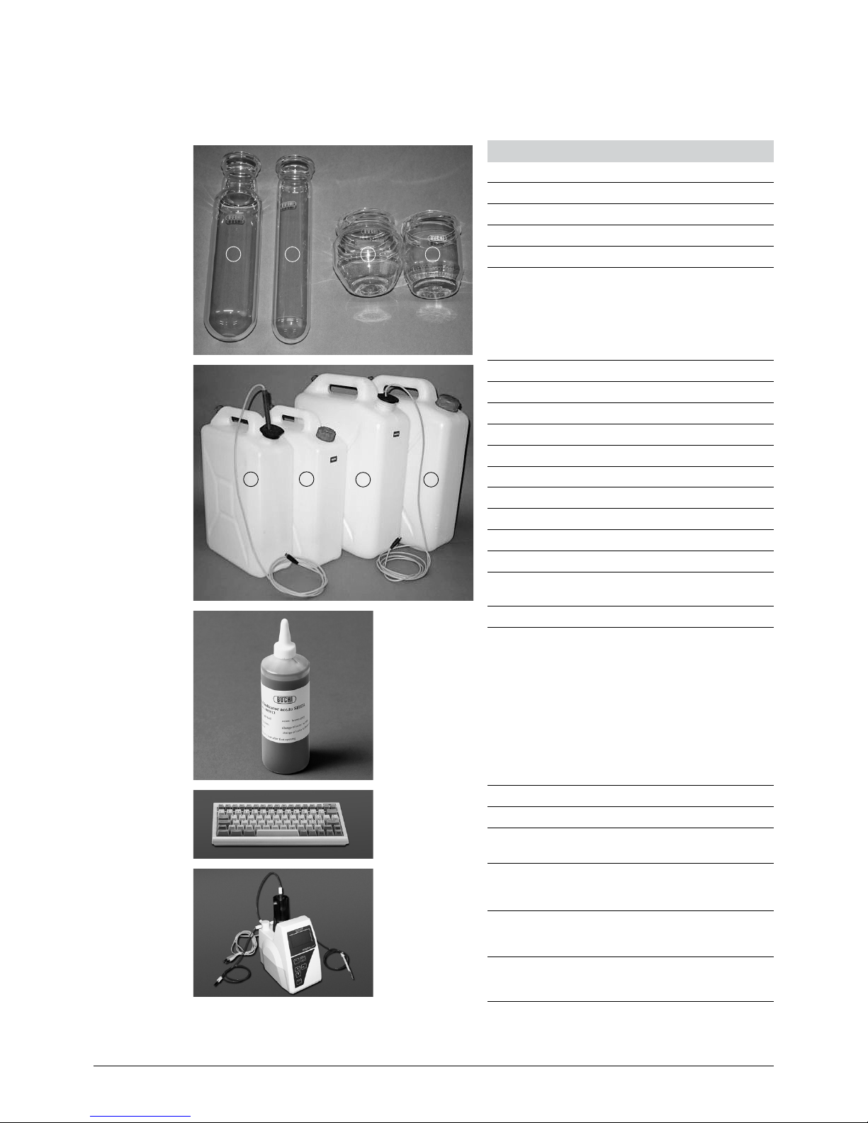
3.1.3 Optional accessories K-360
1
2
3
4
Table 3-3: Optional accessories K-360
Product Order number
a Sample tube (set of 4), 500 mL 43982
b Set of sample tubes (set of 4), 300 mL 37377
c Receiving vessel 420 mL 43390
d Receiving vessel 340 mL 43333
7
6 8
5
Tanks without level sensors, including caps
e 10 L chemicals 43468
e 10 L waste 43470
h 20 L chemicals 43469
h 20 L waste 43471
Tanks with level sensors, including caps
g 10 L chemicals 43472
g 10 L waste 43374
f 20 L chemicals 43473
f 20 L waste 43475
Indicator according to Sher, 100 mL 03512
External PC keyboard (US) 31456
External PC keyboard (D) 31457
External dosage device for back titration,
115 V
43367
External dosage device for back titration,
230 V
43596
Cable for external dosage device for back
titration (Schott Titronic)
43621
Page 15

3 Technical data
15
KjelFlex K-360 Operation Manual, Version D
Table 3-3: Optional accessories K-360
Product Order number
Sample tube holder for 4 sample tubes,
500 mL each
16951
Holder for 6 sample tubes, 300 mL 43039
Holder for 12 sample tubes, 300 mL 43041
Titration set 43698
Splash protector for Devarda method 43335
Connection cable to:
Mettler (DL15 / 22) titrator
43616
Metrohm (785 / 719 / 702)
Mettler (Txx) titrator
43617
Metrohm (848) titrator 11055333
Schott titrator 43618
Radiometer titrator 43619
Adapter for Metrohm 719 / 702 47803
Page 16

3 Technical data
16
KjelFlex K-360 Operation Manual, Version D
Table 3-3: Optional accessories K-360 (cont.)
Product Order number
SO2 accessory 48680
IQ/OQ set for K–360, English 93189
IQ/OQ set for K–360, German 45541
Repeating OQ, English 11055493
Repeating OQ, German 11055494
3.2 Technical data K-360
Table 3-4: Technical data K-360
KjelFlex K-360
Power consumption max. 2.2 kW
Connection voltage 220 - 240 VAC ± 10%
Frequency 50/60 Hz
Mains connection 3-pole (P, N, E) via power cord
Recovery rate ≥ 99.5%
Reproducibility (RSD) ≤ ± 1%
Detection limit ≥ 0.1 mg Nitrogen
Vapor output control 30 - 100%
Environmental conditions
Temperature
Altitude
Humidity
for indoor use only
5 - 35 °C
up to 2000 m
maximum relative humidity 80% for temperatures up to
31 °C decreasing linearly to 67% relative humidity at
35 °C
Installation category II
Pollution degree 2
Dimensions (W x H x D) 405 x 660 x 400 mm
Weight 22 kg
Printer interface USB 2.0, PCL 6
Page 17

3 Technical data
17
KjelFlex K-360 Operation Manual, Version D
3.3 Titration solution
The amount of sample and the concentration of the titrant should be optimized, so that the titrant
volume is between 2 and 18 mL (burette volume: 20 mL).
Table 3-5: Titration solution 1
N-amount N-content Sample size Titrant Titrant concentration Titrant volume
5 mg N 0.5 % N 1 g
H2SO
4
0.01 mol/L
17.8 mL
10 mg N 1.0 % N 1 g
H2SO
4
0.05 mol/L
7.1 mL
50 mg N 5 % N 0.1 g
H2SO
4
0.01 mol/L
17.8 mL
100 mg N 10 % N 1 g
H2SO
4
0.25 mol/L
14.3 mL
100 mg N 10 % N 1 g
H2SO
4
0.5 mol/L
7.1 mL
200 mg N 20 % N 1 g
H2SO
4
0.5 mol/L
14.3 mL
200 mg N 20 % N 1 g
H2SO
4
1 mol/L
7.1 mL
Table 3-6: Titration solution 2
P-content P-factor N-content Sample size Titrant Titrant concentration Titrant volume
1 % P 6.25 0.16 % N 2 g
H2SO
4
0.01 mol/L
11.42 mL
2 % P 6.25 0.32 % N 1 g
H2SO
4
0.01 mol/L
11.42 mL
5 % P 6.25 0.80 % N 2 g
H2SO
4
0.1 mol/L
5.71 mL
10 % P 6.25 1.6 % N 2 g
H2SO
4
0.1 mol/L
11.42 mL
10 % P 6.25 1.6 % N 2 g
H2SO
4
0.25 mol/L
4.57 mL
20 % P 6.25 3.2 % N 2 g
H2SO
4
0.25 mol/L
9.14 mL
50 % P 6.25 8.0 % N 2 g
H2SO
4
0.5 mol/L
11.42 mL
General recommendation
Hydrochloric acid has the disadvantage of degassing. Therefore BUCHI recommends to use sulfuric
acid as titrant.
The correction factor for self prepared solutions is called a titer.
The use of standardized titration solutions make a titer determination unnecessary.
Exact titrant concentration = concentration x titer
The titer of the titrant must be known. In case, it is unknown, it must be determined.
Example: Exact titrant concentration = 0.100 mol/L x 0.998
3.4 Reference substances
Table 3-7: Reference substances
Name Purity % N theoretical
(100 % purity)
Recommended
sample size
Recommended titrant
concentration
Digestion necessary
Ammonium
dihydrogen
phosphate
99.5 12.18 0.8 g c(H2SO4) = 0.25
mol/L
No
Glycine 99.7 18.66 0.5 g c(H2SO4) = 0.25
mol/L
Yes
Phenylalanine 99.0 8.47 0.9 g c(H2SO4) = 0.25
mol/L
Yes
Ammonium
sulfate
99.5 21.21 0.4 g c(H2SO4) = 0.25
mol/L
No
Page 18

3 Technical data
18
KjelFlex K-360 Operation Manual, Version D
3.5 Materials used
Table 3-8: Materials used for the K-360
Component Material designation Material code
Housing Polyurethane PUR / UL V0
Glass parts Borosilicate glass 3.3 DIN/ISO 3585
Steam generator isolation Ceramic fiber Multitherm 550
Steam generator housing Stainless steel 1.4301
Protective door Polymethyl methacrylate PMMA
Condenser cover Polymethyl methacrylate PMMA
Connecting stopper Hypalon CSM
Plastic splash protector Glass fiber reinforced polypropylene PP
Stop-cock Polypropylene/polyethylene PP/PE
Page 19

4 Description of function
19
KjelFlex K-360 Operation Manual, Version D
4 Description of function
This chapter explains the basic principle of the instrument, shows how it is structured and gives a
functional description of the assemblies.
4.1 Instrument overview
1
2
3
4
5
6
a Splash protector
b Sample tube
c Protective door
d Condenser
e Operating panel
f Service door
Fig. 4.1: Instrument overview
Page 20

4 Description of function
20
KjelFlex K-360 Operation Manual, Version D
4.2 Function principle
The KjelFlex K-360 is suitable for determining nitrogen using the Kjeldahl (TKN; Total Kjeldahl Nitrogen)
and Devarda methods as well as for other distillations of steam-volatile substances (e.g. of alcohol,
SO2, volatile acids).
5
1
3
4
2
6
a Sample tube
b Splash protector
c Steam generator
d Condenser
e Distillate outlet tube
f Receiving vessel with receiver solution
Fig. 4.2: Function principle
Steam is introduced into the sample solution (in sample tube a) to drive out volatile components
(such as ammonia, alcohol, etc.). After condensation (in condenser d) the distillate is collected in a
receiver solution (in receiving vessel f).
4.3 Kjeldahl applications
Determination of nitrogen/protein.
For system configuration with reagent-pump:
Warnmeldung
4.4 Non-Kjeldahl applications
Typical examples for non-Kjeldahl methods.
Determination of:
• SO
2
• Phenol
• Formaldehyde
• TVBN
• Alcohol
• Volatile acids
Page 21

4 Description of function
21
KjelFlex K-360 Operation Manual, Version D
Fig. 4.3: Stop-cock
The stop-cock is located at the inside of the service door.
To carry out a Kjeldahl application the stop-cock must be in downwards position.
To carry out a non-Kjeldahl application the stop-cock must be in horizontal position.
!
CAUTION
Risk of burnings by hot machine parts and water steam.
• Let the system cool down before performing any service.
• Do not operate the instrument when enclosure is open or removed.
Notice
Wrong stop-cock setting will result in system overpressure. Tubing may come off.
• Set stop-cock to correct working-position.
Page 22

4 Description of function
22
KjelFlex K-360 Operation Manual, Version D
NOTE
A warning message will be displayed, when the method is changed from a Kjeldahl to a non-Kjeldahl
method or vice versa:
Fig. 4.4: Warning message on the display Fig. 4.5: Warning message on the display
4.5 Operational elements of the instrument
1
2
3
6
7
8
5
3 3
3
4
9
a Stop button to stop a process
b Display
c Functional buttons to operate the software
d Navigation buttons to navigate within the
software
e Start button to start a process like preheating,
priming, cleaning, etc.
f Enter button to move forward within the sub-
menu structure
g Escape button
h Delete button to delete a digit entered via the
keypad
i Keypad
Fig. 4.6: Controls of the instrument
Page 23

5 Putting into operation
23
KjelFlex K-360 Operation Manual, Version D
5 Putting into operation
This chapter describes how the instrument is installed and gives instructions on initial startup.
NOTE
Inspect the instrument for damages during unpacking. If necessary, prepare a status report immediately to inform the postal company, railway company or transportation company.
Keep the original packaging for future transportation.
5.1 Installation site
Install the instrument on a clean, flat and stable base and place the tanks for chemicals beside the
instrument (not higher and not more than 1 m lower).
Notice
Reduced instrument safety and lifetime due to improper handling and installation location.
• Do not place any object on top of the instrument.
• Keep a free safety space of 30 cm around the instrument.
• Do not place items behind the instrument.
• Do not operate the instrument within an fume cabinet.
5.2 Electrical connections
L
N
IEC-60320, Type: C13
Fig. 5.1: Electrical connections
!
WARNING
Death or serious burnings by electric shock.
• Mains voltage must match the voltage reading on the type plate.
• Instrument must be earthed by the mains socket.
• Only use a molded 3-pole device plug (IEC-60320, type C13 or C15).
• Do not use damaged cables.
Page 24

5 Putting into operation
24
KjelFlex K-360 Operation Manual, Version D
5.3 Reagent and water connections
1
2
3
6
7
5
4
a H3BO3 inlet from tank
b H2O inlet from tank
c NaOH inlet from tank
d Reagent inlet for acid resistant pump
e Cooling water inlet
f Cooling water outlet
g Drain to waste
Fig. 5.2: Reagent and water connections
All pumps are self-priming, no overpressure is necessary at the tanks.
5.3.1 Cooling water connection
The water pressure should be at a maximum of 4 bar. The built in valve reduces the water flow to 1.2
liters per minute.
The flanged screw coupling for the water connection has a standard screw thread of G ¾”.
5.3.2 Drainage of cooling water
Place the drain hose for the cooling water directly into the drain. For this purpose, shorten the silicone
hose to the optimal length. The drain hose should not show any kinks, sharp bends and/or siphoning
effect. Prevent flooding inside and outside the instrument by securing the drain hose.
Page 25

5 Putting into operation
25
KjelFlex K-360 Operation Manual, Version D
5.3.3 Waste/aspiration hoses
The distillation and sample residue can be aspirated and collected separately from the cooling water.
For this purpose a separate collection tank is necessary. The collection tank must be located lower
than the instrument to guarantee proper drainage.
Connect the waste/aspiration hose to the waste outlet and place it directly into the drain (sink). For this
purpose, shorten the EPDM hose to the optimal length. In order to prevent any back-flow, the hose
may be placed maximum 10 cm into the tank.
5.3.4 Storage tank connection
To connect the storage tanks, proceed as follows:
• Cut the Nylflex hose into pieces of the appropriate length (use a Viton hose for the acid resistant
pump).
• Insert a FEP suction hose into the Nylflex hose.
• Push an EPDM sealing ring over the Nylflex hose.
• Now fasten the hoses to the tank with the red screw cover.
• Connect the hoses at the appropriate connections at the instrument side and secure them with the
clamps.
Fig. 5.3: Tank connection
Notice
Possible instrument damage by calcification or corrosion.
• Use only distilled water in the H2O storage tank to operate the system.
• Do not mix up liquids at the instrument inlets, observe the inlet labelling.
Page 26

5 Putting into operation
26
KjelFlex K-360 Operation Manual, Version D
5.4 Level sensors (optional)
Level sensors are optionally available for all Buchi tanks. The individual sensors are connected to the
corresponding socket.
H2O: Connection to the tank with distilled water for the steam generator and sample tube.
NaOH: Connection to the tank with sodium hydroxide.
H3BO3: Connection to the tank with boric acid.
Waste: Connection to the waste tank.
The length of the level sensor for chemicals can be adapted by means of the the rubber cap, see Fig.
5.4.
NOTE
The level sensor for the waste tank must be set active at: Configuration, Settings, Level Sensor
Waste. This is not necessary for the other sensors.
Fig. 5.4: Adapting the length of the level sensor
Adapt the length of the level sensor for chemical by moving up and down the rubber cap according to
the size of the tank.
5.5 Connections to peripheral devices
5
7
1
3
4
8
2
6
9
The following instruments and accessories can
be connected to the K-360:
a Level sensors
b TTL interface to a titrator
c TTL interface to a dispenser (external
dosage device for back titration)
d USB interface to a printer
e USB interface (for service purposes)
f COM1 (reserve)
g RS interface to a dispenser
h RS interface to a titrator
i External keyboard
Fig. 5.5: Connections to peripheral devices
Page 27

5 Putting into operation
27
KjelFlex K-360 Operation Manual, Version D
5.5.1 Connecting a printer
The K-360 supports printers with USB port and language PCL 3 or higher (e.g. PCL 5, PCL 5e, PCL
6, PCL 7 etc.) which are available e.g. from Hewlett Packard or Lexmark.
The printer is connected to the USB port.
To print out the results directly after each determination, go to Configuration > Titrator and set Print
Data to Yes. You also have to configure the titrator for data printout. For this purpose, please consult
the corresponding manual.
The following printers have been tested together with the K-360:
• HP Color LaserJet 3700DN
• HP Deskjet 1280c
• Brother mfc 8820d
• Lexmark E120
• Lexmark E240
• HP OfficeJet Pro K550
• Brother HL-5240
• OKI B4250
The following printer causes problems:
• HP LaserJet 1022
5.5.2 External keyboard
As an option, an external keyboard can be connected to the instrument to make data entry more
comfortable. The internal keyboard is still active, even if an external keyboard is connected.
Special functions on the external keyboard are:
Table 5-1: External keyboard
K-360 keyboard External keyboard
START F3
STOP F2
Function key below display F5...F8
Other functions (e. g. up/down) are the same as on the internal keyboard.
Page 28

5 Putting into operation
28
KjelFlex K-360 Operation Manual, Version D
5.6 Boric acid titration and back titration
The K-360 offers the possibility to work with boric
acid titration or back titration. It is recommended
to choose a permanent configuration as different
hardware is needed to convert between the two
titration methods.
Buchi recommends to work with boric acid titration.
Boric acid titration
Receiving vessel: Boric acid solution 2 % or 4 %,
adjusted to pH 4.65.
Titrant: Standardized sulfuric acid solution or hydrochloric acid solution
It is recommended to use boric acid solution 4 %,
adjusted to pH 4.65 and standardized sulfuric acid
solution.
The K-360 includes all necessary hardware to
work with boric acid titration. Boric acid is dosed
via the integrated pump.
Fig. 5.6: K-360 for boric acid titration (with titrator)
Back titration
Receiving vessel: Standardized sulfuric acid
Titrant: Standardized sodium hydroxide solution
An external dosage device must be connected for
the exact addition of the receiving solution. See
chapter 6.4.6 for information on the installation
and set-up of the external dosage device.
Fig. 5.7: K-360 for back titration (with external dosage device)
Page 29

6 Operation
29
KjelFlex K-360 Operation Manual, Version D
6 Operation
This chapter gives examples of typical instrument applications and instructions on how to operate the
instrument properly and safely.
!
CAUTION
Risk of cuts by defective glassparts.
• Handle glassparts with care.
• Exchange defective glassparts directly.
• Do not operate the instrument when glassparts are damaged.
!
WARNING
Serious chemical burnings by corrosives.
• Observe supplementary data sheets of all used chemicals.
• Wear protective goggles.
• Wear protective gloves.
• Wear protective clothing.
NOTE
Close unused connections with plug caps.
Page 30

6 Operation
30
KjelFlex K-360 Operation Manual, Version D
6.1 Overview over the software structure
Main menu 2nd stage 3rd stage 4th stage
1 Determination Sample List
2 Preheating
3 Priming Priming Method
H2O, NaOH, H3BO3,
(Reagent) volumes
Reaction Time
Steam Power
Distillation Time
Titration Start
Titr. Type
Stirrer Speed
Aspiration Sample / Receiver
4 Cleaning Cleaning Method
H2O
Steam Power
Distillation Time
5 Aspiration Aspiration Method Aspirate Sample
Aspirate Receiver
6 Results Result List
7 Methods Method List
Page 31

6 Operation
31
KjelFlex K-360 Operation Manual, Version D
Main menu 2nd stage 3rd stage 4th stage
8 Configuration
1 Pump Calibration
Calibration of: H2O, NaOH,
H3BO3, (Reagent) Pump
2 Set Date and Time Date / Time Details
3 Settings
Language
Display Contrast
Demo Mode
Endless Mode
Level Sensor Waste
Rec. Vessel Present
Reagent Pump
4 Titrator
Print Data
Titrator Present
Titrator Signals
Dispenser Signals
Signal “ready”
5 Dispenser Signal “active”
Signal “end”
6 User / Password User / Password List
7 Keypad Keypad Time
Page 32

6 Operation
32
KjelFlex K-360 Operation Manual, Version D
Main menu 2nd stage 3rd stage 4th stage
9 Diagnostics
1 Operational Tests
Valves
Pumps
Stirrer
Alarm
Steam Unit
Titrator
Dispenser
Battery
2 Test Sensor
Cooling Water Flow
Tube Shield Switch
Tube Present Check Switch
Service Door Switch
Steam Unit
Level Sensors
Titrator
Dispenser
Voltage
Temperature
3 Test Printer
Print Page
Formfeed
Reset
4 Operating Hours
Steam Generator
Number of Distillations
5 Hardware Info
Production Date
Serial Number
CPU
PCB
6 Service Test
Page 33

6 Operation
33
KjelFlex K-360 Operation Manual, Version D
6.2 General information on buttons
The following control buttons are available in the software for navigation and input confirmation:
Go to the main menu
Confirm a message and get back to the previous screen
Save
Close a screen (without saving) and get back to the previous one
Delete
Edit
Mark the currently highlighted result/method in the list as first result/method on a report
Mark the currently highlighted result/method in the list as last result/method on a report
Add 10 mL of H2O
Add 10 mL of H3BO
3
Add 10 mL of NaOH
Add 10 mL of reagent
Go to the method screen to view, define or edit a method
Go to the Method List screen
Print
Switch from Standby to Ready mode
Go to the sample screen to define a sample
Switch from Ready to Standby mode
Go to the status screen to view the status, the time and the user logged in
Reset the operating hours / numbers of distillation
Switch to the screen with Operational Tests
Switch to the screen with Test Sensors
Switch to offline operation in the Operational Tests screen
Switch to online operation in the Operational Tests screen
Run the pump in the Pump Calibration screen
Calibrate the pump in the Pump Calibration screen
Page 34

6 Operation
34
KjelFlex K-360 Operation Manual, Version D
Change password
Define a new user
Switch to previous screen e.g. in Service Test
Switch to next screen e.g. in Service Test
Confirm a message or affirm a question
Negate a question
Backward button to move to the previous digit
Forward button to move to the next digit
Move up within the entries of a screen
Move down within the entries of a screen
6.3 Overview on how to prepare the instrument for routine operation
Configure the software according to the following steps to prepare it for routine operation:
1. Standard instrument configuration
2. Distillation methods
3. System preparation
4. Individual working methods
6.3.1 Standard instrument configuration
This configuration consists of typical settings, which have to be defined before the instrument is used
for the first time. As long as the instrument is not updated or extended by any additional optional
accessory these settings do not have to be changed again.
The settings are carried out in the menu Configuration.
6.3.2 Distillation methods
The distillation methods you like to use can be defined in the menu Method. For this purpose you use
an existing Buchi standard method and modify it to your needs. Thus you can define up to 50 individual methods according to e.g. distillation time, aspiration yes/no, volume of boric acid/NaOH/water,
etc.
6.3.3 System preparation
The system preparation is carried out every day before the instrument is taken into operation and an
analysis is started. It consists of e.g. filling the hoses and priming the system.
Page 35

6 Operation
35
KjelFlex K-360 Operation Manual, Version D
6.3.4 Individual working method
The software offers two working methods for sample determination, the single sample analysis and
the rack oriented analysis.
Single sample analysis
This working method is straight forward and is used especially when you are not interested in sample
name input and storing the volume consumption of the titrant solution in the system memory, see also
chapter 6.8.1.
Rack oriented analysis
Here all sample names and the corresponding weight is entered prior to determination. The volume
consumption of the titrant solution is stored together with the sample name, see also chapter 6.8.2.
You can switch between these two working methods at any time.
6.4 Configuring the instrument
To configure the instrument in the Main Menu go to Configuration and press Enter. The following
screen appears:
Fig. 6.2: Configuration
NOTE
To access the individual menus you can either use the arrow keys to move up and down in the list
and press Enter or the Forward button or you can type in the number of the corresponding menu
directly (e.g. 3 for Settings).
Page 36

6 Operation
36
KjelFlex K-360 Operation Manual, Version D
6.4.1 Pump calibration
Go to Pump Calibration and press Enter. The following screen appears:
Fig. 6.3: Pump calibration
It is recommended to calibrate the pumps with the same volume as used for the methods. To perform
the calibration a graduated cylinder is needed.
To carry out the pump calibration, proceed as follows:
• Choose the required pump by pressing left / right arrow repeatedly, when e.g. “H20” is highlighted.
• Enter the quantity to be dosed (Dose Volume), e.g. 50 mL.
• Press Run to start dosing.
• Measure the dosed volume and enter the measured volume.
• Press Cal to calibrate the pump. When the calibration is finished a corresponding calibration factor
appears.
NOTE
Repeat this procedure until the entered and the dosed volume correspond. An acceptable difference
at 50 mL is ±2 mL. NaOH/H2O/Reagent can be dosed into the sample tube and then poured into a
graduated cylinder. H3BO3 is dosed directly into the receiving vessel and then poured into a graduated cylinder.
It is recommended to repeat the pump calibration regularly (once a month or every 100 distillations).
6.4.2 Setting date and time
Go to Set Date and Time and press Enter. The following screen appears:
Fig. 6.4: Date/Time
Enter the corresponding settings via keypad and press Save to store them.
Page 37

6 Operation
37
KjelFlex K-360 Operation Manual, Version D
NOTE
The day, month and year settings can be entered with one or two digits.
6.4.3 Defining general instrument settings
Go to Settings and press Enter. The following screen appears:
Fig. 6.5: Settings
The following settings can be entered:
• Language
• Display Contrast
• Demo Mode
• Endless Mode
• Level Sensor Waste
• Receiving Vessel present
• Reagent pump present
Enter the desired settings via arrow buttons and press Save to store them. These settings have to be
defined before the instrument is used for the first time.
6.4.4 Defining the titrator settings
Go to Titrator and press Enter. The following screen appears:
Fig. 6.6: Titrator
Press Edit to edit the settings. By changing the number at “Titrator present” the settings for the titrators listed in the following table will be adjusted automatically.
Page 38

6 Operation
38
KjelFlex K-360 Operation Manual, Version D
Table 6-1: Titrator settings
Titrator present Configuration Signal ready Signal active Signal end Baud Data bit Parity Stop bit
1 e.g. Mettler Toledo DL 15/22 Low No RS232 9600 8 no 2
2 e.g. Mettler Toledo T50/Txx No No RS232 4800 8 even 1
3 e.g. Metrohm Food Titrino
DMP785 / 719 / 702
No No RS232 9600 8 no 1
4 e.g. Schott TitroLine Easy No RS232 RS232 4800 7 no 1
5 e.g. Radiometer TitraLab 840 Low High Low 9600 8 no 1
6 e.g. Metrohm 848 Plus Low High RS232 19200 8 no 1
Custom other titrators
When you have selected “Custom” you can enter the corresponding settings via the arrow buttons
and press Save to store them.
At the moment there are the following titrator types that enable a signal transfer and thus an automatic
result display in the K-360 software:
• Mettler Toledo DL 15 / 22 / Txx
• Schott TitroLine Easy
• Metrohm Titrino DMP 785 / 719 / 702 / 848 Plus
To assure a correct signal transfer, the respective titrator has to be configurated according to the
Büchi specifications.
6.4.5 Boric acid / end point titration
Receiving vessel: see chapter 5.6
Titrant: see chapter 5.6
It is recommended to use boric acid solution 4%, adjusted to pH 4.65 and standardized sulfuric acid
solution.
Titrate the distillate with sulfuric acid standard solution to the end point of pH 4.65.
Defining settings to work with a titrator
Configuration > Settings > Rec Vessel present: Yes
Configuration > Titrator: Titrator present: (1, 2, 3, 4, 5, 6, Custom)
Methods > Select the corresponding method from the method list and press Enter
> Aspiration Sample: Yes
> Aspiration Rec. Sol’n: Yes
Defining settings without a titrator
Configuration > Settings > Rec Vessel Present: No
Configuration > Titrator: Titrator present: No
Methods > Select the corresponding method from the method list and press Enter
> Aspiration Sample: Yes
Page 39

6 Operation
39
KjelFlex K-360 Operation Manual, Version D
6.4.6 Back titration with dispenser
External dosage device for back titration
The external dosage device is connected to the port for the manual key button. The volume of the
receiving solution must be entered at the external dosage device. For this purpose, refer to the Operation Manual of the dosage device.
The K-360 sends an impulse to the connected device to start the dosing procedure.
Receiving vessel: Standardized sulfuric acid
Titrant: Standardized sodium hydroxide solution
Defining the K-360 settings for back titration
The following setting at the K-360 is a prerequisite for working with a dispenser:
Method > Titr. Type > Back Titration
Go to Configuration > Dispenser and press Enter. The following screen appears:
Fig. 6.7: Dispenser
Enter the corresponding settings via the arrow buttons and press Save to store them.
Table 6-2: Dispenser settings
Configuration Signal ready Signal active Signal end
Schott Titronic universal No No 60 s
6.4.7 Defining user and password settings
Go to User/Password and press Enter. The following screen appears:
Fig. 6.8: User/Password
Page 40

6 Operation
40
KjelFlex K-360 Operation Manual, Version D
To define a new user, press New. The following screen opens:
Fig. 6.9: User
Enter a new name and a password. To change your password, enter a new one and confirm it. Press
Save to store your settings.
NOTE
A password is not mandatory.
• When a password is used the corresponding user is indicated on the result printout list.
• When a password is forgotten, the determination can be started with the Buchi default login:
User name: buchi, password: buchi01.
When the Buchi default login is used, all other passwords will be deleted.
6.4.8 Defining the keypad settings
Go to Configuration > Keypad and press Enter. The following screen appears:
Fig. 6.10: Keypad
Set the desired Edit Time, i.e. the waiting time until a new character can be typed in, and press Save
to store your setting.
Page 41

6 Operation
41
KjelFlex K-360 Operation Manual, Version D
6.5 Defining a distillation method
The Standard method that is stored in the instrument cannot be deleted. It can be used as basis to
define further methods. Up to 50 different methods can be saved.
To define a method in the main menu go to Methods and press Enter. The Standard Method is
displayed in the Method List by default. Press Enter again, the following screen appears:
Fig. 6.11: Method
A method consists of the following settings:
• Name
• User
• Amount of chemicals to be dosed (H2O / NaOH / H3BO3 / Reagent)
• Reaction time
• Titration type
• Stirrer speed (Distillation / Titration)
• aspiration (Sample / Receiving vessel)
To define a new method, press Edit and enter the corresponding settings. Then press Save to store
them.
NOTE
For Kjeldahl applications define a volume of H2O and NaOH, for non-Kjeldahl applications, define the
volume of your used reagent (acid).
A list of all defined methods is displayed on pressing the List button:
Fig. 6.12: Method list
To print out a method, highlight the method-name in the list and press Print.
Page 42

6 Operation
42
KjelFlex K-360 Operation Manual, Version D
6.6 Instrument modes
The instrument has two different modes, Standby and Ready. In Ready mode the steam generator
heats continuously, so that a distillation can be started immediately. When the instrument is not operated for thirty minutes, it switches to Standby mode and stops heating to save electric power. When
it is switched back to Ready mode, it has to heat up first. You can see the icon “Process in progress”
(see position 3 in Fig. 6.8.3) flashing during heating.
Fig. 6.13: Standby mode
To switch from Standby to Ready mode, press Menu and subsequently Ready.
6.7 System preparation
6.7.1 Preheating
The glass parts of the distillation system have to be preheated prior to analysis. Use a clean and
empty sample tube for this processing. It is recommended to perform a preheating, when the glass
(splash protector) has cooled down. The preheating time is predefined.
6.7.2 Priming
This preparation procedure includes distillation and titration with a clean and empty sample tube. It is
recommended to perform a priming at least once a day, before starting analysis. The priming method
can be modified.
6.7.3 Cleaning
At the end of a day, the system should be rinsed thoroughly by carrying out a cleaning. The splash
protector and the condenser are rinsed with water to remove sodium hydroxide residues. With regular
cleaning, the lifetime of the glass parts can be extended. The cleaning method is predefined, but can
be modified and adapted to the size of the sample tube.
6.7.4 Aspiration
With this procedure sample residue in the sample tube and titration residue in the receiving vessel can be
aspirated.
Page 43

6 Operation
43
KjelFlex K-360 Operation Manual, Version D
6.8 Carrying out a distillation
To carry out a distillation, proceed as follows:
• Switch on the instrument and wait until the steam generator is ready.
• Insert the sample tube containing the sample.
• If you do not work with the titration set, prepare a conical flask or a similar receptacle with a volume
of about 250 mL as receiving vessel.
For sample analyses there are two different approaches, depending on how you prefer to work:
• Single sample analyses
• Rack oriented analyses
6.8.1 Single sample analysis
For single sample analyses, no predefined sample list is needed for identification. To start an analysis,
provide a sample and press the Sample button in the main menu. The following screen opens:
Fig. 6.14: Sample
Enter a sample name and sample weight via keypad. Choose the desired method and press Start to
start the distillation process.
NOTE
• When you re-enter the screen, sample name, weight, unit, type and method are set to the latest
entered settings.
• You can start a determination at any time without a sample name or weight input.
Page 44

6 Operation
44
KjelFlex K-360 Operation Manual, Version D
6.8.2 Rack oriented analysis
For the rack oriented analyses all sample data (name, weight, etc.) have to be entered.
The Sample List screen opens:
Fig. 6.15: Sample List
This screen allows to define a Sample List entry for every sample provided. To define a new entry,
press Edit. The Sample screen opens. Enter sample name and weight and press Save. The newly
created entry now appears in the list. Repeat this step for all provided samples.
To start distillation of a sample, enter Determination in the main menu, select an entry and press the
Start button. The distillation starts.
6.8.3 Analysis screen
5
7
1
3
4
2
6
a Status designation
b Titrator icon (titrator connected)
c Icon (turning when process is in progress,
flashing when instrument is heating, standing
still when instrument is ready)
d Current process step
e Name of currently processed sample
f Current date and time
g User currently logged in
Fig. 6.16: Analysis screen
Page 45

6 Operation
45
KjelFlex K-360 Operation Manual, Version D
6.8.4 Result screen
If a titrator has been connected to the K-360, which does not provide direct data transfer, the result
screen opens after a distillation. The corresponding mL-value indicated on the connected titrator can
be manually added under Result via keypad. Press OK to save the entry.
Fig. 6.17: Result screen
In case the connected titrator provides direct data transfer, the result is stored automatically.
If no titrator is connected, no Result screen is displayed.
6.8.5 Result list
To view the list of results measured, go to Results in the main menu and press Enter or just press 6.
The Result List opens:
Fig. 6.18: Result list
The result list can hold a maximum of 500 results. If this number is beeing exceeded, the “oldest”
results in the list will be overwritten successively by new results.
To print out a selection of results, highlight the first result and press the First button. Then highlight the
last result that should appear in the list and press the Last button to define your selection. Now press
Print.
For a detailed printout of a result, highlight a single result in the list and press Print.
Page 46

6 Operation
46
KjelFlex K-360 Operation Manual, Version D
6.8.6 After distillation
If you do not work with the titration set, empty the receiving vessel. The content of the receiving vessel
of the titration set is automatically aspirated at the end of the distillation, if this is configured within the
method.
It is recommended to clean the system using the cleaning method at the end of the day.
NOTE
The water volume can be adapted in the menu Cleaning under H2O.
6.9 Switching ON/OFF checklist
To switch on and preheat the instrument, proceed as follows:
• Check the filling level of the supply tanks.
• Open the main water tap.
• Switch on the instrument and wait until the steam generator is ready.
• Insert an empty sample tube and an empty receiving vessel.
• Close the protective door.
• Start the preheating/priming by pressing the Start button in the corresponding menu.
• Start the distillation by pressing the Start button.
To switch off the instrument, proceed as follows:
• Start the cleaning process (see chapter 7.12).
• Rinse the acid resistant pump with distilled water (in case it was used for the dosage of strong
acids, e.g. HCl).
• Switch off the instrument.
• Close the main water tap.
Page 47

7 Maintenance
47
KjelFlex K-360 Operation Manual, Version D
7 Maintenance
This chapter gives instructions on all maintenance work to be performed in order to keep the instrument in good working condition. All working steps described herein shall only be carried out by trained
personnel. After the maintenance has been finished, the person in charge with this maintenance must
bring the system into standard operating condition (e.g. close the service door) and check the proper
function of the instrument.
!
WARNING
Death or serious injuries by electric shock.
• Switch off the instrument and remove the power cord.
• Do not bring any electrical component into contact with fluids.
• Do not operate the instrument when enclosure is open or removed.
!
CAUTION
Risk of burnings by hot machine parts and water steam.
• Let the system cool down for 30 minutes before performing any service.
• Do not operate the instrument when enclosure is open or removed.
!
WARNING
Death or serious burnings by flammable vapors.
• Remove all sources of flammable vapor.
• Avoid spark formation.
• Do not operate with open flames.
!
WARNING
Serious chemical burnings by corrosives.
• Observe supplementary data sheets of all used chemicals.
• Wear protective goggles.
• Wear protective gloves.
• Wear protective clothing.
Note
The service door may only be opened for maintenance or service purposes and to switch the stopcock
Page 48

7 Maintenance
48
KjelFlex K-360 Operation Manual, Version D
7.1 Daily maintenance
Regular cleaning is vital to ensure proper instrument functioning. Thus the deposits of caustic
substances within the instrument (e.g. causing degradation of glassware) can be avoided.
7.1.1 Cleaning the housing
Check the housing for defects (switches, plugs) and clean it with a damp cloth.
NOTICE
Risk of housing damage by solvents and acids.
• Do not clean the housing with solvents.
• Wipe off any acid drops immediately.
Open the service door and perform a visual check of all parts inside. Make sure that there is no leaking
at hoses and valves.
7.1.2 Cleaning the glass parts
To extend the lifetime of the glass parts, we recommend to perform a cleaning at the end of the day.
For this purpose in the main menu select “Cleaning” and press the Start button. The system will start a
distillation with 300 mL water for a period of 5 minutes.
Page 49

7 Maintenance
49
KjelFlex K-360 Operation Manual, Version D
7.1.3 Cleaning the rubber bung seal
Clean the seal with a damp cloth.
7.2 Monthly maintenance
7.2.1 Calibrating the pumps
We recommend to calibrate the pumps once a month or every 100 distillations. Before calibrating the
pumps, make sure that the hoses are not bent inside the instrument. For a description on how to carry
out the calibration, see chapter 6.4.1.
7.2.2 Checking the distillate amount
To check the distillate amount, wait until the steam generator is ready, i.e. the preheating has been
performed. Then run a single sample with an empty tube and an empty receiving vessel with the
following parameters:
Table 7-1: Checking the distillate amount
Parameter Setting
Check distillate amount: Distillation
Sample tube: empty
Water: 0 mL
NaOH: 0 mL
Distillation time: 5:00
Measure the distillate amount by means of a measuring flask. With the above parameters it should be
minimum 130 mL.
7.3 Maintenance as required
We recommend to replace the parts listed in this chapter depending on the instrument use or at least
once a year.
7.3.1 Cleaning the splash protector
Glass splash protector:
It is recommended to unmount the splash protector if residues are visible in its upper part. It can be
cleaned with commercially cleaning agent or in an ultrasonic bath.
Plastic splash protector:
It is recommended to unmount the splash protector if you see the blank values continually increasing.
It can be cleaned with commercially cleaning agent or in an ultrasonic bath.
When unmounting the splash protector for cleaning, clean the seal as well to prolong its lifetime.
Rinse it with water, dry it with a soft cloth, remount it and put the splash protector back in place.
Page 50

7 Maintenance
50
KjelFlex K-360 Operation Manual, Version D
NOTICE
Risk of sealing damage by sharp edges or lubricants.
• When installing, move sealing in perpendicular axis to the glass parts.
• Do not touch sealing with potentially sharp objects.
• Do not apply grease or any other lubricant to the sealing.
For further information on how to unmount and remount the splash protector, see chapter 7.3.3.
7.3.2 Replacing the splash protector
Replace the Splash protector after approximately 5000 determinations.
7.3.3 Replacing the rubber bung seals and the splash protector
We recommend to replace the parts listed below depending on the instrument use, at least once a
year.
The seals are subject to wear and tear, thus you should check them regularly. We recommend to
replace them once a year. The following parts need to be replaced (see also the spare parts list):
1
2
3
a Accessories splash protector
b Gasket for splash protector, complete
c SVL 22 sealing
Make sure that the instrument is cooled down.
Open the service door and loosen the two tubings
shown on the picture.
Page 51

7 Maintenance
51
KjelFlex K-360 Operation Manual, Version D
Open the screw-type cap of the hose.
Now loosen the two screws with black head to
remove the metal holder at the front side.
Carefully remove the bracket.
Now unscrew the black plastic screw with a
polygrip. Make sure to do this gently as you might
break the glass parts. This part of the procedure is
the most critical one.
Carefully remove the splash protector.
Unscrew the gasket.
Page 52

7 Maintenance
52
KjelFlex K-360 Operation Manual, Version D
Pull out the steam tubing.
To replace the rubber parts pull off the connecting
screw. The smaller sealing is located inside.
Fig. 7.1: Installing the glass assembly
Exchange all the rubber and plastic parts shown on the first picture of chapter 7.3.3.
Put back the replaced parts in the reverse order and make sure to tighten the screw on top of the
splash protector very carefully with the Polygrip.
7.3.4 Glass parts
Replace the sample tubes and the condenser if broken.
7.3.5 Replacing the hoses
Depending on the applications and the used chemicals, it might be necessary to replace some of the
hoses inside of the instrument to avoid leakages or aspiration problems.
Page 53

7 Maintenance
53
KjelFlex K-360 Operation Manual, Version D
7.4 Yearly maintenance
7.4.1 Customer service
In order to avoid down times of a KjelFlex, we recommend to have the following parts replaced at least
once a year by an authorized service person:
• Membranes of the aspiration module valves
• NaOH pump, the other pumps if required
Only authorised service personnel are allowed to perform repair work on the instrument. These
persons have a comprehensive technical training and knowledge of possible dangers which might
arise from the instrument.
Addresses of official Buchi customer service offices are given on the Buchi website under:
www.buchi.com. If malfunctions occur on your instrument or you have technical questions or application problems, contact one of these offices.
The customer service offers the following:
• Spare part delivery
• Repairs
• Technical advice
7.4.2 Decalcification of the steam generator
To decalcify the steam generator proceed as follows:
1. Make sure that the steam generator is cooled down (switch off the unit and let it cool down for at
least 30 minutes)
2. Remove the water of the steam generator (see 9.1 Emptying the steam generator)
3. Mix about 0.8 L of solution for decalcification (use e.g. approx. 160 g citric acid or approx. 80 g
amidosulfonic acid dissolved in 0.8 L water)
4. Remove the hose from the H2O-inlet on the back of the instrument.
5. Connect a new hose to the H2O-inlet and put its free end into decalcification solution
6. Switch on the K-360
7. After initialization the pump starts running
8. Switch off the unit after the steam generator is filled up with the solution (pump stops running)
9. Let the solution dissolve the lime for 0.5 – 1 hour
10. Remove the solution of the steam generator (see step 1 and 2)
11. Perform a second decalcification (see step 6 – 10)
12. Connect the hose from the water tank with the inlet of H2O
13. Flush the steam generator 2 – 3 times with distilled water (see step 6 – 8 and 10)
14. Perform 2 – 3 times a CLEANING (cleaning method) of the instrument
Page 54

8 Troubleshooting
54
KjelFlex K-360 Operation Manual, Version D
8 Troubleshooting
This chapter helps to resume operation after a minor problem has occurred with the instrument. It lists
possible occurrences, their probable cause and suggests how to remedy the problem.
The troubleshooting table below lists possible malfunctions and errors of the instrument. The operator
is enabled to correct some of those problems or errors by him/herself. For this, appropriate corrective
measures are listed in the column “Corrective measure”.
The elimination of more complicated malfunctions or errors is usually performed by a Buchi technical
engineer who has access to the official service manuals. In this case, please refer to your local Buchi
customer service agent.
8.1 Malfunctions and their remedy
Table 8-1: General malfunctions and their remedy
Error number / Error indication Possible cause Corrective measure
0 The current process was stopped. Press OK, aspirate manually and start
again
1 Steam Valve (Y1 on) malfunction. Contact the Buchi customer service
2 Aspiration Out Valve (Y2 on) malfunction. Contact the Buchi customer service
3 Aspiration In Valve (Y3 on) malfunction. Contact the Buchi customer service
4 Receiver Valve (Y4 on) malfunction. Contact the Buchi customer service
5 Cooling Water Valve (Y5 on) malfunction. Contact the Buchi customer service
8 Injection Valve (Y8 on) malfunction. Contact the Buchi customer service
9 Water Valve (Y9 on) malfunction. Contact the Buchi customer service
11 Steam Valve (Y1 off) malfunction. Contact the Buchi customer service
12 Aspiration Out Valve (Y2 off) malfunction. Contact the Buchi customer service
13 Aspiration In Valve (Y3 off) malfunction. Contact the Buchi customer service
14 Receiver Valve (Y4 off) malfunction. Contact the Buchi customer service
15 Cooling Water Valve (Y5 off) malfunction. Contact the Buchi customer service
18 Injection Valve (Y8 off) malfunction. Contact the Buchi customer service
19 Water Valve (Y9 off) malfunction. Contact the Buchi customer service
20 H2O Pump (M1 on) malfunction. Contact the Buchi customer service
21 NaOH Pump (M2 on) malfunction. Contact the Buchi customer service
22 Reagent Pump (M3 on) malfunction. Contact the Buchi customer service
23 H3BO3 Pump (M4 on) malfunction. Contact the Buchi customer service
25 H2O Pump (M1 off) malfunction. Contact the Buchi customer service
26 NaOH Pump (M2 off) malfunction. Contact the Buchi customer service
27 Reagent Pump (M3 off) malfunction. Contact the Buchi customer service
28 H3BO3 Pump (M4 off) malfunction. Contact the Buchi customer service
30 Calibration out of range, check pump. Check connection K-360/tank, check pump
33 The service door is open. If a process was
in progress, it may have been stopped.
Close the service door, start again
34 The splash protector door is open. If a
process was in progress, it may have been
stopped.
Close the splash protector door, start again
Page 55

8 Troubleshooting
55
KjelFlex K-360 Operation Manual, Version D
Table 8-1: General malfunctions and their remedy (cont.)
Error number / Error indication Possible cause Corrective measure
35 There is no sample tube. Sample tube present? Sample tube defec-
tive? Remove the sample tube and put it
back again. Restart the process
37 Boric acid level is low. Do you want to
continue determination?
Refill the boric acid tank
38 Water level for steam generator is low. Do
you want to continue determination?
Refill the water tank for the system
generator
39 Sodium hydroxide level is low. Do you want
to continue determination?
Refill the sodium hydroxide tank
40 Waste tank is full. Do you want to continue
determination?
Empty the waste tank
41 Titrator not ready. Retry? Wait until the titrator is ready, try again
42 Not enough cooling water! Cooling water connected? Cooling water
flowing? Flow sensor may be defective
Contact the Buchi customer service
43 Steam generator not ready. Set status of steam generator to “Ready”
mode until the steam generator is ready
(up to 2 minutes)
44 Steam generator over temperature. Check water connection
45 Cannot reach water level for steam
generator.
Fill water tank, check H2O pump
46 Titrator not ready or not configured. Configure titrator in Configuration menu
47 Dispenser not ready or not configured. Configure dispenser in Configuration menu
48 The printer is not ready for printing. The
current job will not be printed.
Switch on printer, check connection K360/printer
49 Printer: No paper. Add paper and start printing again
50 The printer is busy. The current job will not
be printed.
Wait until the printer is ready and start
printing again
51 The system is offline. To set the system
online, go to Diagnostics.
Go to the Diagnostics menu and set the
instrument online
52 Unit runs in demo mode. Switch off Demo mode in the menu
Configuration
53 Standby mode, switch to ready mode to
heat steam generator.
Switch to Ready mode
54 Determination still in progress. Wait until the active determination is
finished and start again
55 Device cooled down! Priming or Preheating
recommended. Do you want to continue
determination?
Perform priming/preheating or continue
determination
56 Battery voltage low. Call the Buchi service to replace the
battery
57 Unit supply voltage was too low! Please
switch off unit and start again.
Check the power supply source in your lab
58 An internal error occured! (Watchdog PCB)
Please switch off unit and start again.
Contact the Buchi customer service
Page 56

8 Troubleshooting
56
KjelFlex K-360 Operation Manual, Version D
Table 8-1: General malfunctions and their remedy (cont.)
Error number / Error indication Possible cause Corrective measure
59 EEPROM, CPU Contact the Buchi customer service
60 You cannot change the Standard Method! Store the new parameter under a new
method name
61 You cannot delete the Standard Method! Do not try to delete the standard method
62 You have changed an existing method.
Overwrite method?
Overwrite the existing method or store the
new parameter under a new method name
63 The method list is full! You have to delete
some methods.
Delete some methods and add new
methods
64 Restart from Watchdog! No corrective measure needed!
65 You changed between the demo and the
normal mode.
Restart the system to activate the selected
mode
66 Attention: Reposition stop-cock! (Reagent) Check the correct position of the stop-cock
67 Attention: Reposition stop-cock! (NaOH) Check the correct position of the stop-cock
8.2 Diagnostics
The K-360 software enables to carry out some operational, sensor, service and printer test and to
view some hardware information and the operating hours.
Fig. 8.1: Diagnostics
8.2.1 Operational Tests
This submenu enables to test the following components:
• Valves
• Pumps
• Stirrer
• Alarm
• Steam Unit Heating
• Titrator Out (Titrator suitable)
• Dispenser Out (Dispenser suitable)
• Battery Monitor
Page 57

8 Troubleshooting
57
KjelFlex K-360 Operation Manual, Version D
To carry out an Operational Test proceed as follows:
• Set the system offline by pressing the corresponding button.
• Go to the part you want to test, e.g. Steam valve and switch it on by pressing the forward or the
backward button.
• If the valve works properly, a press sound is audible.
• Switch the valve off.
• Set the system online again.
NOTE
The button „Sensors“ enables to switch to the submenu Test Sensors.
8.2.2 Test sensors
This submenu enables to test the sensor functionality.
To test e.g. the tube shield sensor, proceed as follows:
• Open the tube shield. When the sensor is working properly “Open” will be indicated on the display.
• Close the tube shield. Now “Close” has to be indicated on the display.
NOTE
The button „Actors“ enables to switch to the submenu Operational Tests.
8.2.3 Test Printer
This submenu enables to test the functionality of the printer by e.g. printing a test page.
8.2.4 Operating Hours
This submenu indicates the operating hours of the steam generator, the number of distillations and the
date and time of the last reset.
8.2.5 Hardware Info
This submenu indicates some hardware information, e.g. part and serial numbers and the production
date of the instrument.
8.2.6 Service Test
This submenu enables the instrument manufacturers or service technicians to carry out a functionality
test of the instrument.
Page 58

9 Shutdown, storage, transport and disposal
58
KjelFlex K-360 Operation Manual, Version D
9 Shutdown, storage, transport and disposal
This chapter instructs how to shut down the instrument, how to pack it for storage or transport, and
specifies the storage and shipping conditions.
9.1 Preparing the instrument for transport
Take out the power cord and remove all water/reagent hoses. Rinse the sodium hydroxide pump/
reagent pump/boric acid pump hose with distilled water. Clean the instrument thoroughly, so that all
chemical residues are removed completely.
!
WARNING
Death or serious injuries by electric shock.
• Switch off the instrument and remove the power cord.
• Do not bring any electrical component into contact with fluids.
• Do not operate the instrument when enclosure is open or removed.
!
CAUTION
Risk of burnings by hot machine parts and water steam.
• Let the system and the steam generator cool down for 30 minutes before performing any
service.
• Do not operate the instrument when enclosure is open or removed.
!
WARNING
Death or serious burnings by flammable vapors.
• Remove all sources of flammable vapor.
• Avoid spark formation.
• Do not operate with open flames.
!
WARNING
Serious chemical burnings by corrosives.
• Observe supplementary data sheets of all used chemicals.
• Wear protective goggles.
• Wear protective gloves.
• Wear protective clothing.
To empty the steam generator, proceed as follows:
• Turn off the instrument.
• Let the steam generator cool down for 30 minutes.
Page 59

9 Shutdown, storage, transport and disposal
59
KjelFlex K-360 Operation Manual, Version D
• Open the service door.
• Attach an appropriate silicon hose to the drain cock at the steam generator.
• Insert the silicone hose into a vessel with at least 500 mL volume.
• Slowly open the screw (marked with an arrow in the figure below) with a screw driver and
completely empty the steam generator.
• Close the stop-cock with a screw driver.
1
a Drain with screw
Fig. 9.1: Emptying the steam generator
9.2 Storage and transport
Store and transport the instrument in its original packaging.
9.3 Disposal
To dispose of the instrument in an environmentally friendly manner, a list of materials is given in
chapter 3. This helps to ensure that the components are separated and recycled correctly.
Please follow valid regional and local laws concerning disposal.
Page 60

10 Spare parts
60
KjelFlex K-360 Operation Manual, Version D
10 Spare parts
This chapter lists spare parts, accessories, and options including their ordering information.
Order the spare parts from Buchi. Always state the product designation and the part number when
ordering spare parts.
Use only genuine Buchi consumables and genuine spare parts for maintenance and repair to assure
good system performance and reliability. Any modifications to the spare parts used are only allowed
with the prior written permission of the manufacturer.
10.1 Spare parts K-360
1
2
3
Table 10-1: Spare parts K-360
Product Order number
a Splash protector for Devarda
method
43335
b Splash protector glass 43332
c Splash protector, polypropylene 43590
5
4
6
d Accessories splash protector 43187
e Gasket (splash protector) complete,
2 pieces
43065
f SVL 22 sealing 02073
8
9
7
10
12
11
g Condenser K-360 43320
h Check valve, complete 43356
i Condenser cover, complete 43484
j Stirrer shank 43316
k Stirrer rotor blade 43466
l Stirrer, complete 43080
Page 61

10 Spare parts
61
KjelFlex K-360 Operation Manual, Version D
1
2
3
4
Table 10-1: Spare parts K-360 cont.
Product Order number
a Set of sample tubes (set of 4),
500 mL
43982
b Set of sample tubes (set of 4),
300 mL
37377
c Receiving vessel 420 mL 43390
d Receiving vessel 340 mL 43333
5
6
7
9
10
12
11
8
e Pair of glass tongs 02004
f Cooling water hose complete: G
¾", ½", L = 1.5 m
37780
g Hose cooling water drain, silicone,
L = 1.8 m, Ø 14/10 mm
43439
h Weighing boat 40444
i Hose chemical supply, Nylflex,
L = 6 m, Ø 10/5 mm
43185
j 3 suction hoses to tanks, FEP,
L = 580 mm
43407
k Hose waste drain, EPDM,
L = 1.8 m, Ø 18/11 mm
43457
l Hose Viton (acid resistant),
L = 1.2 m, Ø 6/3 mm
for acid resistant pump
43693
6 clamps Ø 11.9 43841
Tank 10 L 43408
Tank 20 L 43410
Cap for 10 L tanks, large 25869
12 tank labels 43434
Cap for 10 L and 20 L tanks, small 43477
Drip tray 43302
Set of sealings EPDM / NBR for cooling
water hose
40043
Sealing special complete (to universal
adapter)
43116
Aspiration hose special, PTFE
(universal adapter)
43119
Page 62

10 Spare parts
62
KjelFlex K-360 Operation Manual, Version D
10.2 Hosing connection schemes
1
2
3
4
5
6
7
8
9
10
11
12
13
14
a Boric acid tank
b H2O tank
c NaOH tank
d Cooling water valve in
e Boric acid pump
f H2O steam generator pump
g NaOH pump
h Condenser
i Receiving vessel
j Splash protector
k Sample tube
l Expansion vessel
m Steam generator
n Waste tank
Fig. 10.1: Hosing connection scheme Standard
Page 63

10 Spare parts
63
KjelFlex K-360 Operation Manual, Version D
1
2
3
4
5
6
7
8
9
10
11
12
13
14
a Boric acid tank
b H2O tank
c NaOH tank
d Cooling water valve in
e Boric acid pump
f H2O steam generator pump
g NaOH pump
h Condenser
i Receiving vessel (Titration set)
j Splash protector
k Sample tube
l Expansion vessel
m Steam generator
n Waste tank
Fig. 10.2: Hosing connection scheme Titration
Page 64

10 Spare parts
64
KjelFlex K-360 Operation Manual, Version D
1
2
3
4
5
6
7
8
9
10
11
12
13
14
15
16
a Boric acid tank
b H2O tank
c NaOH tank
d Storage bottle for reagent
e Cooling water valve in
f Boric acid pump
g H2O steam generator pump
h NaOH pump
i Reagent pump
j Condenser
k Receiving vessel
l Splash protector
m Sample tube
n Expansion vessel
o Steam generator
p Waste tank
Fig. 10.3: Hosing connection scheme Standard with acid-resistant pump
Page 65

10 Spare parts
65
KjelFlex K-360 Operation Manual, Version D
1
2
3
4
5
6
7
8
9
10
11
12
13
14
15
16
a Boric acid tank
b H2O tank
c NaOH tank
d Storage bottle for reagent
e Cooling water valve in
f Boric acid pump
g H2O steam generator pump
h NaOH pump
i Reagent pump
j Condenser
k Receiving vessel (Titration set)
l Splash protector
m Sample tube
n Expansion vessel
o Steam generator
p Waste tank
Fig. 10.4: Hosing connection scheme with acid-resistant pump and titration
Page 66

10 Spare parts
66
KjelFlex K-360 Operation Manual, Version D
Table 10-2: Hoses
Position Order number Description 10.1 10.2 10.3 10.4
1
43185
Nylflex hose Ø 10/5, L = 6000
1
1
1
1
2
3
4 43693 Viton Ø 6/3, L = 1200 1 1
5 43157 Tygon Ø 8/4.8, L = 1030 1 1 1 1
6 43156 Tygon Ø 8/4.8, L = 350 1 1
7 43149 Unisil Ø 10/6, L = 85 1 1
8 43150 Unisil Ø 10/6, L = 250 1 1
9 43155 Unisil Ø 10/6, L = 350 1 1 1 1
10 43151 Unisil Ø 10/6, L = 370 1 1 1 1
12 43152 Unisil Ø 10/6, L = 560 1 1 1 1
13 43153 Unisil Ø 10/6, L = 640 1 1 1 1
14 43154 Unisil Ø 10/6, L = 920 1 1 1 1
15 43689 Unisil Ø 10/6, L = 970 2 2 2 2
16 43690 Tersil Ø 12/6, L = 300 1 1 1 1
17 43691 Viton Ø 6/3, L = 730 1 1
18 43029 EPDM Ø 6/2.8, L = 530 1 1
19 43692 EPDM Ø 6/2.8, L = 820 1 1
20 43438 EPDM Ø 18.2/11 L = 340 1 1 1 1
21 43457 EPDM Ø 18.2/11 L = 1800 1 1 1 1
22 43366 FEP Ø 6/4, L = 40 1 1
23 43439 Silicone Ø 14/10, L = 1800 1 1 1 1
24 43184 Spiral band, L = 760 1 1 1 1
25 43321 Suction hose 1 1
26 43344 Suction hose, splash protector 1 1 1 1
27 37780 Cooling water hose, complete 1 1 1 1
Table 10-3: Small parts
Position Order number Description Var 1 Var 2 Var 3 Var 4
101 43139 Hose clip, bent, GL14, EPDM 3 3 2 2
102 03562 Cable binder 2.5 x 98 mm 4 4
103 43205 Hose coupling 1 1 1 1
104 43660 Stop-cock 1 1
105 43207 Hose connector 2 2 2 2
106 29646 Impeller meter 1 1 1 1
107 43582 T-piece, PVDF 1 1
108 27738 Hose clamp Ø 9.6 6 11 1
109 43202 Hose clamp Ø 10.7 12 12 12 12
110 43841 Hose clamp Ø 11.9 1 1 1 1
111 43297 Hose clamp Ø 7.6 1 1 1 1
112 14295 Cable tie 4.8 x 178 mm 1 1
Page 67

11 Declarations and requirements
67
KjelFlex K-360 Operation Manual, Version D
11 Declarations and requirements
11.1 FCC requirements (for USA and Canada)
English:
This equipment has been tested and found to comply with the limits for a Class A digital device,
pursuant to both Part 15 of the FCC Rules and the radio interference regulations of the Canadian
Department of Communications. These limits are designed to provide reasonable protection against
harmful interference when the equipment is operated in a commercial environment.
This equipment generates, uses and can radiate radio frequency energy and, if not installed and used
in accordance with the instruction manual, may cause harmful interference to radio communications.
Operation of this equipment in a residential area is likely to cause harmful interference in which case
the user will be required to correct the interference at his own expense.
Français:
Cet appareil a été testé et s'est avéré conforme aux limites prévues pour les appareils numériques
de classe A et à la partie 15 des réglementations FCC ainsi qu’à la réglementation des interférences
radio du Canadian Department of Communications. Ces limites sont destinées à fournir une protection adéquate contre les interférences néfastes lorsque l’appareil est utilisé dans un environnement
commercial.
Cet appareil génère, utilise et peut irradier une énergie à fréquence radioélectrique, il est en outre
susceptible d’engendrer des interférences avec les communications radio, s’il n’est pas installé et
utilisé conformément aux instructions du mode d’emploi. L’utilisation de cet appareil dans les zones
résidentielles peut causer des interférences néfastes, auquel cas l’exploitant sera amené à prendre les
dispositions utiles pour palier aux interférences à ses propres frais.
Page 68

12 Index
68
KjelFlex K-360 Operation Manual, Version D
12 Index
Index
A
Abbreviations . . . . . . . . . . . . . . . . . . . . . . . . . . . . . . . . . . . . . . . . . .6
Accessories
optional . . . . . . . . . . . . . . . . . . . . . . . . . . . . . . . . . . . . . . . . . . . 14
standard . . . . . . . . . . . . . . . . . . . . . . . . . . . . . . . . . . . . . . . . . . . 13
Aspiration . . . . . . . . . . . . . . . . . . . . . . . . . . . . . . . . . . . . . . . . . . . 42
Aspiration hose . . . . . . . . . . . . . . . . . . . . . . . . . . . . . . . . . . . . . . . . 25
B
Back titration . . . . . . . . . . . . . . . . . . . . . . . . . . . . . . . . . . . . . . . . . 28
Boric acid titration . . . . . . . . . . . . . . . . . . . . . . . . . . . . . . . . . . . . . . 28
Buttons . . . . . . . . . . . . . . . . . . . . . . . . . . . . . . . . . . . . . . . . . . . . 33
C
Cleaning . . . . . . . . . . . . . . . . . . . . . . . . . . . . . . . . . . . . . . . . . . . 42
Configuration . . . . . . . . . . . . . . . . . . . . . . . . . . . . . . . . . . . . . . . . . 34
Connection
cooling water . . . . . . . . . . . . . . . . . . . . . . . . . . . . . . . . . . . . . . . . 24
external keyboard . . . . . . . . . . . . . . . . . . . . . . . . . . . . . . . . . . . . . . 27
peripheral devices . . . . . . . . . . . . . . . . . . . . . . . . . . . . . . . . . . . . . . 26
printer . . . . . . . . . . . . . . . . . . . . . . . . . . . . . . . . . . . . . . . . . . . . 27
storage tank . . . . . . . . . . . . . . . . . . . . . . . . . . . . . . . . . . . . . . . . . 25
Controls of the instrument . . . . . . . . . . . . . . . . . . . . . . . . . . . . . . . . . . 22
Converter cock . . . . . . . . . . . . . . . . . . . . . . . . . . . . . . . . . . . . . . . . 21
Customer service . . . . . . . . . . . . . . . . . . . . . . . . . . . . . . . . . . . . . . . 53
D
Date and time . . . . . . . . . . . . . . . . . . . . . . . . . . . . . . . . . . . . . . . . . 36
Diagnostics . . . . . . . . . . . . . . . . . . . . . . . . . . . . . . . . . . . . . . . . . . 56
Disposal . . . . . . . . . . . . . . . . . . . . . . . . . . . . . . . . . . . . . . . . . . . 59
Distillation
rack oriented analysis . . . . . . . . . . . . . . . . . . . . . . . . . . . . . . . . . . . . 44
single sample analysis . . . . . . . . . . . . . . . . . . . . . . . . . . . . . . . . . . . . 43
Distillation method
definition . . . . . . . . . . . . . . . . . . . . . . . . . . . . . . . . . . . . . . . . . . . 41
Distillation methods . . . . . . . . . . . . . . . . . . . . . . . . . . . . . . . . . . . . . . 34
Drainage
cooling water . . . . . . . . . . . . . . . . . . . . . . . . . . . . . . . . . . . . . . . . 24
Duty of maintanance and care . . . . . . . . . . . . . . . . . . . . . . . . . . . . . . . . 11
E
Electrical connections . . . . . . . . . . . . . . . . . . . . . . . . . . . . . . . . . . . . . 23
External dosage device . . . . . . . . . . . . . . . . . . . . . . . . . . . . . . . . . . . . 39
External keyboard . . . . . . . . . . . . . . . . . . . . . . . . . . . . . . . . . . . . . . . 27
Page 69

12 Index
69
KjelFlex K-360 Operation Manual, Version D
F
Function principle . . . . . . . . . . . . . . . . . . . . . . . . . . . . . . . . . . . . . . . 20
H
Hardware Info . . . . . . . . . . . . . . . . . . . . . . . . . . . . . . . . . . . . . . . . . 57
I
Improper use . . . . . . . . . . . . . . . . . . . . . . . . . . . . . . . . . . . . . . . . . . 9
Installation site . . . . . . . . . . . . . . . . . . . . . . . . . . . . . . . . . . . . . . . . 23
Instrument overview . . . . . . . . . . . . . . . . . . . . . . . . . . . . . . . . . . . . . 19
K
Keypad settings . . . . . . . . . . . . . . . . . . . . . . . . . . . . . . . . . . . . . . . 40
L
Level sensors . . . . . . . . . . . . . . . . . . . . . . . . . . . . . . . . . . . . . . . . . 26
M
Maintenance
daily . . . . . . . . . . . . . . . . . . . . . . . . . . . . . . . . . . . . . . . . . . . . 48
monthly . . . . . . . . . . . . . . . . . . . . . . . . . . . . . . . . . . . . . . . . . . . 49
Materials used . . . . . . . . . . . . . . . . . . . . . . . . . . . . . . . . . . . . . . . . 18
Modes 42
Modifications . . . . . . . . . . . . . . . . . . . . . . . . . . . . . . . . . . . . . . . . . 11
N
Non-Kjeldahl applications . . . . . . . . . . . . . . . . . . . . . . . . . . . . . . . . . . . 20
O
Operating Hours . . . . . . . . . . . . . . . . . . . . . . . . . . . . . . . . . . . . . . . 57
Operational Tests . . . . . . . . . . . . . . . . . . . . . . . . . . . . . . . . . . . . . . . 56
P
Password settings . . . . . . . . . . . . . . . . . . . . . . . . . . . . . . . . . . . . . . 39
Preheating . . . . . . . . . . . . . . . . . . . . . . . . . . . . . . . . . . . . . . . . . . 42
Preparation
system . . . . . . . . . . . . . . . . . . . . . . . . . . . . . . . . . . . . . . . . . . . 34
Priming . . . . . . . . . . . . . . . . . . . . . . . . . . . . . . . . . . . . . . . . . . . . 42
Printer
connection . . . . . . . . . . . . . . . . . . . . . . . . . . . . . . . . . . . . . . . . . 27
Proper use . . . . . . . . . . . . . . . . . . . . . . . . . . . . . . . . . . . . . . . . . . . 9
Pump calibration . . . . . . . . . . . . . . . . . . . . . . . . . . . . . . . . . . . . . 36, 49
R
Rack oriented analysis . . . . . . . . . . . . . . . . . . . . . . . . . . . . . . . . . . . . 35
Reference substances . . . . . . . . . . . . . . . . . . . . . . . . . . . . . . . . . . . . 17
Responsibility of the operator . . . . . . . . . . . . . . . . . . . . . . . . . . . . . . . . . 11
Result list . . . . . . . . . . . . . . . . . . . . . . . . . . . . . . . . . . . . . . . . . . . 45
Result screen . . . . . . . . . . . . . . . . . . . . . . . . . . . . . . . . . . . . . . . . . 45
Page 70

12 Index
70
KjelFlex K-360 Operation Manual, Version D
S
Safety elements . . . . . . . . . . . . . . . . . . . . . . . . . . . . . . . . . . . . . . . . 10
Safety measures . . . . . . . . . . . . . . . . . . . . . . . . . . . . . . . . . . . . . . . 10
Safety rules
general . . . . . . . . . . . . . . . . . . . . . . . . . . . . . . . . . . . . . . . . . . . 11
Scope of delivery . . . . . . . . . . . . . . . . . . . . . . . . . . . . . . . . . . . . . . . 12
Service Test . . . . . . . . . . . . . . . . . . . . . . . . . . . . . . . . . . . . . . . . . . 57
Settings . . . . . . . . . . . . . . . . . . . . . . . . . . . . . . . . . . . . . . . . . . . . 37
titrator . . . . . . . . . . . . . . . . . . . . . . . . . . . . . . . . . . . . . . . . . . . . 37
Single sample analysis . . . . . . . . . . . . . . . . . . . . . . . . . . . . . . . . . . . . 35
Software structure . . . . . . . . . . . . . . . . . . . . . . . . . . . . . . . . . . . . . . 30
Spare parts to be used . . . . . . . . . . . . . . . . . . . . . . . . . . . . . . . . . . . . 11
Storage . . . . . . . . . . . . . . . . . . . . . . . . . . . . . . . . . . . . . . . . . . . . 59
System preparation
aspiration . . . . . . . . . . . . . . . . . . . . . . . . . . . . . . . . . . . . . . . . . . 42
cleaning . . . . . . . . . . . . . . . . . . . . . . . . . . . . . . . . . . . . . . . . . . . 42
preheating . . . . . . . . . . . . . . . . . . . . . . . . . . . . . . . . . . . . . . . . . . 42
priming . . . . . . . . . . . . . . . . . . . . . . . . . . . . . . . . . . . . . . . . . . . 42
T
Technical data . . . . . . . . . . . . . . . . . . . . . . . . . . . . . . . . . . . . . . . . 16
Test printer . . . . . . . . . . . . . . . . . . . . . . . . . . . . . . . . . . . . . . . . . . 57
Test sensors . . . . . . . . . . . . . . . . . . . . . . . . . . . . . . . . . . . . . . . . . 57
Titrant solution . . . . . . . . . . . . . . . . . . . . . . . . . . . . . . . . . . . . . . . . 17
Transport . . . . . . . . . . . . . . . . . . . . . . . . . . . . . . . . . . . . . . . . . . . 59
U
User qualification . . . . . . . . . . . . . . . . . . . . . . . . . . . . . . . . . . . . . . . . 9
User settings . . . . . . . . . . . . . . . . . . . . . . . . . . . . . . . . . . . . . . . . . 39
W
Waste hose . . . . . . . . . . . . . . . . . . . . . . . . . . . . . . . . . . . . . . . . . . 25
Page 71

Page 72

Quality in your hands
BUCHI Affiliates:
We are represented by more than 100 distribution partners worldwide.
Find your local representative at: www.buchi.com
BUCHI Support Centers:
Europe
Switzerland/Austria
BÜCHI Labortechnik AG
CH – 9230 Flawil
T +41 71 394 63 63
F +41 71 394 65 65
buchi@buchi.com
www.buchi.com
Benelux
BÜCHI Labortechnik GmbH
Branch Offi ce Benelux
NL – 3342 GT Hendrik-Ido-Ambacht
T +31 78 684 94 29
F +31 78 684 94 30
benelux@buchi.com
www.buchi.be
France
BUCHI Sarl
FR – 94656 Rungis Cedex
T +33 1 56 70 62 50
F +33 1 46 86 00 31
france@buchi.com
www.buchi.fr
Germany
BÜCHI Labortechnik GmbH
DE – 45127 Essen
T +800 414 0 414 0 (Toll Free)
T +49 201 747 49 0
F +49 201 747 49 20
deutschland@buchi.com
www.buechigmbh.de
Italy
BUCHI Italia s.r.l.
IT – 20010 Cornaredo (MI)
T +39 02 824 50 11
F +39 02 575 12 855
italia@buchi.com
www.buchi.it
Russia
BUCHI Russia/CIS
Russia 127287 Moscow
T +7 495 36 36 495
F +7 495 98 10 520
russia@buchi.com
www.buchi.ru
United Kingdom
BUCHI UK Ltd.
GB – Oldham OL9 9QL
T +44 161 633 1000
F +44 161 633 1007
uk@buchi.com
www.buchi.co.uk
Germany
BÜCHI NIR-Online
DE – 69190 Walldor f
T +49 6227 73 26 60
F +49 6227 73 26 70
nir-online@buchi.com
www.nir-online.de
China
BUCHI China
CN – 200052 Shanghai
T +86 21 6280 3366
F +86 21 5230 8821
china@buchi.com
www.buchi.com.cn
India
BUCHI India Private Ltd.
IN – Mumbai 400 055
T +91 22 667 75400
F +91 22 667 18986
india@buchi.com
www.buchi.in
Indonesia
PT. BUCHI Indonesia
ID – Tangerang 15321
T +62 21 537 62 16
F +62 21 537 62 17
indonesia@buchi.com
www.buchi.co.id
Japan
Nihon BUCHI K.K.
JP – Tokyo 110-0008
T +81 3 3821 4777
F +81 3 3821 4555
nihon@buchi.com
www.nihon-buchi.jp
Korea
BUCHI Korea Inc.
KR – Seoul 153-782
T +82 2 6718 7500
F +82 2 6718 7599
korea@buchi.com
www.buchi.kr
Malaysia
BUCHI Malaysia Sdn. Bhd.
MY – 47301 Petaling Jaya,
Selangor
T +60 3 7832 0310
F +60 3 7832 0309
malaysia@buchi.com
www.buchi.com
Singapore
BUCHI Singapore Pte. Ltd.
SG – Singapore 609919
T +65 6565 1175
F +65 6566 7047
singapore@buchi.com
www.buchi.com
Thailand
BUCHI (Thailand) Ltd.
TH – Bangkok 10600
T +66 2 862 08 51
F +66 2 862 08 54
thailand@buchi.com
www.buchi.co.th
Asia
America
Brazil
BUCHI Brasil Ltda.
BR – Valinhos SP 13271-200
T +55 19 3849 1201
F +55 19 3849 2907
brasil@buchi.com
www.buchi.com
USA/Canada
BUCHI Corporation
US – New Castle, DE 19720
T +1 877 692 8244 (Toll Free)
T +1 302 652 3000
F +1 302 652 8777
us-sales@buchi.com
www.mybuchi.com
South East Asia
BUCHI (Thailand) Ltd.
TH-Bangkok 10600
T +66 2 862 08 51
F +66 2 862 08 54
bacc@buchi.com
www.buchi.com
Middle East
BÜCHI Labortechnik AG
UAE – Dubai
T +971 4 313 2860
F +971 4 313 2861
middleeast@buchi.com
www.buchi.com
Latin America
BUCHI Latinoamérica Ltda.
BR – Valinhos SP 13271-200
T +55 19 3849 1201
F +55 19 3849 2907
latinoamerica@buchi.com
www.buchi.com
 Loading...