

Page 1
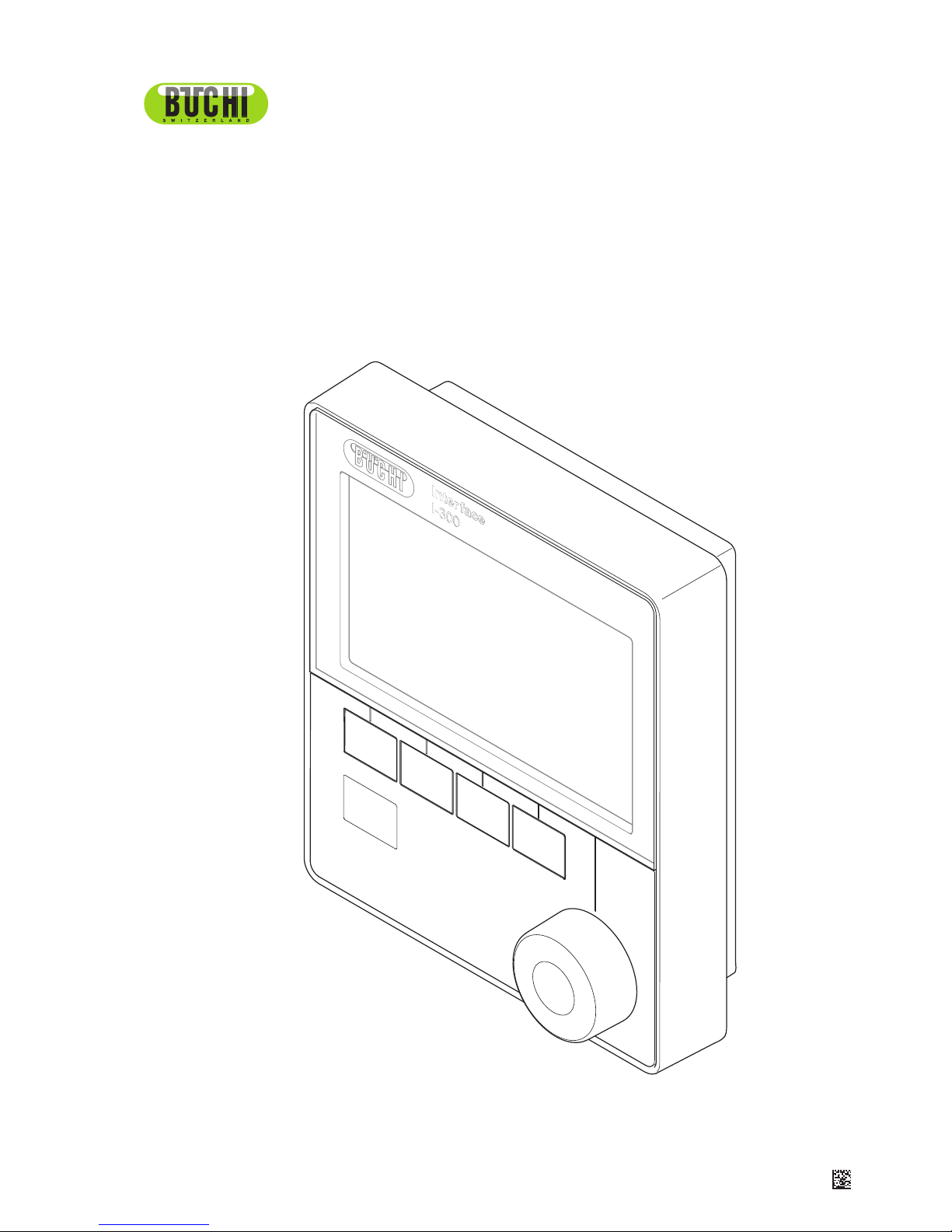
Interface I-300
Operation Manual
STOP
11593772D en
Page 2

Imprint
Product Identification:
Operation Manual (Original) Interface I-300
11593772
Publication date: 06.2017
BÜCHI Labortechnik AG
Meierseggstrasse 40
Postfach
CH-9230 Flawil 1
E-Mail: quality@buchi.com
BUCHI reserves the right to make changes to the manual as deemed necessary in the light of experience, especially with respect to structure, illustrations and technical detail.
This manual is copyrighted. Information from it may not be reproduced, distributed, or used for competitive purposes, nor made available to third parties. The manufacture of any component with the aid of this
manual without prior written agreement is also prohibited.
Page 3

BÜCHI Labortechnik AG Contents
Operation Manual Interface I-300 iii
Contents
1 About this document........................................................................................................... 6
1.1 Warning notices in this document........................................................................................................ 6
1.2 Symbols............................................................................................................................................... 6
1.2.1 Warning symbols .....................................................................................................................6
1.2.2 Mandatory directive symbols ...................................................................................................7
1.2.3 Other symbols..........................................................................................................................7
1.3 Available languages............................................................................................................................. 7
1.4 Trademarks.......................................................................................................................................... 7
2 Safety....................................................................................................................................8
2.1 Intended use........................................................................................................................................ 8
2.2 Use other than that intended ............................................................................................................... 8
2.3 Staff qualification ................................................................................................................................. 8
2.4 Residual risks ...................................................................................................................................... 9
2.4.1 Faults during operation ............................................................................................................ 9
2.5 Personal protective equipment ............................................................................................................ 9
2.6 Modifications........................................................................................................................................ 9
3 Product description........................................................................................................... 10
3.1 Description of function ....................................................................................................................... 10
3.2 Configuration ..................................................................................................................................... 10
3.2.1 Front view ..............................................................................................................................10
3.2.2 Rear view ............................................................................................................................... 11
3.2.3 VacuBox (connections).......................................................................................................... 12
3.2.4 LegacyBox (connections)....................................................................................................... 13
3.2.5 Display (touch-screen) ........................................................................................................... 15
3.2.6 Type plate .............................................................................................................................. 16
3.3 Navigating through the menu system ................................................................................................ 17
3.3.1 Main menu ............................................................................................................................. 17
3.3.2 Operating modes ...................................................................................................................18
3.3.3 Configuration..........................................................................................................................20
3.3.4 Libraries ................................................................................................................................. 23
3.4 Specifications supplied ...................................................................................................................... 24
3.4.1 Interface I-300........................................................................................................................24
3.4.2 VacuBox.................................................................................................................................24
3.4.3 LegacyBox ............................................................................................................................. 24
3.5 Technical data ................................................................................................................................... 25
3.5.1 Interface I-300........................................................................................................................25
3.5.2 VacuBox.................................................................................................................................25
3.5.3 LegacyBox ............................................................................................................................. 26
3.5.4 Ambient conditions.................................................................................................................26
3.5.5 Materials ................................................................................................................................26
4 Transport and storage ......................................................................................................27
4.1 Transport ........................................................................................................................................... 27
4.2 Storage .............................................................................................................................................. 27
Page 4

Contents BÜCHI Labortechnik AG
iv Operation Manual Interface I-300
5 Installation.......................................................................................................................... 28
5.1 Fitting the Interface I-300/I-300 Pro................................................................................................... 28
5.1.1 Mounting interface on Rotavapor R-300................................................................................ 28
5.1.2 Fitting interface unit on Vacuum Pump V-300 .......................................................................30
5.1.3 Mounting interface unit on laboratory stand (optional accessory).......................................... 31
5.1.4 Mounting interface unit on a wall bracket (optional accessory) .............................................32
5.2 Assembling the BUCHI distillation system......................................................................................... 33
5.2.1 Connecting communication cables to interface unit............................................................... 33
5.2.2 Overview: setting up communication connections................................................................. 34
5.2.3 Overview: setting up coolant tubing connections...................................................................35
5.2.4 Overview: setting up vacuum tubing connections..................................................................36
5.3 Connecting AutoDest sensor to vapor temperature sensor (optional accessory).............................. 37
5.4 Connecting foam sensor (optional accessory)................................................................................... 39
5.5 Connecting valve unit for external vacuum........................................................................................ 40
5.6 Operating I-300 and I-300 Pro in parallel........................................................................................... 40
6 Operation............................................................................................................................ 41
6.1 Navigating the menu.......................................................................................................................... 41
6.1.1 Selecting menu items............................................................................................................. 41
6.1.2 Entering parameter settings...................................................................................................42
6.1.3 Changing settings .................................................................................................................. 42
6.2 Performing distillation ........................................................................................................................ 44
6.2.1 Overview: typical distillation sequence ..................................................................................45
6.2.2 Basic functions.......................................................................................................................46
6.2.3 Performing manual distillation................................................................................................47
6.2.4 Performing timer-controlled distillation...................................................................................50
6.2.5 Drying the system after distillation ("Continuous pumping") .................................................. 53
6.2.6 Performing automatic distillation............................................................................................ 57
6.2.7 Drying the product..................................................................................................................59
6.3 Using the solvent library .................................................................................................................... 62
6.4 Activating eco mode .......................................................................................................................... 64
6.5 Setting hysteresis .............................................................................................................................. 65
6.6 Creating favorites............................................................................................................................... 66
7 Mobile connection .............................................................................................................67
7.1 Setting up BUCHI Connect Solution.................................................................................................. 67
7.2 Components of the BUCHI Connect Solution.................................................................................... 68
7.3 Requirements for local network settings............................................................................................ 68
7.4 Connecting interface unit to the LAN................................................................................................. 69
7.5 Handling data..................................................................................................................................... 69
7.6 Enabling interface unit for access to BUCHI Cloud ........................................................................... 71
7.7 Assigning IP addresses ..................................................................................................................... 72
7.8 Downloading and installing the BUCHI Rotavapor app ..................................................................... 72
7.9 Viewing the QR code......................................................................................................................... 72
7.10 Generating a password...................................................................................................................... 74
7.11 Connecting to the distillation system with the BUCHI Rotavapor app ............................................... 74
7.12 Scanning the QR code with your smartphone ................................................................................... 75
7.13 Activating push notifications .............................................................................................................. 76
7.14 Remotely retrieving process data ...................................................................................................... 77
7.15 Optional function: setting up a local server........................................................................................ 79
Page 5

BÜCHI Labortechnik AG Contents
Operation Manual Interface I-300 v
8 Cleaning and servicing .....................................................................................................80
8.1 Cleaning the casing/display............................................................................................................... 80
8.2 Performing a leak test........................................................................................................................ 80
8.3 Fitting GL14 cap nut with tube seal ................................................................................................... 81
8.4 Checking seals .................................................................................................................................. 82
8.5 Calibrating AutoDest sensor.............................................................................................................. 83
8.6 Calibrating the pressure sensor......................................................................................................... 83
8.6.1 Offset calibration.................................................................................................................... 84
8.6.2 Simple calibration................................................................................................................... 84
8.6.3 Loading factory calibration..................................................................................................... 85
9 Help with faults ..................................................................................................................86
9.1 Faults, possible causes and remedies............................................................................................... 86
9.2 Error messages ................................................................................................................................. 87
9.3 Customer service............................................................................................................................... 87
10 Taking out of service and disposal.................................................................................. 88
10.1 Taking out of service.......................................................................................................................... 88
10.2 Disposal ............................................................................................................................................ 88
11 Appendix ............................................................................................................................89
11.1 Solvent table...................................................................................................................................... 89
11.2 Spare parts and accessories ............................................................................................................. 91
11.2.1 Accessories............................................................................................................................91
11.2.2 Wear parts .............................................................................................................................92
11.2.3 Spare parts ............................................................................................................................93
11.3 Health and safety approval................................................................................................................ 94
11.4 Health and safety............................................................................................................................... 95
Page 6
1 | About this document BÜCHI Labortechnik AG
6/96 Operation Manual Interface I-300
1 About this document
These operating instructions describe the Interface I-300 at the time supplied. They
are an integral part of the product and contain important information that is necessary
for safe operation and maintenance.
These operating instructions apply to all variants of the Interface I-300 and are
intended primarily for laboratory staff.
u To ensure safe and trouble-free operation, read these operating instructions
before starting up the device and follow the guidance they contain.
u Keep the operating instructions somewhere near to the device.
u Pass on the operating instructions to any subsequent owner or user.
BÜCHI Labortechnik AG accepts no liability whatsoever for any faults or damage that
result from the failure to follow these operating instructions.
u If you still have any questions after reading these operating instructions, please
contact BÜCHI Labortechnik AG Customer Service. Contact details for your local
agents can be found on the Internet at http://www.buchi.com.
1.1 Warning notices in this document
Warning notices warn you of dangers that can occur when handling the device. There
are four danger levels, each identifiable by the signal word used.
Signal word Meaning
DANGER Indicates a danger with a high level of risk which could result in
death or serious injury if not prevented.
WARNING Indicates a danger with a medium level of risk which could result in
death or serious injury if not prevented.
CAUTION Indicates a danger with a low level of risk which could result in
minor or medium-severity injury if not prevented.
IMPORTANT Indicates a danger that could result in damage to property.
1.2 Symbols
The following symbols may be displayed in this instruction manual or on the device:
1.2.1 Warning symbols
Symbol Meaning Symbol Meaning
General warning Corrosive substance
Dangerous electrical voltage Flammable substance
Biological hazard Potentially explosive atmos-
phere
Breakable items Dangerous gases
Page 7
BÜCHI Labortechnik AG About this document | 1
Operation Manual Interface I-300 7/96
Symbol Meaning Symbol Meaning
Hot surface Health-harming or irritant
substances
Risk of hand injury Strong magnetism
1.2.2 Mandatory directive symbols
Symbol Meaning Symbol Meaning
Wear safety goggles Wear protective clothing
Wear protective gloves Heavy load, do not lift with-
out assistance
1.2.3 Other symbols
NOTE
This symbol draws attention to useful and important information.
R This character draws attention to a requirement that must be met before the
instructions below are carried out.
u This character indicates an instruction that must be carried out by the user.
5 This character indicates the result of a correctly carried out instruction.
1.3 Available languages
These operating instructions were originally produced in German and have been
translated into several other languages. The translations are available on the
enclosed CD or can be obtained as a PDF file via http://www.buchi.com.
1.4 Trademarks
Product names and registered or unregistered trademarks that are used in this
instruction manual are used only for identification and remain the property of the
owner in each case.
For example, Rotavapor® is a registered trademark of BÜCHI Labortechnik AG.
Page 8

2 | Safety BÜCHI Labortechnik AG
8/96 Operation Manual Interface I-300
2 Safety
2.1 Intended use
The Interface I-300 is intended for indicating vacuum within an operating range of
0mbar to ambient atmospheric pressure. The measurement and regulation of the
vacuum is performed by means of a VacuBox. The Interface I-300 has been designed
and built as an item of laboratory equipment and can be used in conjunction with the
following devices:
Distillation apparatus, especially rotary evaporators
Vacuum-drying cabinets
Vacuum pumps
Recirculating chiller
2.2 Use other than that intended
Use of any kind other than that described in the section Chapter2.1 "Intended use",
page8 and any application that does not comply with the technical specifications
(see Chapter3.5 "Technical data", page25) constitutes use other than that intended.
In particular, the following applications are not permissible:
Use of the device in areas that require apparatus that is safe to use in potentially
explosive atmospheres.
Use as a calibration device for other equipment.
Operation at pressures above atmospheric
Damage or hazards attributable to use of the product other than as intended are
entirely at the risk of the user alone.
2.3 Staff qualification
Unqualified persons are unable to identify risks and are therefore exposed to greater
dangers.
The device may only be operated by suitably qualified laboratory staff.
These operating instructions are aimed at the following target groups:
Users
Users are persons that meet the following criteria:
They have been instructed in the use of the device.
They are familiar with the contents of these operating instructions and the
applicable safety regulations and apply them.
They are able on the basis of their training or professional experience to assess
the risks associated with the use of the device.
Page 9

BÜCHI Labortechnik AG Safety | 2
Operation Manual Interface I-300 9/96
Operator
The operator (generally the laboratory manager) is responsible for the following
aspects:
The device must be correctly installed, commissioned, operated and serviced.
Only suitably qualified staff may be assigned the task of performing the operations
described in these operating instructions.
The staff must comply with the locally applicable requirements and regulations for
safe and hazard-conscious working practices.
Safety-related incidents that occur while using the device should be reported to the
manufacturer (quality@buchi.com).
BUCHI service technicians
Service technicians authorized by BUCHI have attended special training courses and
are authorized by BÜCHI Labortechnik AG to carry out special servicing and repair
measures.
2.4 Residual risks
The device has been developed and manufactured using the latest technological
advances. Nevertheless, risks to persons, property or the environment can arise if the
device is used incorrectly.
Appropriate warnings in this manual serve to alert the user to these residual dangers.
2.4.1 Faults during operation
If a device is damaged, sharp edges, moving parts or exposed electrical wires can
cause injuries.
u Regularly check device for visible damage.
u If faults occur, switch off the device immediately, unplug the power cord and
inform the operator.
u Do not continue to use devices that are damaged.
2.5 Personal protective equipment
Depending on the application, hazards due to heat and/or corrosive chemicals may
arise.
u Always wear appropriate personal protective equipment such as safety goggles,
protective clothing and gloves.
u Make sure that the personal protective equipment meets the requirements of the
safety data sheets for all chemicals used.
2.6 Modifications
Unauthorized modifications may impair safety and lead to accidents.
u Use only genuine BUCHI accessories, spare parts and consumables.
u Technical modifications to the device or accessories should only be carried out
with the prior written approval of BÜCHI Labortechnik AG and only by authorized
BUCHI technicians.
BUCHI accepts no liability whatsoever for damage arising as a result of unauthorized
modifications.
Page 10

3 | Product description BÜCHI Labortechnik AG
10/96 Operation Manual Interface I-300
3 Product description
3.1 Description of function
The Interface I-300 is designed for indicating, adjusting and controlling the complete
distillation system. The Interface I-300 settings enable precise specification of the
individual process parameters.For example:
Rotation speed of the evaporating flask
Specified temperature of the heating bath
Specified temperature of the coolant
Specified vacuum pressure
Duration of the distillation process
The pressure is measured and regulated by the associated VacuBox. Measurement
is independent of the solvent used.
3.2 Configuration
3.2.1 Front view
STOP
1
3
2
4
Fig.1: Front view of Interface I-300
1 Display 3 Navigation control
2 STOP button (emergency stop) 4 Function buttons
Page 11
BÜCHI Labortechnik AG Product description | 3
Operation Manual Interface I-300 11/96
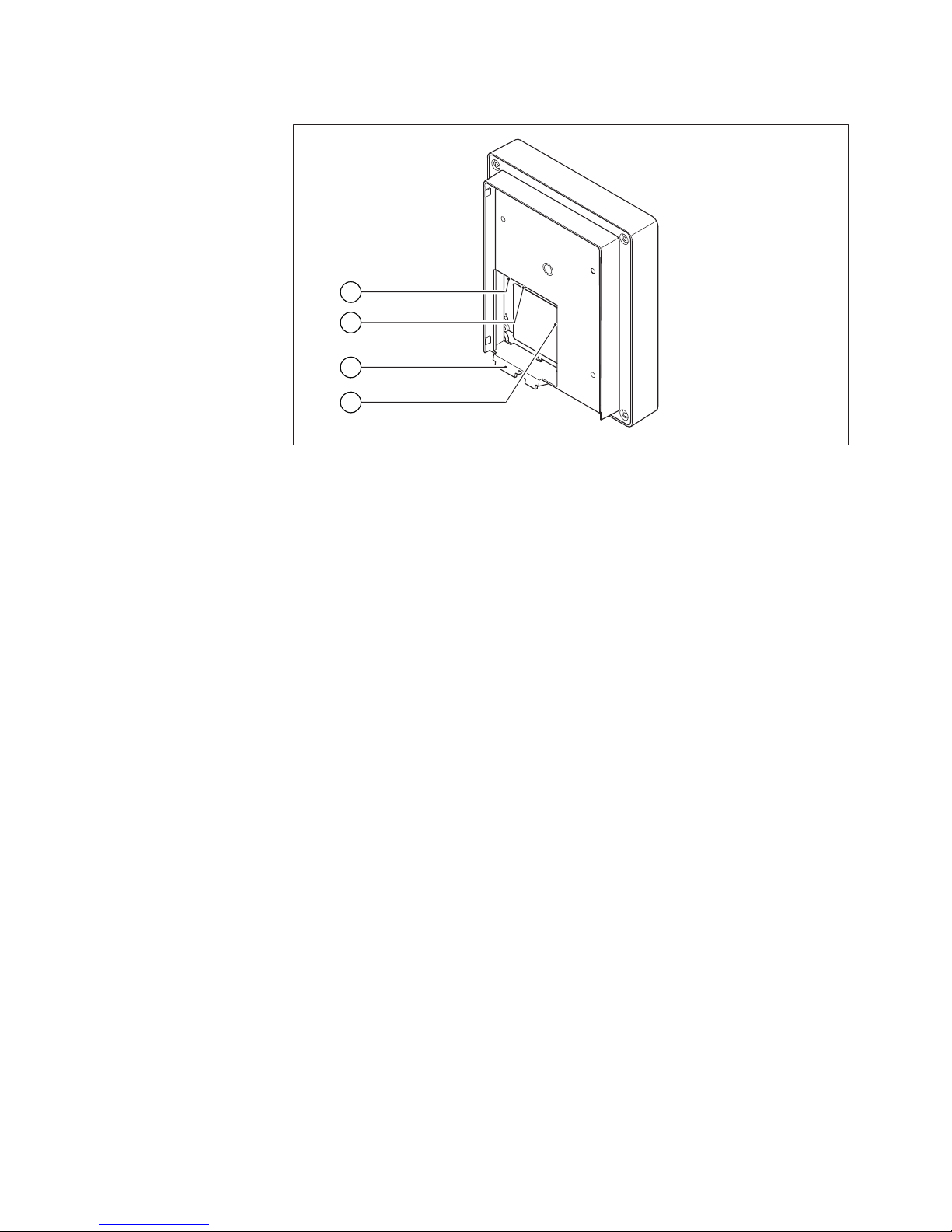
3.2.2 Rear view
3
4
1
2
Fig.2: Rear view of Interface I-300
1 LAN port 3 Locating lug for bracket
2 Standard BUCHI communication port
(COM)
4 MicroSD card (not used)
Page 12
3 | Product description BÜCHI Labortechnik AG
12/96 Operation Manual Interface I-300
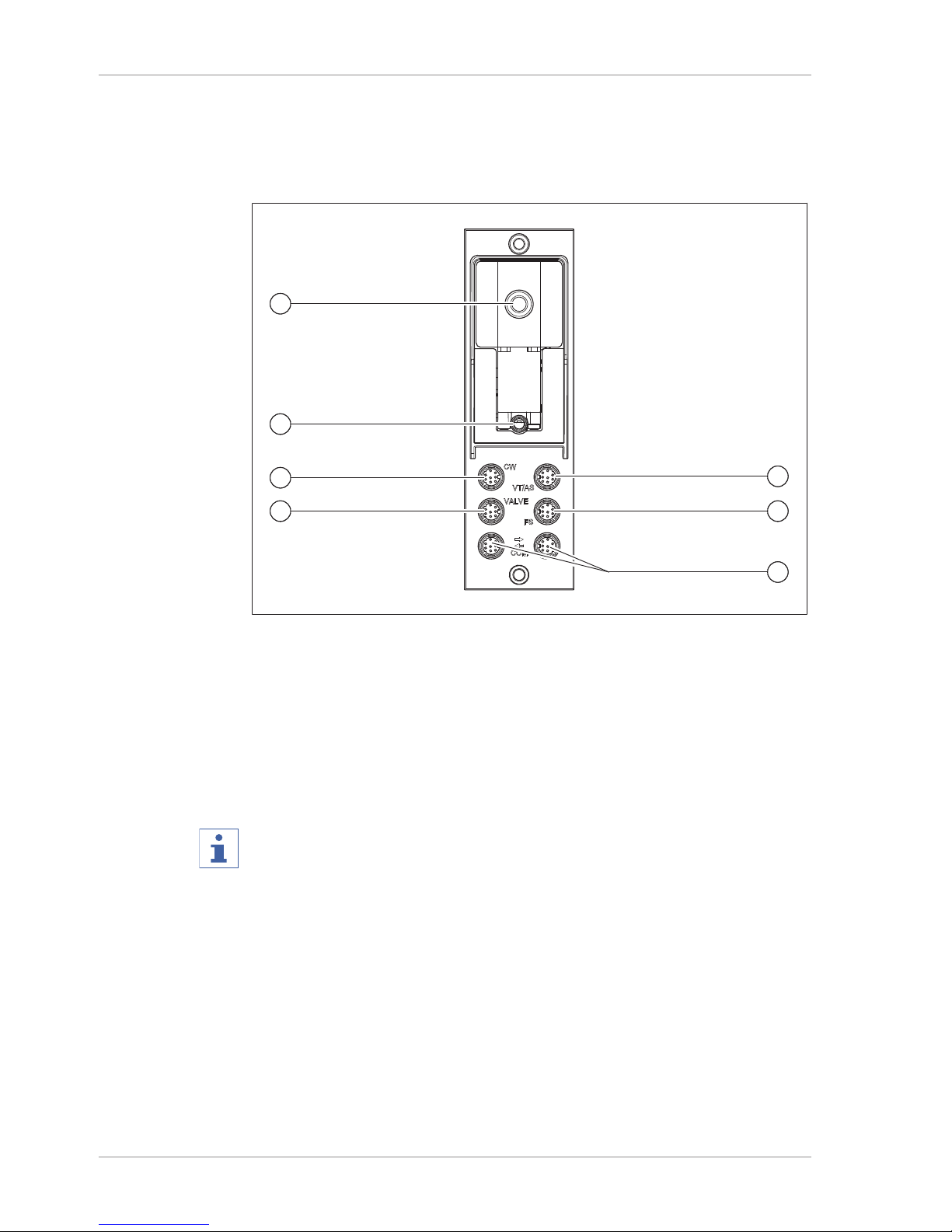
3.2.3 VacuBox (connections)
Other BUCHI laboratory equipment is connected to the Interface I-300 in series
together with the VacuBox. The individual devices are connected to one another via
the standard BUCHI communication port (7). See Chapter5.2.2 "Overview: setting up
communication connections", page34.
1
1
3
4
5
6
7
1
2
Fig.3: Connections on the VacuBox
1 Vacuum connection 5 Connection for vapor temperature/
AutoDest sensor (VT/AS)
2 Venting valve/inert gas connection
(optional)
6 Foam sensor connection (FS)
3 Water coolant valve connection (CW) 7 Standard BUCHI communication port
(COM)
4 Connection for valve unit or straight-
way valve (VALVE)
NOTE
Connecting VacuBox with R-220 Pro:
If the Interface I-300 Pro and the VacuBox are operated in the Rotavapor R-220 Pro
system, the following points should be noted: The external valves must always be
connected to the Rotavapor R-220 Pro even if there is an alternative connection on
the VacuBox.
Page 13
BÜCHI Labortechnik AG Product description | 3
Operation Manual Interface I-300 13/96
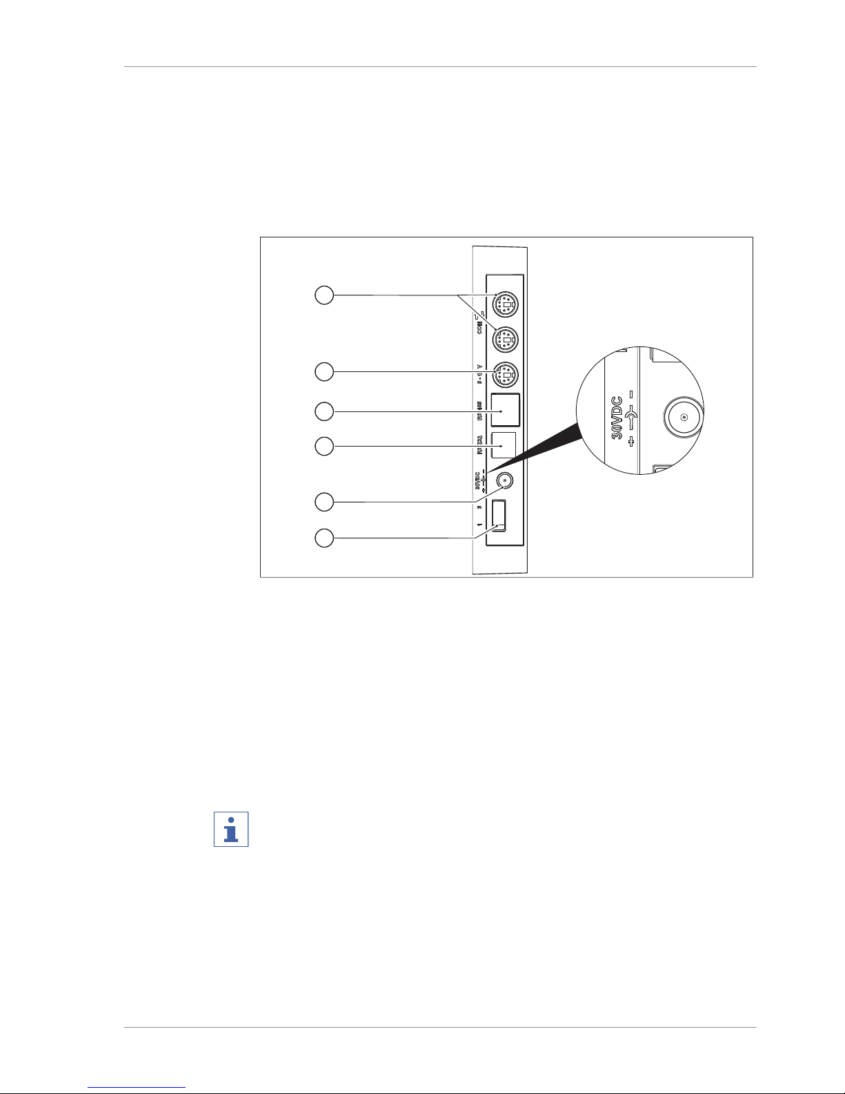
3.2.4 LegacyBox (connections)
Connection of a LegacyBox is required whenever legacy BUCHI laboratory equipment is to be controlled via the Interface I-300. The LegacyBox is connected to the
distillation system using a standard BUCHI communication cable and has other
connection options such as an RS-485 communication port. There is also the option
of incorporating pumps of other makes in the Rotavapor system and controlling them
via the interface. In that case, the pump requires a 0 – 10 V input.
The LegacyBox is fixed to a Rotavapor R-300 or a laboratory stand clamp.
2
4
3
1
6
5
Fig.4: Connections on the LegacyBox
1 Standard BUCHI communication port
(COM)
4 RS-232 (not used)
2 0 – 10 V communication port – for
connecting pumps of other makes
5 External power supply – for genuine
BUCHI mains adaptor, 30 V, 30 W
(see Chapter11.2.1 "Accessories",
page91)
3 RS-485 communication port – for
connecting legacy BUCHI laboratory
equipment (Vacuum Pumps V-700 /
V-710, Rotavapors: R-210 / R-215,
Recirculating Chiller F-1xx)
6 On/Off switch
NOTE
The external power supply is only necessary if the LegacyBox is not connected to a
Rotavapor or a vacuum pump and is used for other vacuum control applications
instead. Otherwise the vacuum pump or the Rotavapor supplies the LegacyBox with
power.
0 – 10 V communication port
This connection comprises a 0 – 10 V output for connecting pumps of other makes
and electrically isolated relay contacts. There is also a valve control contact.
Page 14

3 | Product description BÜCHI Labortechnik AG
14/96 Operation Manual Interface I-300
Fig.5: 8-pin MiniDin pin assignment, view of socket
Pin
8-pin notation
Symbol Description
1 Ground Ground connection for valve and 10 V
output
2 Valve Vacuum valve connection
3 Spare
4 10 V output 0 – 10 V (max. 20 mA, min. 500 Ohm)
5 Relay In Max. 30 V 2 A, electrically isolated
6 Spare
7 Spare
8 Relay Out Max. 30 V 2 A, electrically isolated
S Shield Shield, connected to ground
Page 15
BÜCHI Labortechnik AG Product description | 3
Operation Manual Interface I-300 15/96
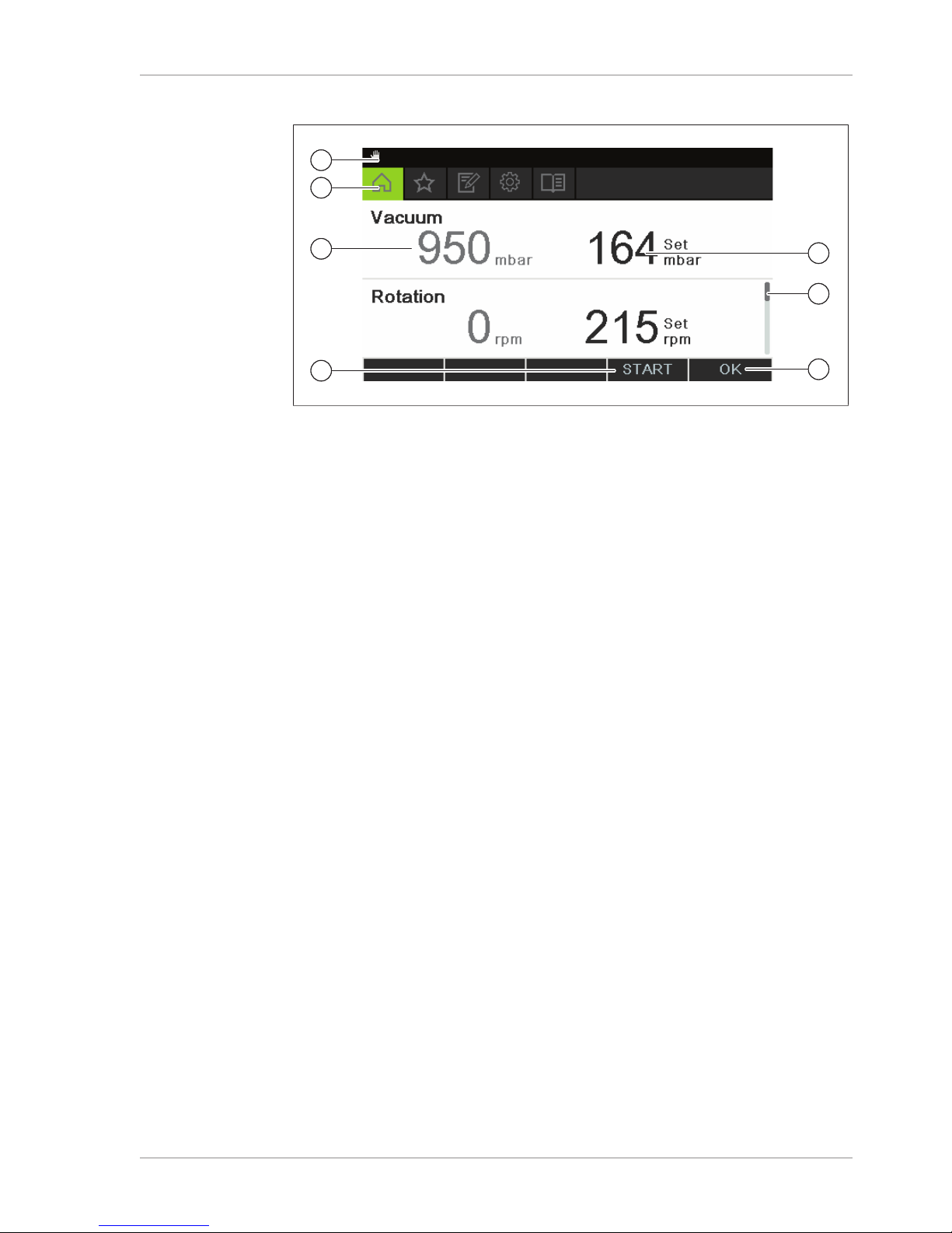
3.2.5 Display (touch-screen)
1
2
3
4
1
5
6
7
1
1
Fig.6: Display layout
1 Status bar 5 Current setting (e.g. vacuum)
2 Menu bar 6 Scroll bar
3 Current reading (e.g. vacuum) 7 Function activated if navigation
control is pressed
4 Functions of the function buttons
below (context-dependent)
Page 16
3 | Product description BÜCHI Labortechnik AG
16/96 Operation Manual Interface I-300
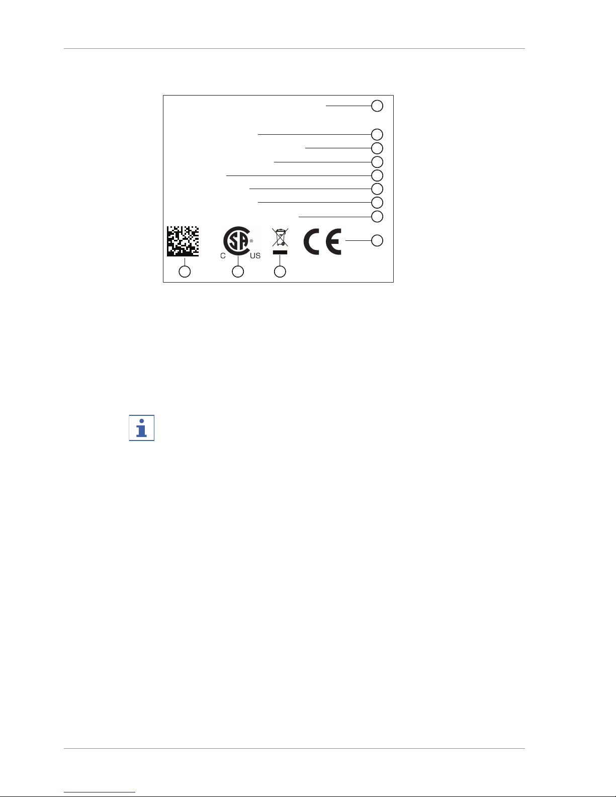
3.2.6 Type plate
The type plate is on the rear of the Interface I-300.
BÜCHI Labortechnik AG
CH-9230 Flawil/Switzerland
Type: I-300
SN: 1000000000
Volt: 30 VDC
Frequ.:
Power: 3 W
Built: 2014
Made in Switzerland
3
7
2
1
5
4
6
8
9
1011
9
Fig.7: Type plate (example)
1 Company name and address 7 Year of manufacture
2 Device name 8 Country of manufacture
3 Serial number 9 Approvals
4 Input voltage 10 Symbol for "Do not dispose of as
household waste"
5 Frequency 11 Product code
6 Maximum power rating
NOTE
The VacuBox and the LegacyBox each have their own type plate on the rear.
Page 17

BÜCHI Labortechnik AG Product description | 3
Operation Manual Interface I-300 17/96
3.3 Navigating through the menu system
3.3.1 Main menu
Highest menu level
Symbol Meaning Sub-items
Home page Process control
parameters
Favorites Bookmarks for fre-
quently used individual
starting points
Operating modes Manual
Timer
Continuous pumping
AutoDest
Drying
Configuration Servicing
Settings
Service
System information
Libraries Solvent library
Consumables
Page 18

3 | Product description BÜCHI Labortechnik AG
18/96 Operation Manual Interface I-300
3.3.2 Operating modes
Fig.8: "Operating modes" selected on main menu of Interface I-300
The Interface I-300 distinguishes between the following operating modes for a
distillation system:
Operating mode Purpose Consists of
Manual Carrying out distil-
lation with manually
set parameters
User-definable configuration of specified
settings for the individual process
parameters:
Vacuum
Evaporating flask rotation
Heating bath temperature
Coolant temperature
The actual values for the above
parameters are displayed, plus:
Vapor temperature
Timer Carrying out a dis-
tillation process
with manually set
parameters which
is to be stopped after a set time has
elapsed
User-definable configuration of specified
settings for the timer and individual
process parameters:
See "Manual"
Timer
Continuous
pumping
Drying the system
after distillation
Continuous operation of pump without
option of setting pressure.
AutoDest Carrying out auto-
matic single or
multi-stage distillation with specified
settings for the vacuum continuously
adjusted by the
system
Precondition: AutoDest sensor
connected to the system and supplying
readings:
Coolant inlet temperature
Coolant outlet temperature
Vapor temperature
The algorithm continuously adjusts the
specified settings for the pressure.
Process stops automatically as soon as
distillation is completed.
Page 19

BÜCHI Labortechnik AG Product description | 3
Operation Manual Interface I-300 19/96
Operating mode Purpose Consists of
Drying Post-drying of con-
tents of evaporating
flask.
Drying of evaporating flask contents.
Evaporating flask rotates in alternating
directions for a defined period of time.
User-definable configuration of specified
settings for the individual process
parameters:
See "Manual"
Timer
Rotation interval
Page 20

3 | Product description BÜCHI Labortechnik AG
20/96 Operation Manual Interface I-300
3.3.3 Configuration
Fig.9: "Configuration" selected on main menu of Interface I-300
The menu item "Configuration" on the main menu of the Interface I-300 offers the following options:
Servicing
"Servicing" provides access to information on seal servicing and the option of carrying
out a leak test on the distillation system.
Action Option Explanation
Leak test START For carrying out a leak test on the distil-
lation system.
Seal servicing Information Hours of rotation since last service.
Facility for resetting rotation hours
counter.
Settings
The "Settings" submenu provides the facility for changing basic settings on the
distillation system.
Action Option Explanation
Mobile connection
QR code
Display Interface shows QR code for the
connected distillation system, see
Chapter7.9 "Viewing the QR code",
page72.
Mobile connection
password
Display For viewing password and entering on
mobile device (alternative to QR code)
On finish: vent
system
On/Off System is vented after automatic or
manual termination of distillation.
On start: start rotation
On/Off Evaporating flask starts rotating when
distillation is started.
On finish: stop rotation
On/Off Evaporating flask stops rotating after
automatic or manual termination of
distillation.
On start: immerse
flask
On/Off Evaporating flask is automatically
immersed in the heating bath when d
istillation is started.
On finish: lift out
flask
On/Off Evaporating flask is automatically lifted
out of the heating bath after automatic or
manual termination of distillation.
On finish: stop
heating
On/Off Heating of heating bath stops after
automatic or manual termination of d
istillation.
Page 21

BÜCHI Labortechnik AG Product description | 3
Operation Manual Interface I-300 21/96
Action Option Explanation
On finish: stop
cooling
On/Off The Recirculating Chiller F-3xx automati-
cally switches off (after a run-on period 5
minutes) after automatic or manual
termination of distillation.
On finish: play
sound
On/Off An audible signal is sounded after
automatic or manual termination of d
istillation.
Pressure hysteresis
Entry of pressure Entry of figure for the maximum
allowable difference between the actual
vacuum and the specified figure before
the vacuum pump switches on again?
Language Choice of language
used for Interface
display
English, Deutsch, Francais, Italiano,
Espanol, Russian, Portugues, Japanese,
Chinese, Indonesian, Korean
Button tone On/Off A beep sounds when a function button or
the navigation control is pressed.
Seal servicing information
On/Off The interface shows information about
regular servicing of the system seals.
The message appears periodically after
every 500 hours of rotation.
Temperature unit Choice of unit for
indication of temperatures
°C(Celsius), °F(Fahrenheit) or
K(Kelvin)
Pressure unit Choice of unit for
indication of (negative) pressure
hPa (hectopascals), mbar (millibars),
torr (=mmHg), mmHg (millimeters of
mercury)
Height above sea
level
Entry of figure Altitude of location above mean sea
level: max.4000m.
For determination of max. allowable
pressure when working with the solvent
library.
Max. permissible
pressure
Entry of figure Max. pressure level present in the
system: max. 1400 mbar.
Max. pump delivery
Entry of figure Max. pump speed in %: 10–100%.
Display brightness
Entry of figure Display illumination level in %:
0–100%.
eco mode On/Off and entry of
figures
Settings for eco mode in respect of
"Delay" (minutes), "Bath reduction" (temperature), "Coolant increase"
(temperature)
Network Entry of details System name
DHCP: Yes/No
Network addresses for "Device IP
address", "Gateway", "Subnet mask",
"Server IP address"
BUCHI Cloud: Yes/No
Delete APP connection
Confirmation question
All connections settings entered for the
device are reset.
Page 22

3 | Product description BÜCHI Labortechnik AG
22/96 Operation Manual Interface I-300
Service
The "Service" submenu provides options for adjusting/calibrating the connected
measuring instruments.
Action Option Consists of
Calibrate AutoDest sensor
Perform calibration Calibration sequence between the two
condenser sensors. Precondition: the
two condenser sensors are at the same
temperature. See Chapter8.5
"Calibrating AutoDest sensor", page83.
Pressure offset Entry of reference
figure for measuring system pressure
The pressure inside the distillation
system is measured by a reference
sensor. That reading is entered as the
reference figure for the system's internal
pressure sensor. See Chapter8.6.1
"Offset calibration", page84.
Pressure calibration
Calibration of pressure sensor and
entry of reference
pressure
The pressure sensor is calibrated in five
stages for the set pressures of approx.
950 mbar (ambient pressure), 800 mbar,
600 mbar, 400 mbar, 200 mbar and 10
mbar. See Chapter8.6.2 "Simple
calibration", page84.
Loading factory
calibration
Calibration reset The current pressure sensor calibration
data is overwritten by the factory
calibration settings. See Chapter8.6.3
"Loading factory calibration", page85.
System information
The submenu "System information" provides details of the laboratory equipment
connected and on network connection diagnosis.
Page 23

BÜCHI Labortechnik AG Product description | 3
Operation Manual Interface I-300 23/96
3.3.4 Libraries
Fig.10: "Libraries" selected on main menu
The menu item "Libraries" on the main menu of the Interface I-300 offers access
to two libraries:
Solvent library
Wearing parts
Solvent library
The Interface I-300 has an internal solvent library. That library lists the most common
solvents (e.g. ethanol) in alphabetical order. For each solvent, the library contains an
algorithm that calculates the optimum vacuum setting from the actual figures for
heating bath temperature and coolant temperature. The specified vacuum setting is a
dynamic figure that alters automatically according to the current temperatures of
coolant and heating bath until they too have reached their specified settings.
Fig.11: Entries in the solvent library
NOTE
The individual solvents can be saved as favorites. A distillation process can be
started directly from the solvent library.
NOTE
When the heating bath and the recirculating chiller are connected, the actual figures
are automatically applied. If equipment of a different make is connected, the set
temperatures on the devices concerned have to be entered as specified settings on
the interface.
Wearing parts
The Interface I-300 offers a list containing a selection of the wearing parts for the
BUCHI Rotavapor system. The list is divided into two columns. The left-hand column
itemizes the wearing parts in alphabetical order. The right-hand column shows the
order numbers for the wearing parts.
Page 24

3 | Product description BÜCHI Labortechnik AG
24/96 Operation Manual Interface I-300
3.4 Specifications supplied
3.4.1 Interface I-300
Component Quantity sup-
plied
Interface I-300 1
Device bracket assembly:
Screw, M6x16 1
Torx key, Tx20 1
Torx key, Tx30 1
Holder 1
Metal plate 1
Knurled-head screw 1
3.4.2 VacuBox
Component Quantity sup-
plied
VacuBox 1
VacuBox accessory set:
Screw, M4x20 2
Torx key, Tx20 1
MiniDIN lead, 0.3 m 1
NOTE
The VacuBox is an essential requirement for use of the Interface I-300/I-300 Pro.
3.4.3 LegacyBox
Component Quantity sup-
plied
LegacyBox 1
LegacyBox accessory set:
Screw, M4x30 2
Screw, M4x50 2
Torx key, Tx20 1
MiniDIN lead, 0.3 m 1
Page 25

BÜCHI Labortechnik AG Product description | 3
Operation Manual Interface I-300 25/96
3.5 Technical data
3.5.1 Interface I-300
Dimensions (W x H x D) 121 x 141 x 50 mm
Weight 400 g
Power supply voltage 30 VDC ±5 %
Power consumption 3 W
Enclosure rating IP21
Approval CE/CSA
3.5.2 VacuBox
Dimensions (W x H x D) 50 x 167 x 57 mm
Weight 400 g
Power supply voltage 30 VDC ±5 %
Power consumption 8 W
Solenoid valve power supply 24 V
Measurement range 1400 – 0 mbar
Regulating range Ambient pressure – 0 mbar
Measurement accuracy ± 2 mbar (after calibration at constant
temperature)
Temperature compensation 0.07 mbar/K
Hysteresis Automatic or 1 – 200 mbar
Vacuum connection GL14
Enclosure rating IP21
Approval CE/CSA
Page 26

3 | Product description BÜCHI Labortechnik AG
26/96 Operation Manual Interface I-300
3.5.3 LegacyBox
Dimensions (W x H x D) 50 x 167 x 28 mm
Weight 200 g
Power supply voltage 30 VDC ±5 %
Power consumption 8 W
Enclosure rating IP21
Approval CE/CSA
3.5.4 Ambient conditions
Max. altitude above sea level 2000 m
Ambient temperature 5 - 40 °C
Maximum relative humidity 80 % for temperatures up to 31 °C
decreasing linearly to 50 % at 40 °C
The laboratory equipment described in this document may only be used in indoor
areas.
3.5.5 Materials
Component Material
Pressure foil Polyester
Casing PBT
Vent tube connection PPS
Pressure sensor Al₂O₃ 96%
Page 27

BÜCHI Labortechnik AG Transport and storage | 4
Operation Manual Interface I-300 27/96
4 Transport and storage
4.1 Transport
IMPORTANT
Risk of breakage due to incorrect transportation
u Make sure that all parts of the device are safely packed in such a way as to
prevent breakage, ideally in the original box.
u Avoid sharp movements during transit.
u After transportation, check the device for damage.
u Damage that has occurred in transit should be reported to the carrier.
u Keep packing for future transportation.
4.2 Storage
u Make sure that the ambient conditions are complied with (see Chapter3.5
"Technical data", page25).
u Wherever possible, store the device in its original packaging.
u After storage, check the device for damage and replace if necessary.
Page 28

5 | Installation BÜCHI Labortechnik AG
28/96 Operation Manual Interface I-300
5 Installation
5.1 Fitting the Interface I-300/I-300 Pro
The Interface I-300/I-300 Pro can be mounted on one of the following BUCHI
laboratory devices:
Rotavapor R-300
Vacuum Pump V-300
Rotavapor R-220 Pro
Alternatively, the Interface I-300/I-300 Pro can be mounted separately on a laboratory
stand, see Chapter5.1.3 "Mounting interface unit on laboratory stand (optional
accessory)", page31.
5.1.1 Mounting interface on Rotavapor R-300
The Interface I-300 can be mounted and connected up on the vertically adjustable
arm of the Rotavapor R-300.
Tools required: Torx keys Tx20 and Tx30
1
3
2
Fig.12: Handle of Rotavapor R-300
1 Cover 3 Fixing screw for cover
2 Communication cables
u Remove the screw on the underside of the vertically adjustable arm (3) using a
Torx key and remove the cover (1) from the top of the arm.
u Remove the pre-fitted communication cable (2) from the cover.
Page 29
BÜCHI Labortechnik AG Installation | 5
Operation Manual Interface I-300 29/96
2
3
4
6
5
1
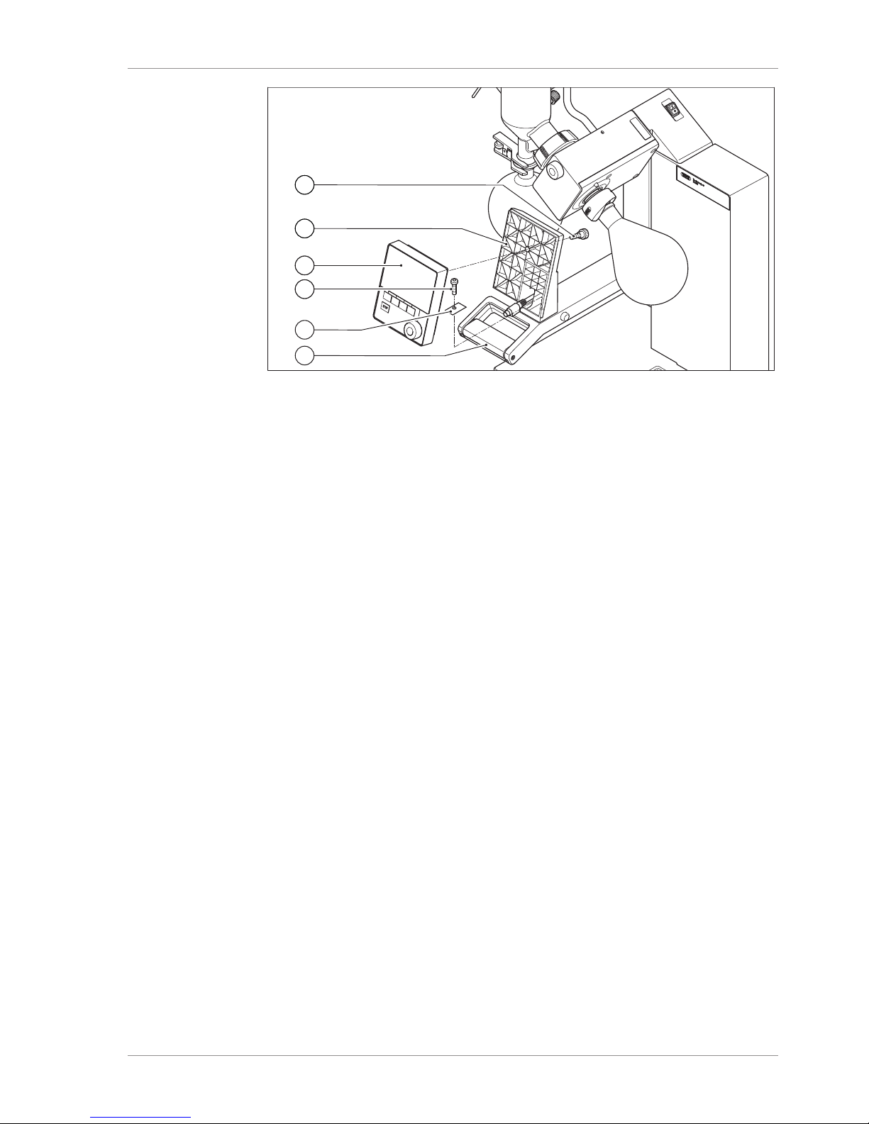
Fig.13: Fitting the holder and interface unit on the handle
1 Knurled-head screw 4 Fixing screw for holder
2 Holder for interface unit 5 Metal plate
3 Interface unit 6 Rotavapor arm and handle
u Position the holder (2) for the interface unit on the Rotavapor arm (6). At the same
time, feed the communication cable through the bottom hole in the holder.
u Fix the holder to the Rotavapor arm with a screw (4). When doing so, pass the
screw through the hole in the metal plate (5).
u Connect the communication cable to the COM port on the rear of the interface
unit.
u Position the interface unit (3) on the holder and fix it in place using the knurled-
head screw (1) supplied. When doing so, make sure that the communication cable
is not trapped.
Page 30

5 | Installation BÜCHI Labortechnik AG
30/96 Operation Manual Interface I-300
5.1.2 Fitting interface unit on Vacuum Pump V-300
1
4
5
6
7
2
3
Fig.14: Fitting interface unit on Vacuum Pump V-300
1 Interface unit 5 Casing front
2 Fixing screw for holder 6 Knurled-head screw
3 Metal plate 7 Holder
4 Rubber plug and threaded hole
Tools required:
Torx key Tx30
The Interface I-300 can be mounted on the top of the Vacuum Pump V-300 using a
holder.
u Remove the rubber plug (4) from the top panel of the vacuum pump. Use a
screwdriver if necessary.
Underneath the rubber plug is a threaded hole for a screw.
u Position the holder (7) over the threaded hole (4) and fix it in place using the screw
(2) supplied. When doing so, pass the screw through the hole in the metal plate
(3).
u Feed the communication cable through the holder from the rear and connect it to
the COM port on the back of the interface unit.
u Position the interface unit (1) on the holder and fix it in place using a knurled-head
screw (6) inserted from the back.
Page 31

BÜCHI Labortechnik AG Installation | 5
Operation Manual Interface I-300 31/96
5.1.3 Mounting interface unit on laboratory stand (optional accessory)
2
1
4
3
5
Fig.15: Mounting interface unit on laboratory stand
1 Holder for interface unit 4 Knurled-head screw
2 Interface unit 5 T-screw
3 Laboratory stand
The Interface I-300 can also be mounted on a laboratory stand using a holder.
u Position the holder (1) on the laboratory stand (3) and fix it in place using the
T-screw (5).
u Position the interface unit (2) on the flat face (1) of the holder and fix it in place
using a knurled-head screw (4).
Page 32

5 | Installation BÜCHI Labortechnik AG
32/96 Operation Manual Interface I-300
5.1.4 Mounting interface unit on a wall bracket (optional accessory)
STOP
2
1
4
5
6
3
Fig.16: Two-piece wall bracket for interface unit
1 Front plate of wall bracket 4 Rear plate of wall bracket
2 Interface unit 5 Slot in rear plate
3 Fixing screws for interface unit 6 Lug on front plate
The Interface I-300 can also be mounted directly onto a plastered or tiled wall or a
laboratory fume hood with the aid of a wall bracket.
u Position the rear plate (4) of the two-part wall bracket on the wall. Note: the word
"UP" stamped in the rear plate must be at the top.
u Option 1: peel protective foil off the back of the plate and press the plate firmly
against the wall/glass panel in the desired position so it is held in place by the
self-adhesive pad.
u Option 2: mark the positions of the four holes in the rear plate, drill four holes in
the wall in those positions and fix the plate to the wall using screws.
u Position the interface unit (2) on the outer face of the front plate (1) and fix it in
place using three screws (3).
u Fit the front plate together with interface unit onto the rear plate. As you do so,
locate the lugs (6) on the front plate in the slots (5) on the rear plate and then
press the front plate down.
Page 33

BÜCHI Labortechnik AG Installation | 5
Operation Manual Interface I-300 33/96
5.2 Assembling the BUCHI distillation system
In order to use the Interface I-300/I-300 Pro to best effect, we recommend that it is
used together with the following devices:
3
4
5
1
3
4
5
Fig.17: Typical application (example)
1 Recirculating Chiller F-3xx 4 Vacuum Pump V-300
2 Rotavapor R-300 with heating bath
B-305 or B-301
5 Interface I-300
3 VacuBox
The F-3xx is a recirculating chiller with a sealed circulation system. It is available in
various capacity ratings.
The Interface I-300/I-300 Pro together with the VacuBox can be used to control and
monitor the vacuum. It can control the Rotavapor, the Vacuum Pump V-300 and the
Recirculating Chiller F-3xx.
The Vacuum Pump V-300 is a diaphragm pump designed for evacuating laboratory
apparatus. It can be operated either as a standalone device or combined with optional
accessories such as an interface unit and a secondary condenser to form a complete
vacuum system. The laboratory equipment to be evacuated is connected to the
vacuum pump and the VacuBox by means of vacuum tubing. See Chapter5.2.4
"Overview: setting up vacuum tubing connections", page36.
Data communication between the laboratory equipment takes place via the
communication ports. See Chapter5.2.2 "Overview: setting up communication
connections", page34.
The coolant circulates around the distillation system through a separate circulation
system. See Overview: setting up coolant tubing connections.
5.2.1 Connecting communication cables to interface unit
The communication connections between the Interface I-300, the VacuBox and the
other BUCHI laboratory equipment are established using the standard BUCHI
communication cable (with green connector). The corresponding connection sockets
Page 34

5 | Installation BÜCHI Labortechnik AG
34/96 Operation Manual Interface I-300
are on the rear panels of the devices and are marked "COM" for identification. Details
of the precise positions of the connection sockets are provided in the operating
instructions for the devices.
For connection options on the Interface I-300 see Chapter3.2.2 "Rear view",
page11.
For connection options on the VacuBox see Chapter3.2.3 "VacuBox
(connections)", page12.
5.2.2 Overview: setting up communication connections
The laboratory apparatus can be connected in any order. Important: as well as the
Interface I-300/I-300 Pro, a VacuBox also has to be connected.
Below is an example of the connections between the laboratory apparatus.
Vacu
Box
Recirculating
Chiller F-3XX
Interface I-300/
I-300 Pro
Rotavapor
R-300
Vacuum Pump
V-300 / V-600
Fig.18: Schematic diagram of communication connections between the BUCHI laboratory
equipment (example)
u Connect the Recirculating Chiller F-3xx to the Rotavapor R-300.
u Connect the Rotavapor R-300 to the VacuBox.
u Connect the VacuBox to the Vacuum Pump V-300/V-600.
u Connect Rotavapor to the Interface I-300/I-300 Pro.
NOTE
Connections on R-220 Pro:
Information on the connection of communication cables, coolant and vacuum tubing
with the Rotavapor R-220 Pro can be found in the operating instructions for the Rotavapor R-220 Pro.
Page 35

BÜCHI Labortechnik AG Installation | 5
Operation Manual Interface I-300 35/96
5.2.3 Overview: setting up coolant tubing connections
The tubing connections between the various items of BUCHI laboratory equipment
form a sealed circulation system. The starting and finishing point is always the
recirculating chiller (F-3xx).
Below is an example of the tubing connections between the laboratory apparatus.
Recirculating
Chiller F-3XX
Rotavapor
R-300
Vacuum Pump
V-300 / V-600
2
3
6
4
1
5
Fig.19: Coolant tubing connections in a BUCHI distillation system (example)
1 Inlet on Recirculating Chiller F-3xx 4 Condenser outlet on Rotavapor
R-300
2 Outlet on Recirculating Chiller F-3xx 5 Secondary condenser inlet on
Vacuum Pump V-300
3 Condenser inlet on Rotavapor R-300 6 Secondary condenser outlet on
Vacuum Pump V-300
u Connect a tube between the outlet of the recirculating chiller (2) and the inlet of
the condenser on the Rotavapor R-300 (3).
u Connect a tube between the outlet of the condenser on the Rotavapor R-300 (4)
and the inlet of the secondary condenser on the Vacuum Pump V-300 (5).
u Connect a tube between the outlet of the secondary condenser on the Vacuum
Pump V-300 (6) and the inlet of the recirculating chiller (1).
NOTE
Connections on R-220 Pro:
Information on the connection of communication cables, coolant and vacuum tubing
with the Rotavapor R-220 Pro can be found in the operating instructions for the Rotavapor R-220 Pro.
Page 36

5 | Installation BÜCHI Labortechnik AG
36/96 Operation Manual Interface I-300
5.2.4 Overview: setting up vacuum tubing connections
The vacuum tubing connections in a typical BUCHI distillation system lead from the
Rotavapor R-300 via a Woulff bottle to the Vacuum Pump V-300/V-600. The vacuum
is measured by means of the VacuBox, which is also connected to the Woulff bottle.
Vacu
Box
Rotavapor
R-300
Vacuum Pump
V-300 / V-600
Extraction
device
5
6
3
2
1
4
Fig.20: Coolant tubing connections in a BUCHI distillation system
1 Secondary condenser outlet 4 Woulff bottle outlet (PUMP)
2 Vacuum Pump V-300/V-600 outlet 5 Woulff bottle inlet (CONTR)
3 Vacuum Pump V-300/V-600 inlet 6 VacuBox vacuum connection
u Connect a tube between the Rotavapor R-300 and the top inlet of the Woulff
bottle.
u Connect a tube between the outlet of the Woulff bottle marked PUMP (4) and the
pump inlet (3).
u Connect the secondary condenser to the pump outlet (2).
u For measuring and controlling the vacuum, connect a tube between the inlet of the
Woulff bottle marked CONTR (5) and the VacuBox (6).
The pressure is measured in the VacuBox. The current working pressure can be
indicated and controlled by means of the Interface I-300/I-300 Pro.
NOTE
The VacuBox and Woulff bottle can be mounted either on the Rotavapor R-300 or
the Vacuum Pump V-300/V-600. What is important is that the VacuBox and Woulff
bottle are as close as possible to each other (on the same device) as otherwise there
is a vacuum control lag.
NOTE
Connections on R-220 Pro:
Information on the connection of communication cables, coolant and vacuum tubing
with the Rotavapor R-220 Pro can be found in the operating instructions for the Rotavapor R-220 Pro.
Page 37

BÜCHI Labortechnik AG Installation | 5
Operation Manual Interface I-300 37/96
5.3 Connecting AutoDest sensor to vapor temperature sensor
(optional accessory)
The Interface I-300 offers a program for carrying out an automatic distillation process
(see Chapter6.2.6 "Performing automatic distillation", page57). Automatic distillation requires connection of an AutoDest sensor to the Rotavapor R-300. The AutoDest sensor is connected to the inlet and outlet of the cooling condenser and continuously measures the following temperatures:
Temperature of the incoming coolant
Temperature of the outgoing coolant
Temperature of the vapor exiting the evaporating flask
1
3
6
4
2
5
Fig.21: AutoDest sensor, vapor temperature sensor and cooling condenser with evaporating
flask and receiving flask of a Rotavapor R-300
1 Vapor temperature sensor 4 Cooling condenser
2 AutoDest sensor 5 Coolant inlet on condenser
3 Communication connection between
AutoDest sensor and VacuBox
6 Coolant outlet on condenser
NOTE
There are two arrows stamped on the AutoDest sensor indicating the direction of flow
for the coolant. The coolant tubing should be connected accordingly.
Page 38

5 | Installation BÜCHI Labortechnik AG
38/96 Operation Manual Interface I-300
u Connect two tubes between the AutoDest sensor (2) and the cooling condenser
(4). When doing so pay attention to the direction of flow of the coolant. The arrows
on the AutoDest sensor indicate the direction of flow.
NOTE
The distance between the AutoDest sensor and the cooling condenser should not be
more than
10 to 20 cm so as not to falsify the readings for the incoming and outgoing coolant
temperatures in the distillation system.
u Connect a tube between the coolant inlet (5) on the AutoDest sensor and the
outlet of the recirculating chiller.
u Connect a tube between the coolant outlet (6) on the AutoDest sensor and either
the inlet of the recirculating chiller or another cooling condenser.
u Insert a vapor temperature sensor (1) in the cooling condenser and fix it in place.
u Connect the outgoing cable (3) from the AutoDest sensor to the VacuBox. Use the
connection marked "VT/AS" for this lead.
NOTE
The coolant must not contain any air bubbles as otherwise proper functioning of the
AutoDest sensor is not guaranteed.
NOTE
Installing automatic mode sensor on R-220 Pro:
The installation of the automatic mode sensor on the Rotavapor R-220 Pro is described in the operating instructions of the Rotavapor R-220 Pro.
Page 39

BÜCHI Labortechnik AG Installation | 5
Operation Manual Interface I-300 39/96
5.4 Connecting foam sensor (optional accessory)
The foam sensor uses infra-red to measure the level of foam formation inside the
evaporating flask and initiates one or more short venting bursts to combat the foam.
When de-foaming is active, it is indicated by the symbol on the status bar of the
Interface I-300/I-300 Pro.
The foam sensor passes through the cooling condenser of the R-300 into the
evaporating flask. The communication cable from the foam sensor is connected to the
VacuBox, see Chapter3.2.3 "VacuBox (connections)", page12.
IMPORTANT
Risk of heat damage to electronic components
u Only use the foam sensor at vapor temperatures up to 85 °C.
1
2
3
4
5
Fig.22: Foam sensor in the evaporation unit of a Rotavapor R-300
1 Foam sensor 3 Cooling condenser
2 Evaporating flask 4 Holder for foam sensor
5 Clamp nut
u Fit the tapered holder (4) over the upper end of the foam sensor (1).
u Feed the foam sensor together with holder through the cooling condenser and the
vapor duct into the evaporating flask of the Rotavapor R-300 and fix in place with
the clamp nut. When inserting the foam sensor, make sure that the sensor rod
Page 40

5 | Installation BÜCHI Labortechnik AG
40/96 Operation Manual Interface I-300
passes centrally through the components.
The tip of the foam sensor should be positioned approx. 4 to 5 cm below the
ground neck of the evaporating flask.
u Connect the communication cable from the foam sensor to the VacuBox. Plug the
connector into the socket marked "FS". For details, see Chapter3.2.3 "VacuBox
(connections)", page12.
NOTE
If the immersion angle of the Rotavapor is to be more than 30°, the small washer
supplied must be fitted on the foam sensor in order to prevent the condensate
running back into the evaporating flask. The washer is slid over the glass tube of the
foam sensor so that it comes to rest in the area below the drip catcher of the cooling
condenser. The tip of the washer should point downwards.
5.5 Connecting valve unit for external vacuum
The Interface I-300 can be used together with the VacuBox to control an external
vacuum. That requires the use of a vacuum valve and a mains power supply adaptor.
For precise control of the vacuum, the use of a Woulff bottle is also recommended.
The interface unit and the VacuBox can be mounted on a laboratory stand, see
Chapter5.1.3 "Mounting interface unit on laboratory stand (optional accessory)",
page31.
u Connect the vacuum valve to the VacuBox using the connection marked VALVE.
u Connect vacuum tubing between the laboratory apparatus to be evacuated, the
VacuBox and the external vacuum unit.
u If a Rotavapor is not connected, connect the VacuBox to the external power
supply by means of the mains adaptor.
NOTE
To adjust the regulation accuracy, the hysteresis can be altered on the interface unit,
see Chapter6.5 "Setting hysteresis", page65.
5.6 Operating I-300 and I-300 Pro in parallel
If the Rotavapor is to be controlled from outside a fume hood, there is the option of
connecting two separate interface units in parallel. In that case, distillation can be
controlled from either interface unit. The readings displayed are continuously
synchronized. The servicing functions (e.g. leak test) are controlled by the interface
unit that is currently being used.
If a mobile connection (see Chapter7 "Mobile connection", page67) is desired when
the I-300 and I-300 Pro are operating in parallel, the LAN cable must only be
connected to one of the interface units, preferably the I-300 Pro.
u Connect the remote interface unit to the interface unit on the Rotavapor using the
standard BUCHI communication port (COM). Use a standard BUCHI
communication cable to do so.
Page 41

BÜCHI Labortechnik AG Operation | 6
Operation Manual Interface I-300 41/96
6 Operation
6.1 Navigating the menu
The I-300 Pro offers the fundamental option of navigating the menu either by using
the function buttons and the navigation control or by means of the touch-screen functionality of the display.
The touch-screen functions can be operated using laboratory gloves. Liquids on the
screen do not pose a problem either and do not impair functionality in any way.
6.1.1 Selecting menu items
The main menu icons are shown in the top menu bar on the display. The home
screen is the starting point. Rotating the navigation control selects each symbol in
turn. The currently selected menu icon is highlighted in green.
u To open the main menu, press the MENU function button.
Fig.23: Opening the menu on the Interface I-300
u To select a menu item from the main menu, turn the navigation control until the
desired icon is highlighted in green.
u Press the navigation control to choose OK and confirm the selection.
5 The display shows the desired submenu.
Fig.24: Submenu
u To select a menu item from the submenu, turn the navigation control until the
desired item is highlighted in green.
u Press the navigation control to choose OK and confirm the selection.
5 The display shows the desired submenu on the next menu level down.
u To return to the previous menu level, press the function button .
u To return to the main menu, press the MENU function button.
Page 42

6 | Operation BÜCHI Labortechnik AG
42/96 Operation Manual Interface I-300
6.1.2 Entering parameter settings
The Interface I-300 offers the facility for manually setting various parameters. The
parameters are shown on the home screen of the interface unit. Rotating the
navigation control selects each parameter in turn. The currently selected parameter is
highlighted in green.
Fig.25: Entering the settings
u Use the navigation control to select the desired parameter.
u Press the navigation control to choose EDIT and confirm the selection.
The selected figure is shown in inverse type and the word "Set" flashes.
Fig.26: Edited parameter shown in inverse type
u To increase or decrease the figure, turn the navigation control clockwise or
counter-clockwise.
u Press the navigation control to choose SAVE and save the setting.
The new parameter setting is shown highlighted in green again.
6.1.3 Changing settings
The Interface I-300 offers the facility for manually entering various settings.
u Use the navigation control to select the desired setting, see Chapter6.1.1
"Selecting menu items", page41.
Fig.27: Example of a setting
u Press the navigation control to choose EDIT and confirm the selection.
The options for the setting are shown.
u To select an option, turn the navigation control. A green bar appears next to the
selected option.
Page 43

BÜCHI Labortechnik AG Operation | 6
Operation Manual Interface I-300 43/96
Fig.28: Options for the setting
u Press the navigation control to choose SAVE and save the selected option.
Page 44

6 | Operation BÜCHI Labortechnik AG
44/96 Operation Manual Interface I-300
6.2 Performing distillation
The Interface I-300 offers the following options for performing distillation:
Manuall
For performing manual distillation,
see Chapter6.2.3 "Performing manual distillation", page47.
Timer
For performing timer-controlled distillation,
see Chapter6.2.4 "Performing timer-controlled distillation", page50.
Drying
For drying the product,
see Chapter6.2.7 "Drying the product", page59
AutoDest
For performing automatic distillation,
see Chapter6.2.6 "Performing automatic distillation", page57
Continuous pumping
For drying the system after distillation,
see Chapter6.2.5 "Drying the system after distillation ("Continuous pumping")",
page53.
Page 45

BÜCHI Labortechnik AG Operation | 6
Operation Manual Interface I-300 45/96
6.2.1 Overview: typical distillation sequence
Proper performance of a distillation process typically requires the following steps in
the order indicated.
NOTE
The steps listed below in "Starting distillation" and "Stopping distillation" can also be
pre-programmed via the interface unit, see Chapter3.3.3 "Configuration", page20.
Starting distillation
Step Component Action
1 Heating bath Set the required temperature
and start the heating bath.
2 Recirculating chiller Set the required temperature
and start the recirculating chiller.
3 Rotavapor Start rotation at a slow speed.
4 Vacuum pump Set the required pressure and
start the vacuum pump.
5 Rotavapor Immerse the evaporating flask in
the heating bath.
6 Rotavapor Increase rotation to the desired
speed.
Stopping distillation
Step Component Action
1 Vacuum pump/Valve unit Stop pressure regulation.
2 Interface unit
Rotavapor
Vent the system (AERATE).
Vent the system (open glass
stopcock, open cooling condenser).
3 Rotavapor Reduce rotation speed.
4 Rotavapor Lift evaporating flask out of
heating bath.
5 Rotavapor Stop rotation.
6 Heating bath Stop heating.
7 Interface unit
Recirculating chiller
Stop cooling ( ).
Stop cooling.
Page 46

6 | Operation BÜCHI Labortechnik AG
46/96 Operation Manual Interface I-300
6.2.2 Basic functions
Venting during distillation
There is the possibility to briefly venting the system while distillation is in progress.
u To briefly vent the system while distillation is in progress, press and hold the
AERATE function button until the desired pressure is reached.
While venting is active, the status bar is shown in yellow on the display.
Fig.29: Home screen during venting
u To evacuate the system to the specified vacuum again after venting, press the
function button HOLD OFF.
Venting after completion of distillation
If venting has not been pre-programmed on the interface unit, the system can be fully
vented manually after completion of the distillation process.
Fig.30: Home screen after completion of distillation
u After completion of distillation, press the AERATE function button.
5 The system is vented until it reaches ambient pressure.
Manually stopping the cooling process
The cooling function continues after completion of a distillation process. If the system
has been pre-programmed accordingly, the cooling process stops after 5 minutes.
While cooling is active, the status bar shows the symbol . The cooling process can
be stopped manually at any time regardless of how the system has been
pre-programmed.
Precondition:
R After completion of distillation, the system has been fully vented by pressing the
AERATE function button.
u To manually stop the cooling process, press the function button .
5 The cooling process is stopped and the cooling symbol disappears from the status
bar.
Stopping everything
There is the possibility to immediately stopping all apparatus connected to the system
while distillation is in progress.
Page 47

BÜCHI Labortechnik AG Operation | 6
Operation Manual Interface I-300 47/96
u To stop all apparatus immediately, press the red STOP button (emergency stop).
6.2.3 Performing manual distillation
In "Manual" operating mode (manual distillation), the distillation process can be
controlled by manually setting the individual process parameters.
CAUTION
Risk of personal injury and property damage from unexpected
equipment behavior
u Always carefully check the pre-programmed settings before every distillation
process. In particular, check the setting for immersion of the evaporating flask at
the start of the distillation process.
Navigation path
➔ Operating modes ➔ Manual
Fig.31: Selecting "Manual distillation" on the "Operating modes" screen
u Navigate to the "Operating modes" screen and select the menu item "Manual", see
Chapter6.1 "Navigating the menu", page41.
The display shows the home screen with the symbol for manual distillation in the
status bar.
Fig.32: Home screen showing "Manual" symbol
u Enter the required settings for the process parameters.
In this operating mode, the following parameters and readings are available:
Parameters and readings Equipment possibly required
Specified setting for vacuum
Actual reading for current pressure in
distillation system
VacuBox (e.g. with Vacuum Pump
V-300/V-600)
Actual reading and specified setting
for rotation speed (evaporating flask)
Rotavapor R-300
Page 48

6 | Operation BÜCHI Labortechnik AG
48/96 Operation Manual Interface I-300
Parameters and readings Equipment possibly required
Actual reading and specified setting
for heating bath temperature
Heating Bath B-301/B-305
Actual reading and specified setting
for cooling temperature
Recirculating Chiller F-3xx
Actual reading for vapor temperature AutoDest sensor or vapor temperature
sensor
Actual reading for lift
Parameters and readings Equipment possibly required
Specified setting for vacuum
Actual reading for current pressure in
distillation system
VacuBox (e.g. with Vacuum Pump
V-300/V-600)
Actual reading and specified setting
for rotation speed (evaporating flask)
Rotavapor R-300
Actual reading and specified setting
for heating bath temperature
Heating Bath B-301/B-305
Actual reading and specified setting
for cooling temperature
Recirculating Chiller F-3xx
Actual reading for vapor temperature AutoDest sensor or vapor temperature
sensor
Starting manual distillation
Precondition:
R Process parameters have been set.
u Press the function button START.
The display shows the home screen in inverse type.
The status bar shows the symbol for distillation in progress.
Fig.33: Distillation process started
The actual readings are shown more brightly in the left-hand column of the
display. The right-hand column shows the specified settings.
u To abort the cooling process prematurely, press the function button STOP.
Page 49

BÜCHI Labortechnik AG Operation | 6
Operation Manual Interface I-300 49/96
Editing parameters during manual distillation
There is the facility for changing individual parameter settings while distillation is in
progress.
Precondition:
R Distillation process has been started.
u Select the parameter that is to be adjusted while distillation is in progress, see
Chapter6.1 "Navigating the menu", page41.
The display shows the selected parameter setting highlighted in inverse type.
Fig.34: Editing parameters while distillation is in progress
u Raise or lower the selected parameter setting.
While the parameters are being edited, the distillation process continues running
in the background (identifiable by the symbol on the status bar).
5 After the parameter setting has been altered, the display shows the home screen
in inverse type with the current readings displayed more brightly.
Stopping manual distillation
u To stop the distillation process, press the function button STOP.
5 The display shows the home screen with the current readings and specified
settings. The status bar shows the cooling symbol, if applicable, together with a
timer that is counting down.
Page 50

6 | Operation BÜCHI Labortechnik AG
50/96 Operation Manual Interface I-300
6.2.4 Performing timer-controlled distillation
In "Timer" mode, a distillation process with a predefined duration is started.
CAUTION
Risk of personal injury and property damage from unexpected
equipment behavior
u Always carefully check the pre-programmed settings before every distillation
process. In particular, check the setting for immersion of the evaporating flask at
the start of the distillation process.
Navigation path
➔ Operating modes ➔ Timer
Fig.35: Selecting "Timer" on the submenu "Operating modes"
u Navigate to the "Operating modes" screen and select the menu item "Timer", see
Chapter6.1 "Navigating the menu", page41.
5 The display shows the home screen with the symbol for timer-controlled distillation
in the status bar.
Fig.36: "Timer" screen showing timer setting highlighted in green
u Set the time period after which distillation is to be automatically stopped.
u Select and edit other parameters as necessary.
In this operating mode, the following parameters and readings are available:
Parameters and readings Equipment possibly required
Specified setting for vacuum
Actual reading for current pressure in
distillation system
VacuBox (e.g. with Vacuum Pump
V-300/V-600)
Actual reading and specified setting
for rotation speed (evaporating flask)
Rotavapor R-300
Actual reading and specified setting
for heating bath temperature
Heating Bath B-301/B-305
Page 51

BÜCHI Labortechnik AG Operation | 6
Operation Manual Interface I-300 51/96
Parameters and readings Equipment possibly required
Actual reading and specified setting
for cooling temperature
Recirculating Chiller F-3xx
Actual reading for vapor temperature AutoDest sensor or vapor temperature
sensor
Actual reading and specified setting
for duration of distillation (timer)
Parameters and readings Equipment possibly required
Specified setting for vacuum
Actual reading for current pressure in
distillation system
VacuBox (e.g. with Vacuum Pump
V-300/V-600)
Actual reading and specified setting
for rotation speed (evaporating flask)
Rotavapor R-300
Actual reading and specified setting
for heating bath temperature
Heating Bath B-301/B-305
Actual reading and specified setting
for cooling temperature
Recirculating Chiller F-3xx
Actual reading for vapor temperature AutoDest sensor or vapor temperature
sensor
Actual reading and specified setting
for duration of distillation (timer)
Actual reading for lift
Starting timer-controlled distillation
Precondition:
R Timer and process parameters have been set.
u Press the function button START.
Fig.37: "Timer" screen while distillation is in progress
5 The display shows the home screen in inverse type with the symbol for timer-
controlled distillation in the status bar. The actual readings for the timer and the
other parameters are shown in the left-hand column of the display. The right-hand
column shows the corresponding specified settings.
Editing timer and parameter settings while distillation is in progress
There is the facility for changing the timer setting and other parameters while timercontrolled distillation is in progress.
Precondition:
R Timer-controlled distillation process has been started.
Page 52

6 | Operation BÜCHI Labortechnik AG
52/96 Operation Manual Interface I-300
Fig.38: Editing parameters while distillation is in progress
u Enter the new setting for the timer.
While the parameters are being edited, the distillation process continues running
in the background (identifiable by the symbol on the status bar).
Fig.39: Saving edited parameter settings
After the parameters have been altered, the timer jumps to the new setting and
starts counting down the time from the beginning. The progress bar in the status
bar jumps back to the beginning.
u Edit other parameters as necessary.
Stopping timer-controlled distillation
The timer-controlled distillation process stops automatically when the preset time has
elapsed. After completion of timer-controlled distillation, an audible signal consisting
of three beeps sounds at regular intervals if the corresponding option has been set on
the Configuration menu.
NOTE
The audible signal is canceled as soon as the next user action is registered.
There is the facility for stopping distillation before the set time has elapsed.
u To stop the timer-controlled distillation process prematurely, press the function
button STOP.
5 On completion of timer-controlled distillation, the display shows the following
information:
Fig.40: "Timer" screen after completion of distillation
Page 53

BÜCHI Labortechnik AG Operation | 6
Operation Manual Interface I-300 53/96
6.2.5 Drying the system after distillation ("Continuous pumping")
In "Continuous pumping" mode, the system continues running in "idling" mode to dry
out the vessels and tubing after a distillation process has finished.
NOTE
In "Continuous pumping" mode, the settings for manual or timer-controlled distillation
are ignored. The heating bath does not automatically switch on and the lift does not
automatically lower, etc.
Navigation path
➔ Operating modes ➔ Continuous pumping
Fig.41: Selecting "Continuous pumping" on the "Operating modes" screen
u Navigate to the "Operating modes" screen and select the menu item "Continuous
pumping", see Chapter6.1 "Navigating the menu", page41.
The display shows the home screen with the symbol for continuous pumping in the
status bar.
Page 54

6 | Operation BÜCHI Labortechnik AG
54/96 Operation Manual Interface I-300
Fig.42: "Continuous pumping" screen
NOTE
In "Continuous pumping" mode, only the following parameters can be edited: Rotation (rotation speed of the evaporating flask), Heating bath (temperature) and Recirculating chiller (temperature). Those processes cannot be started via the interface
unit and instead have to be started manually on the equipment concerned.
u Select and edit the settings for individual process parameters as necessary.
u Press the function button START to start the drying process ("Continuous
pumping").
The drying process continues running until it is stopped manually.
Page 55

BÜCHI Labortechnik AG Operation | 6
Operation Manual Interface I-300 55/96
Fig.43: Continuous pumping for drying the system started
u To edit individual process parameters (e.g. rotation) while drying is in progress,
select and edit the parameter concerned in each case.
u To stop the drying process, press the function button STOP.
In this operating mode, the following parameters and readings are available:
Parameters and readings Equipment possibly required
Actual reading for current pressure in
distillation system
VacuBox (e.g. with Vacuum Pump
V-300/V-600)
Actual reading and specified setting
for rotation speed (evaporating flask)
Rotavapor R-300
Actual reading and specified setting
for heating bath temperature
Heating Bath B-301/B-305
Actual reading and specified setting
for cooling temperature
Recirculating Chiller F-3xx
Actual reading for vapor temperature AutoDest sensor or vapor temperature
sensor
Parameters and readings Equipment possibly required
Actual reading for current pressure in
distillation system
VacuBox (e.g. with Vacuum Pump
V-300/V-600)
Specified setting for maximum pump
speed
VacuBox (e.g. with Vacuum Pump
V-300/V-600)
Actual reading and specified setting
for rotation speed (evaporating flask)
Rotavapor R-300
Actual reading and specified setting
for heating bath temperature
Heating Bath B-301/B-305
Page 56

6 | Operation BÜCHI Labortechnik AG
56/96 Operation Manual Interface I-300
Parameters and readings Equipment possibly required
Actual reading and specified setting
for cooling temperature
Recirculating Chiller F-3xx
Actual reading for vapor temperature AutoDest sensor or vapor temperature
sensor
Actual reading for lift
NOTE
The pressure (vacuum) cannot be altered. The vacuum pump runs at the maximum
speed setting.
Page 57

BÜCHI Labortechnik AG Operation | 6
Operation Manual Interface I-300 57/96
6.2.6 Performing automatic distillation
Automatic distillation requires the use of an AutoDest sensor. The AutoDest sensor is
connected to the VacuBox (see Chapter5.3 "Connecting AutoDest sensor to vapor
temperature sensor (optional accessory)", page37) and measures the inlet and outlet
temperature of the coolant and the vapor temperature at the cooling condenser.From
those three readings, the system calculates the parameter settings required for
optimum distillation. During automatic distillation, the temperatures of the heating
bath, coolant and vapor are constantly measured and the specified setting for the
pressure adjusted accordingly.
CAUTION
Risk of personal injury and property damage from unexpected equipment behavior
u Always carefully check the pre-programmed settings before every distillation
process. In particular, check the setting for immersion of the evaporating flask at
the start of the distillation process.
Navigation path
➔ Operating modes ➔ AutoDest
Fig.44: Selecting "AutoDest" on the submenu "Operating modes"
Precondition:
R An AutoDest sensor has been installed and calibrated, see Chapter8.5
"Calibrating AutoDest sensor", page83.
u Navigate to the "Operating modes" screen and select the menu item "AutoDest",
see Chapter6.1 "Navigating the menu", page41.
The display shows the home screen with the symbol for automatic distillation in
the status bar.
Fig.45: Home screen showing "AutoDest" symbol
u Select and edit the required settings for individual process parameters as
necessary. When doing so, make sure that the temperatures for heating bath and
coolant are set so as to be 40 °C apart.
In this operating mode, the following parameters and readings are available:
Page 58

6 | Operation BÜCHI Labortechnik AG
58/96 Operation Manual Interface I-300
Parameters and readings Equipment possibly required
Specified setting for vacuum
Actual reading for current pressure in
distillation system
VacuBox (e.g. with Vacuum Pump
V-300/V-600)
Actual reading and specified setting for
rotation speed (evaporating flask)
Rotavapor R-300
Actual reading and specified setting for
heating bath temperature
Heating Bath B-301/B-305
Actual reading and specified setting for
cooling temperature
Recirculating Chiller F-3xx
Actual reading for vapor temperature AutoDest sensor or vapor temperature
sensor
Starting automatic distillation
Precondition:
R Process parameters have been set.
u Press the function button START.
The display shows the home screen in inverse type.
The status bar shows the symbol for distillation in progress.
Fig.46: Information displayed during automatic distillation
Editing parameters during automatic distillation
There is the facility for altering the process parameters while automatic distillation is
in progress, see Chapter "Editing parameters during manual distillation", page49.
NOTE
If the specified setting for the pressure is altered manually, the level set automatically
is lost and the operating mode switches to manual distillation.
NOTE
The specified settings for the individual parameters may only be altered gradually as
otherwise distillation may be aborted.
Page 59

BÜCHI Labortechnik AG Operation | 6
Operation Manual Interface I-300 59/96
Stopping automatic distillation
The automatic distillation process stops automatically as soon as the solvent in the
evaporating flask has evaporated. After completion of automatic distillation, an
audible signal consisting of three beeps sounds at regular intervals if the
corresponding option has been set on the Configuration menu.
There is the facility for stopping distillation prematurely.
u To stop the automatic distillation process prematurely, press the function button
STOP.
5 The display shows the home screen with the current readings and specified
settings. The status bar shows the cooling symbol, if applicable, together with a
timer that is counting down.
6.2.7 Drying the product
In "Drying" mode, the remaining product in the evaporating flask is gently dried after
completion of a distillation process. For this purpose, the evaporating flask on the
Rotavapor R-300 rotates in alternating directions at defined intervals (e.g. 5 seconds).
NOTE
Drying not available with R-220 Pro:
The operating mode "Drying" is not available if the Interface I-300 Pro is operated
with the Rotavapor R-220 Pro.
Navigation path
➔ Operating modes ➔ Drying
Fig.47: Selecting "Drying" on the "Operating modes" screen
u Navigate to the "Operating modes" screen and select the menu item "Drying", see
Chapter6.1 "Navigating the menu", page41.
Fig.48: Home screen showing "Drying" symbol
Page 60

6 | Operation BÜCHI Labortechnik AG
60/96 Operation Manual Interface I-300
5 The display shows the home screen with the symbol for automatic drying in the
status bar.
NOTE
Timer and rotation interval: the timer sets the duration of the complete drying
process. The rotation interval specifies the period of time that the evaporating flask
rotates in each direction.
In this operating mode, the rotation speed is limited to 150 rpm.
u Set the desired rotation interval for the evaporating flask by means of the process
parameter "Rotation interval".
u Set the desired length of the drying process by means of the process parameter
"Timer".
u To start the process for drying the product, press the function button START.
5 The process stops automatically when the preset time has elapsed.
In this operating mode, the following parameters and readings are available:
Parameters and readings Equipment possibly required
Specified setting for vacuum
Actual reading for current pressure in
distillation system
VacuBox (e.g. with Vacuum Pump
V-300/V-600)
Actual reading and specified setting
for rotation speed (evaporating flask)
Specified setting for rotation interval
Rotavapor R-300
Actual reading and specified setting
for heating bath temperature
Heating Bath B-301/B-305
Actual reading and specified setting
for cooling temperature
Recirculating Chiller F-3xx
Actual reading for vapor temperature AutoDest sensor or vapor temperature
sensor
Actual reading and specified setting
for duration of drying process (timer)
Rotavapor R-300
"Drying" mode is not available with
R-220 Pro.
Page 61

BÜCHI Labortechnik AG Operation | 6
Operation Manual Interface I-300 61/96
Parameters and readings Equipment possibly required
Actual reading for lift Rotavapor R-300
Display of lift position is not available for
Rotavapor R-220 Pro.
Page 62

6 | Operation BÜCHI Labortechnik AG
62/96 Operation Manual Interface I-300
6.3 Using the solvent library
The Interface I-300 has an internal solvent library. Stored in that library are the most
common solvents together with an algorithm in each case. Based on the chemical
properties of the solvent, the algorithm calculates and dynamically sets the ideal
vacuum according to the current readings for heating bath and coolant temperature.
That means that the distillation process can be started immediately even if the ideal
heating bath and coolant temperatures have not yet been reached.
A distillation process can be started directly from the solvent library.
Navigation path
➔ Tools➔ Solvent library
Fig.49: Selecting "Solvent library" on the "Operating modes" screen
u Navigate to the "Operating modes" screen and select the menu item "Solvent
library", see Chapter6.1 "Navigating the menu", page41.
5 The display shows the Solvent library submenu.
Fig.50: Selecting "Ethanol" from the Solvent library submenu
u Select the desired solvent (e.g. Ethanol) from the solvent library.
NOTE
When the heating bath and the recirculating chiller are connected, the actual figures
are automatically applied. If equipment of a different make is connected, the set
temperatures on the devices concerned have to be entered as specified settings on
the interface.
Fig.51: Selecting "Set" temperature for heating bath when using equipment of a different make
u Enter the specified settings for heating bath and coolant temperature if necessary.
Page 63

BÜCHI Labortechnik AG Operation | 6
Operation Manual Interface I-300 63/96
u To start a distillation process directly from the solvent library, press the function
button START.
u To apply the settings for the selected solvent and return to the interface unit home
screen, press OK. On the home screen, the settings for the individual process
parameters can be edited.
Fig.52: Editing the specified settings for the selected solvent on the home screen
NOTE
The temperatures for heating bath and coolant should be set so as to be 40 °C apart.
Page 64

6 | Operation BÜCHI Labortechnik AG
64/96 Operation Manual Interface I-300
6.4 Activating eco mode
The Interface I-300 offers an "eco mode" option for saving energy if the distillation
system remains inactive for a predefined period of time. In eco mode, the distillation
system shuts down the activity of the heating bath and recirculating chiller after a
defined delay period so that:
The heating bath does not reheat until the heating bath temperature has dropped
to a defined minimum temperature.
The recirculating chiller does not re-chill until the coolant temperature has risen to
a defined maximum temperature.
Navigation path
➜ Configuration ➜ Settings ➜ eco mode
u Navigate to the "Settings" screen and select the menu item "eco mode", see
Chapter6.1 "Navigating the menu", page41.
u On the menu item "eco mode", select the option "On".
u On the menu item "Activate after", enter the figure for the delay period.
u On the menu item "Heating bath temperature drop", enter the difference between
the current temperature setting and the desired minimum temperature.
u On the menu item "Coolant temperature rise", enter the difference between the
current temperature setting and the desired maximum temperature.
Fig.53: Selecting "eco mode"
Page 65

BÜCHI Labortechnik AG Operation | 6
Operation Manual Interface I-300 65/96
6.5 Setting hysteresis
The hysteresis setting is only relevant if the distillation system is not being operated
with a BUCHI Vacuum Pump V-300 but with a different make of pump or with a
laboratory vacuum supply, and is controlled by means of a valve.
The hysteresis setting ensures precise pressure regulation by the valve or the valve
unit. The hysteresis is the maximum allowed deviation of the vacuum from the
specified setting before the system corrects the pressure. The pump is switched off/
valve is closed when the vacuum has reached the lowest possible pressure. If the
pressure rises and the set hysteresis is exceeded, the pump is switched on again/the
valve opened again.
Navigation path
➔ Configuration➔ Settings ➔ Pressure hysteresis
u Navigate to the "Settings" screen and select the menu item "Pressure hysteresis",
see Chapter6.1 "Navigating the menu", page41.
Fig.54: Setting pressure hysteresis
u Enter the desired figure for the maximum vacuum deviation from the specified
setting.
Page 66

6 | Operation BÜCHI Labortechnik AG
66/96 Operation Manual Interface I-300
6.6 Creating favorites
The Interface I-300 offers the facility for saving individual functions and settings as
favorites (bookmarks).
Fig.55: Submenu "Favorites"
Clicking on any of the saved favorites takes you directly to the screen concerned.
Fig.56: Example of frequently used screen showing function button "Add to favorites" in bottom
menu bar
u Navigate to a frequently used screen on the interface unit.
u To add that screen to your favorites, press the function button below the symbol
.
5 The screen will then be listed on the submenu "Favorites" the next time it is
opened.
Page 67

BÜCHI Labortechnik AG Mobile connection | 7
Operation Manual Interface I-300 67/96
7 Mobile connection
7.1 Setting up BUCHI Connect Solution
The BUCHI Connect Solution is an IT solution for mobile monitoring of distillation
processes.
LAN
BÜCHI
Cloud
STOP
Fig.57: BUCHI Connect scenario using distillation system, smartphone, cloud and server
The BUCHI Connect Solution allows distillation processes to be tracked and analyzed
from a smartphone or tablet while in progress. Push notifications provide information
on the status of the apparatus. In that way, the data can be viewed remotely.
The BUCHI Rotavapor mobile app shows the current specified settings and actual
readings – as they would be displayed on the interface unit. Depending on which
interface unit (I-300 or I-300 Pro) is connected to the company network (LAN), the
BUCHI Rotavapor app shows either the alphanumeric data only (I-300) or the data
and progression graph (I-300 Pro) for a distillation process.
Setting up the BUCHI Connect Solution requires the following steps:
u Connecting up BUCHI laboratory equipment into a complete distillation
system.
See also Chapter5.2.2 "Overview: setting up communication connections",
page34.
u Connecting interface unit with local area network (LAN).
See Chapter7.4 "Connecting interface unit to the LAN", page69.
u Assigning dynamic IP addresses (DHCP).
See Chapter7.7 "Assigning IP addresses", page72.
u Enabling access to the BUCHI Cloud.
See Chapter7.6 "Enabling interface unit for access to BUCHI Cloud", page71.
u Enabling ports on the internet gateway.
See Chapter7.3 "Requirements for local network settings", page68.
Page 68

7 | Mobile connection BÜCHI Labortechnik AG
68/96 Operation Manual Interface I-300
u Installing the BUCHI Rotavapor app.
See Chapter7.8 "Downloading and installing the BUCHI Rotavapor app",
page72.
u Viewing the QR code.
See Chapter7.9 "Viewing the QR code", page72.
u Starting the BUCHI Rotavapor app and adding a new system.
See Chapter7.11 "Connecting to the distillation system with the BUCHI Rotavapor
app", page74.
u Scanning the QR code with your smartphone.
See Chapter7.12 "Scanning the QR code with your smartphone", page75.
u Activating push notifications.
See Chapter7.13 "Activating push notifications", page76.
u Testing the BUCHI Connect Solution.
Starting the distillation process, starting the Rotavapor app and selecting the
Rotavapor system.
See Chapter7.14 "Remotely retrieving process data", page77.
5 The smartphone or tablet screen shows a mobile version of the interface unit
home screen.
7.2 Components of the BUCHI Connect Solution
The BUCHI Connect Solution is made up of the following components:
Category Components Actions
BUCHI distillation system Rotavapor R-300 and
heating bath
Setting up communication
and tubing connections
Vacuum Pump V-300
Recirculating Chiller F-3xx
Interface I-300
VacuBox
Network Public BUCHI Cloud Enabling access
Private Cloud Solution
server (optional)
Installing software
(optional)
Internal WiFi Setting up and enabling as
necessary
Mobile network Ensuring access
Mobile devices Smartphone Install the BUCHI
Rotavapor app.
Registering systems.
Subscribing to push
notifications.
Tablet
Software BUCHI Rotavapor app Installing on mobile device
Server software (optional) Installing private cloud on
local server if required
7.3 Requirements for local network settings
u The following port has to be enabled in the firewall on the internet gateway:
Port 443 (HTTPS) open for TCP
Page 69

BÜCHI Labortechnik AG Mobile connection | 7
Operation Manual Interface I-300 69/96
u In order to use the BUCHI Cloud a DNS server must be configured on the inter-
face unit.
NOTE
If there is no DNS server available, the BUCHI Cloud connection must be configured
by entering the IP address.
NOTE
If there is no DHCP server available, the IP address, gateway subnet mask and DNS
server can be configured manually on the interface unit.
7.4 Connecting interface unit to the LAN
1
2
Fig.58: Rear view of interface unit showing connections
1 LAN port 2 Standard BUCHI communication port
(COM)
u Plug the network cable into the LAN port (1) on the rear of the Interface I-300.
NOTE
The LAN cable must not be unplugged while the device is connected to the BUCHI
Connect Solution.
7.5 Handling data
The following communication details relate to Version 1.0 of the interface. Information
is subject to amendment in respect of extent and content.
NOTE
External control of the equipment via the BUCHI Cloud is not implemented.
Page 70

7 | Mobile connection BÜCHI Labortechnik AG
70/96 Operation Manual Interface I-300
Data transmission via the LAN interface to the server
Category Frequency
System data:
Serial number of interface unit
System name of interface unit
Interface unit model (I-300 or I-300
Pro)
Firmware version of interface unit
MAC address of interface unit
Every time connection is established
Status data:
Process status (e.g. "Ready", "Run-
ning")
Whenever process changes
Event data:
(Messages that appear as pop-ups on
the display, e.g. "Distillation successfully
completed")
Event message ID
Event message level (information,
warning or error)
On occurrence
Event messages are managed by the
server and distributed to the clients from
there for push notifications.
Process data:
Actual reading and specified setting
for pressure
Actual reading and specified setting
for heating bath temperature
Actual reading and specified setting
for recirculating chiller temperature
Actual reading and specified setting
for rotation speed
Actual reading and specified setting
for timer
Actual vapor temperature
Results (stop status, foam detection,
receiving flask full)
Timestamp
Regular data transmission
When process is running: once per sec-
ond at most
On standby: at least every 60 seconds
All of the above data (except MAC address) is broadcast to the connected clients
(e.g. mobile phone) and processed there.
Page 71

BÜCHI Labortechnik AG Mobile connection | 7
Operation Manual Interface I-300 71/96
Data transmission from clients to the server
Category Frequency
Client data:
App language selected
Type of operating system
Operating system version
Platform for push notifications
Push tone setting (not used)
Desired push notification type for each
configured device (system data,
process data, method data)
Client ID (automatically generated)
Model designation of mobile phone
When connection is established or
changed
Data storage period
Category Storage period
System data (inc. date and time of last
connection)
Permanent
Client data (inc. date and time of last
connection)
At most 1 year after last use
Status data
Event data
Process data
At least 24 hrs, max. 48 hrs
Data that is older than 24 hrs is deleted
after 24 hrs.
Data configuration settings
Destination host connect.buchi.com
Destination port 443
Protocol HTTPS (TLS 1.2)
Certificates RSA 2048 bit, SHA-256
Server location Ireland (operator: Amazon Web Ser-
vices)
7.6 Enabling interface unit for access to BUCHI Cloud
Navigation path
➔ Configuration ➔ Settings ➔ Network➔ BUCHI Cloud
u Navigate to the "Network" screen and select the menu item "BUCHI Cloud", see
Chapter6.1 "Navigating the menu", page41.
u Select the option "Yes".
Page 72

7 | Mobile connection BÜCHI Labortechnik AG
72/96 Operation Manual Interface I-300
Fig.59: Enabling interface unit for access to BUCHI Cloud
7.7 Assigning IP addresses
Navigation path
➔ Configuration ➔ Settings ➔ Network➔ DHCP
u Navigate to the "Network" screen and select the menu item "DHCP", see
Chapter6.1 "Navigating the menu", page41.
u Select the option "Yes".
5 The IP address will now be dynamically assigned.
Fig.60: Dynamic IP address assignment option (DHCP) on the "Network" screen
7.8 Downloading and installing the BUCHI Rotavapor app
u Switch on your smartphone or tablet.
u Install the BUCHI Rotavapor app.
u Start the BUCHI Rotavapor app.
u Set up a new Rotavapor system and scan the QR code on the interface unit
display. See Chapter7.9 "Viewing the QR code", page72.
7.9 Viewing the QR code
The Interface I-300 can generate a QR code for the distillation system concerned.
That QR code can be used to identify the system.
Navigation path
➔ Configuration ➔ Settings ➔ Mobile connection QR code
Page 73

BÜCHI Labortechnik AG Mobile connection | 7
Operation Manual Interface I-300 73/96
Fig.61: Selecting "Connection QR code" from the submenu "Settings"
u Navigate to the "Settings" screen and select the menu item "Connection QR
code", see Chapter6.1 "Navigating the menu", page41.
5 The display shows a QR code. Scanning the QR code using the Rotavapor app
allows the mobile device to connect to the distillation system.
u Scan the QR code with your smartphone, see Chapter7.12 "Scanning the QR
code with your smartphone", page75.
u Press OK to return to the menu.
Page 74

7 | Mobile connection BÜCHI Labortechnik AG
74/96 Operation Manual Interface I-300
7.10 Generating a password
As an alternative to a QR code, a password can be generated for the distillation
system concerned. That password can be used to identify the system.
Navigation path
➔ Configuration ➔ Settings ➔ Mobile connection password ➔ Password
Fig.62: Selecting item on the "Settings" screen
u Navigate to the "Connection password" screen and select the menu item
"Password", see Chapter6.1 "Navigating the menu", page41.
5 The display shows the password for connecting to the current distillation system.
7.11 Connecting to the distillation system with the BUCHI Rotavapor
app
u Start the BUCHI Rotavapor app.The app automatically connects to the BUCHI
Cloud.
u Generate and view the QR code on the interface unit of the distillation system
concerned. See Chapter7.9 "Viewing the QR code", page72.
u Set up a new Rotavapor system and scan the QR code on the interface unit
display with your smartphone.
NOTE
Alternatively, the distillation system can be identified by means of a password. See
Chapter7.10 "Generating a password", page74.
Page 75

BÜCHI Labortechnik AG Mobile connection | 7
Operation Manual Interface I-300 75/96
7.12 Scanning the QR code with your smartphone
Fig.63: List of distillation systems in BUCHI Rotavapor app
Precondition:
R The interface unit shows the QR code for the distillation system concerned.
u Start the BUCHI Rotavapor app on your smartphone or tablet.
u Swipe the screen to scroll to the "List" page.
u Tap the (+) sign in the top left corner.
u Tap the option "Acquire new system".
u Select the option "QR code". If you have chosen to identify the system by means
of a password, select the option "Password".
u Using the smartphone's/tablet's inbuilt camera, scan the QR code on the interface
unit display. Alternatively enter the password shown.
NOTE
The name of the distillation system as displayed is acquired from the interface unit.
Page 76

7 | Mobile connection BÜCHI Labortechnik AG
76/96 Operation Manual Interface I-300
7.13 Activating push notifications
The BUCHI Rotavapor app offers a series of optional push notifications that are
automatically sent to the smartphone or tablet while a distillation process is running in
order to keep the user up to date with the current status of distillation.
Fig.64: Setting options in BUCHI Rotavapor app
u Start the BUCHI Rotavapor app.
u Swipe the screen to scroll to the "Settings" page.
u Tap the "Settings" symbol at the top left of the screen.
A new page appears offering a choice of the available push notifications.
u Tap the desired push notifications to activate them.
u Save the settings.
5 The screen shows the "Settings" page again.
Page 77

BÜCHI Labortechnik AG Mobile connection | 7
Operation Manual Interface I-300 77/96
7.14 Remotely retrieving process data
In the BUCHI Rotavapor app you can retrieve the general data for the distillation
process currently running.
Fig.65: Start screen of BUCHI Rotavapor app
Precondition:
R BUCHI Rotavapor app is connected to the distillation system.
u Start the BUCHI Rotavapor app and select the required distillation system.
The BUCHI Rotavapor app home screen is displayed showing a summary of the
available process parameters.
u Start the distillation process.
5 The screen shows the current specified settings and actual readings for the
current process in inverse type.
Page 78

7 | Mobile connection BÜCHI Labortechnik AG
78/96 Operation Manual Interface I-300
Fig.66: BUCHI Rotavapor app display while a process is running
NOTE
If the distillation system is equipped with an Interface I-300 Pro then, in addition to
the parameter data, a progression graph can be displayed for the following
parameters:
Actual pressure
Actual bath temperature
Actual coolant temperature
Actual rotation speed
Actual vapor temperature
Page 79

BÜCHI Labortechnik AG Mobile connection | 7
Operation Manual Interface I-300 79/96
7.15 Optional function: setting up a local server
As an alternative to the public BUCHI cloud, there is also the possibility of installing
the server software within the local network. In that case, the local network operator
must define the server IP address. Those details are entered on the interface unit for
establishing the connection.
Navigation path
➔ Configuration ➔ Settings ➔ Network➔ Server IP address
Precondition:
R The public BUCHI Cloud is not used.
u Navigate to the "Network" screen and select the menu item "Server IP address".
u Enter the IP address.
Fig.67: Selecting item on the "Network" screen
NOTE
For further details, please contact BUCHI Customer Service.
Page 80

8 | Cleaning and servicing BÜCHI Labortechnik AG
80/96 Operation Manual Interface I-300
8 Cleaning and servicing
NOTE
Users may only carry out the servicing and cleaning operations described in this
section.
Any servicing and repair work which involves opening up the casing may only be
carried out by BUCHI service technicians.
u Use only genuine BUCHI consumables and spare parts in order to ensure correct
operation of the device and preserve the warranty.
8.1 Cleaning the casing/display
u Use a damp cloth to clean the device.
u To clean the casing, only use ethanol or soapy water.
8.2 Performing a leak test
Navigation path
➜ Configuration ➜ Servicing ➜ Leak test
The leak test provides the facility for checking the system for possible leaks.
Precondition:
R All openings in the vacuum system are sealed.
u Navigate to the "Servicing" screen and select the menu item "Leak test", see
Chapter6.1 "Navigating the menu", page41.
Fig.68: Leak test screen
u Press the function button START to start the leak test.
The system is evacuated to 50 mbar within 2 minutes.
5 After a stabilization period of 30 seconds, the leakage rate is shown.
Fig.69: Display of leakage rate
NOTE
Typically, an airtight system should have a leakage rate of less than 5 mbar/min.
Page 81

BÜCHI Labortechnik AG Cleaning and servicing | 8
Operation Manual Interface I-300 81/96
8.3 Fitting GL14 cap nut with tube seal
2
1
3
Fig.70: Fitting GL14 cap nut with tube seal (example shows VacuBox)
1 Tube seal 3 Tubing
2 GL14 cap nut
u Insert the tube seal (1) in the GL14 cap nut (2) ensuring it is straight.
NOTICE!Risk of damaging tube seal. Make sure that the tube seal does not
twist or jam in the GL14 cap nut.
u Loosely screw the GL14 cap nut together with tube seal onto the device
concerned (example shows VacuBox) or the Woulff bottle.
u Carefully insert the end of the tube (3) into the GL14 cap nut and tube seal.
u Tighten the GL14 cap nut and tube seal.
Page 82

8 | Cleaning and servicing BÜCHI Labortechnik AG
82/96 Operation Manual Interface I-300
8.4 Checking seals
Seals are wearing parts. They have to be regularly inspected, cleaned and, if
necessary, replaced. The life of a seal depends on how much it is used and how well
it is looked after.
1
1
u Unscrew the GL14 cap nut from the vacuum connection (1) and remove the tube
seal.
u Check the tube seal for signs of damage and cracks.
u Rinse intact tube seals in water or ethanol and dry with a soft cloth.
u Replace damaged tube seals.
Page 83

BÜCHI Labortechnik AG Cleaning and servicing | 8
Operation Manual Interface I-300 83/96
8.5 Calibrating AutoDest sensor
The AutoDest sensor measures the temperature of the coolant at the inlet and outlet
of the cooling condenser. So that relatively small differences in those temperatures
can be detected, the difference between the sensors must not be more than 0.3 °C.
Navigation path
➜ Configuration ➜ Servicing ➜ Calibrate AutoDest sensor
u Place the AutoDest sensor in a homogeneous water bath.
u Navigate to the "Service" screen and select the menu item "Calibrate AutoDest
sensor", see Chapter6.1 "Navigating the menu", page41.
Fig.71: Menu item "Calibrate AutoDest sensor"
u Wait until the difference indicated has stabilized.
The two condenser sensors are now at the same temperature.
u Press the navigation control to choose OK and confirm the calibration offset.
8.6 Calibrating the pressure sensor
The pressure sensor is calibrated at the factory by BUCHI prior to delivery. However,
it can be recalibrated with the aid of an external reference pressure gauge at any
time.
Navigation path
➜ Configuration ➜ Servicing
u Navigate to the "Configuration" screen and select the menu item "Servicing", see
Navigating the menu.
Fig.72: Selecting item on the "Service" screen
Page 84

8 | Cleaning and servicing BÜCHI Labortechnik AG
84/96 Operation Manual Interface I-300
8.6.1 Offset calibration
An offset has to be specified if the pressure indicated on the interface unit differs from
the pressure indicated by an external reference pressure gauge. The difference
between the two figures is referred to as the offset. The offset applies to the entire
pressure range.
Navigation path
➜ Configuration ➜ Servicing ➜ Pressure offset
u Connect the reference pressure gauge to the same vacuum system that the pump
and interface unit are connected to.
u Navigate to the "Service" screen and select the menu item "Pressure offset", see
Chapter6.1 "Navigating the menu", page41.
Fig.73: Menu item "Pressure offset"
u Enter the pressure measured by the reference sensor.
5 The measured readings will then automatically be adjusted by the specified offset.
8.6.2 Simple calibration
This calibration method is used to adjust the linearity of the pressure sensor at
specific predefined pressure levels. During the calibration sequence the pressure
sensor is calibrated at room temperature in six stages at normal atmospheric
pressure and at 800, 600, 400, 200 and 10mbar.
During the calibration sequence, the system carries out a plausibility check on the
measured readings and indicates a fault if the confirmed readings are implausible.
Navigation path
➜ Configuration ➜ Servicing ➜ Pressure calibration
u Connect the reference pressure gauge to the same vacuum system that the pump
and interface unit are connected to.
u Navigate to the "Service" screen and select the menu item "Pressure calibration",
see Chapter6.1 "Navigating the menu", page41.
Fig.74: Menu item "Pressure calibration"
u In the first stage, enter the pressure indicated by the reference pressure gauge.
Page 85

BÜCHI Labortechnik AG Cleaning and servicing | 8
Operation Manual Interface I-300 85/96
u In the second stage, use the function buttons and to increase/
decrease the vacuum in the system until the pressure shown on the reference
gauge is within ±10mbar of the specified setting.
u Enter the pressure indicated by the reference pressure gauge.
u Repeat the process for all subsequent stages.
u To skip a stage, press the function button SKIP.
After the last stage, the calibration settings are saved.
u To return to the menu, press the function button ESC or OK.
8.6.3 Loading factory calibration
This function enables you to reset the calibration to the factory settings as supplied.
Any previously saved calibration settings will be deleted.
Navigation path
➜ Configuration ➜ Servicing ➜ Back to factory calibration
u Navigate to the "Service" screen and select the menu item "Back to factory
calibration", see Chapter6.1 "Navigating the menu", page41.
The device asks you to confirm that the factory calibration should be reloaded.
Fig.75: Menu item "Back to factory calibration"
u Press the function button OK to confirm or the function button ESC to retain the
existing calibration settings.
Page 86

9 | Help with faults BÜCHI Labortechnik AG
86/96 Operation Manual Interface I-300
9 Help with faults
9.1 Faults, possible causes and remedies
Fault Possible cause Remedy
Device does not
work
Device is not connected to
power supply.
u Check power supply (see
Connections).
Valve or pump
frequently
switches over
System is leaking. u Check system for leaks (see
Rotavapor operating
instructions).
u If necessary, replace tubing
and/or seals.
Hysteresis setting is too small. u Select a larger hysteresis
(for terminal vacuums
greater than 700mbar, set
to automatic hysteresis; see
Manual mode).
Valve does not
switch over
Valve body is dirty. u Contact BUCHI Customer
Service.
Valve lead not plugged in. u Plug in valve lead.
Vacuum is not
achieved
Back-evaporation from the receiving flask.
u Empty receiving flask (see
Rotavapor operating
instructions).
System is leaking. u Check system for leaks (see
Rotavapor operating
instructions).
u If necessary, replace tubing
and/or seals.
Water pressure of glass filter
pump is too low.
u Increase water flow (see
pump operating
instructions).
Vacuum pump is too weak. u Use suitably dimensioned
vacuum pump.
Page 87

BÜCHI Labortechnik AG Help with faults | 9
Operation Manual Interface I-300 87/96
9.2 Error messages
NOTE
The system indicates faults by showing error messages and suggests remedial
measures.
9.3 Customer service
Repairs to the device may only be carried out by authorized service technicians. The
service technicians have been comprehensively technically trained and are aware of
the potential hazards that can arise from the device.
The addresses of the official BUCHI Customer Service offices can be found on the
BUCHI website at: www.buchi.com. If you have any questions regarding technical
issues or faults, please contact those offices.
Customer Services can offer you:
supply of spare parts
repairs
technical advice
Page 88

10 | Taking out of service and disposal BÜCHI Labortechnik AG
88/96 Operation Manual Interface I-300
10 Taking out of service and disposal
10.1 Taking out of service
u Switch off the Interface I-300 and disconnect it from the mains power supply.
u Remove all tubing and communication cables from the device.
10.2 Disposal
The operator is responsible for proper disposal of the Interface.
u When disposing of equipment observe the local regulations and statutory
requirements regarding waste disposal.
Page 89

BÜCHI Labortechnik AG Appendix | 11
Operation Manual Interface I-300 89/96
11 Appendix
11.1 Solvent table
Solvent Formula Molar
mass in g/
mol
Evaporation energy in J/g
Boiling
point in °C
at 1013
mbar
Density in
g/cm
3
Vacuum in
mbar for
40°C boiling point
Acetone CH3H6O 58.1 553 56 0.790 556
n-pentanol C5H12O 88.1 595 137 0.814 11
Benzene C6H
6
78.1 548 80 0.877 236
n-butanol C4H10O 74.1 620 118 0.810 25
tert-butanol C4H10O 74.1 590 82 0.789 130
Chlorobenzene C6H5Cl 112.6 377 132 1.106 36
Chloroform CHCl
3
119.4 264 62 1.483 474
Cyclohexane C6H
12
84.0 389 81 0.779 235
Diethyl ether C4H10O 74.0 389 35 0.714 850
1,2-dichloroethane C2H4Cl
2
99.0 335 84 1.235 210
cis-1,2dichloroethene
C2H2Cl
2
97.0 322 60 1.284 479
trans-1,2dichloroethene
C2H2Cl
2
97.0 314 48 1.257 751
Di-isopropyl ether C6H14O 102.0 318 68 0.724 375
Dioxane C4H8O
2
88.1 406 101 1.034 107
DMF (dimethylformamide)
C3H7NO 73.1 – 153 0.949 11
Acetic acid C2H4O
2
60.0 695 118 1.049 44
Ethanol C2H6O 46.0 879 79 0.789 175
Ethylacetate C4H8O
2
88.1 394 77 0.900 240
Heptane C7H
16
100.2 373 98 0.684 120
Hexane C6H
14
86.2 368 69 0.660 360
Isopropanol C3H8O 60.1 699 82 0.786 137
Isopentanol C5H12O 88.1 595 129 0.809 14
Methylethylketone C4H8O 72.1 473 80 0.805 243
Methanol CH4O 32.0 1227 65 0.791 337
Dichlormethane CH2CI
2
84.9 373 40 1.327 850
Pentane C5H
12
72.1 381 36 0.626 850
n-propanol C3H8O 60.1 787 97 0.804 67
Pentachloroethane C2HCl
5
202.3 201 162 1.680 13
1,1,2,2-tetrachloroethane
C2H2Cl
4
167.9 247 146 1.595 20
Tetrachloromethane CCl
4
153.8 226 77 1.594 271
1,1,1-trichloroethane C2H3Cl
3
133.4 251 74 1.339 300
Page 90

11 | Appendix BÜCHI Labortechnik AG
90/96 Operation Manual Interface I-300
Solvent Formula Molar
mass in g/
mol
Evaporation energy in J/g
Boiling
point in °C
at 1013
mbar
Density in
g/cm
3
Vacuum in
mbar for
40°C boiling point
Tetrachloroethene C2Cl
4
165.8 234 121 1.623 53
THF (tetrahydrofuran)
C4H8O 72.1 – 67 0.889 374
Toluene C7H
8
92.2 427 111 0.867 77
Trichloroethene C2HCl
3
131.3 264 87 1.464 183
Water H2O 18.0 2261 100 1.000 72
Xylene (mixture) C8H
10
106.2 389 – – 25
o-xylene C8H
10
106.2 – 144 0.880 –
m-xylene C8H
10
106.2 – 139 0.864 –
p-xylene C8H
10
106.2 – 138 0.861 –
Page 91

BÜCHI Labortechnik AG Appendix | 11
Operation Manual Interface I-300 91/96
11.2 Spare parts and accessories
u Use only genuine BUCHI consumables and spare parts in order to ensure correct,
safe and reliable operation of the system.
NOTE
Any modifications of spare parts or assemblies are only allowed with the prior written
permission of BUCHI.
11.2.1 Accessories
Communication cables
Mini-DIN, 0.3 m
Connection between Rotavapor R-300 and VacuBox or Vacuum Pump
V-300 and VacuBox.
11058705
Mini-DIN, 1.8 m
Connection between Rotavapor R-300/VacuBox and Vacuum Pump
V-300 or Rotavapor R-300/VacuBox and Recirculating Chiller F-305/
F-308.
11058707
Mini-DIN, 5.0m
Connection between Rotavapor R-300/VacuBox and Vacuum Pump
V-300 or Rotavapor R-300/VacuBox and Recirculating Chiller F-305/
F-308.
11058708
Tubing
Natural rubber, Ø6/16mm, red, per m
Use: Vacuum.
017622
Nylflex, PVC-P, Ø8/14mm, transparent, per m
Use: Vacuum, cooling media, feeding (industrial Rotavapor).
004113
Synthetic rubber, Ø6/13mm, black, per m
Use: Vacuum.
11063244
Further accessories
AutoDest sensor. Incl. cap nut, seal GL14
For automatic distillation. Measures temperature of cooling media.
Vacuum is adjusted according to cooling capacity of condenser. Meant
to be used with the Interface I-300/I-300 Pro and glass assembly V or
S.
11059225
Cooling water valve. 24VAC
Valve opens cooling water feed during distillation. Meant to be used
with a vacuum Controller/interface.
031356
Foam sensor. Incl. holder
Prevents sample from foaming into the condenser by aeration of
system temporarily. Meant to be used with the
Interface I-300/I-300 Pro.
11061167
Holder. For rod, incl. support, fixing clamp
To fasten interface on lab-stand.
11059021
Holder. Wall mount, incl. support set
To fasten Interface on wall.
11059132
Page 92

11 | Appendix BÜCHI Labortechnik AG
92/96 Operation Manual Interface I-300
Level sensor. Incl. O-ring, cable, rubber band
Prevents an overflow in the receiving flask of condenser/secondary
condenser. Placed on receiving flask. Meant to be used with the
Interface I-300/I-300 Pro.
11060954
Power adapter. 30V, 30W, frequency 50/60Hz
To power vacuum controller/interface.
11060669
Vacuum valve. Magnetic valve, 24V/4W, Mini-DIN, 1.5m
Flow valve without flask, meant to be used with a centralized vacuum
source or an unregulated vacuum pump. Meant to be used with the
Interface I-300/I-300 Pro.
11060706
Valve unit. Incl. Woulff bottle, 125mL, P+G, holder
Magnetic valve. Meant to be used with the Interface I-300/I-300 Pro.
For operation with non-BUCHI vacuum pumps or house vacuum.
11061887
Vapor temperature sensor. Incl. cap nut, seal GL14
Measures the vapor temperature inside the system. Meant to be used
with the Interface I-300/I-300 Pro.
11060707
Water jet pump, B-764. Magnetic valve, FFKM, 24V
Used when tap water is used to generate vacuum. Not inclusive: Cooling water valve. Meant to be used with a vacuum Controller V-850/
V-855 or interface I-300/I-300 Pro.
031358
Water jet pump, B-767. Magnetic valve (2pcs), FFKM, 24V
Meant to be used when tap water is used to generate vacuum. Inclusive: Cooling water valve. Meant to be used with a vacuum Controller/
interface.
031357
Woulff bottle. 125mL, P+G, incl. holder
For trapping particles and droplets and for pressure equalization.
11059905
11.2.2 Wear parts
Hose barbs
Bent, GL14, inc. silicone seal 018916
Set. 2pcs, bent (1), straight (1), GL14, silicone seal
Content: Hose barbs, cap nuts, seals.
041939
Set. 4pcs, bent GL14, silicone seal
Content: Hose barbs, cap nuts, seals.
037287
Set. 4pcs, straight, GL14, silicone seal
Content: Hose barbs, seals.
037642
Further wear parts
Cap nuts, set. 10pcs, screw cap with hole GL14, seal EPDM
Content: Hose barbs, cap nuts, seals.
041999
Seal. For cap nut GL14 to FEP, EPDM 038225
Set screwings. Hose barbs and seals GL14, set
Content: Hose barbs bent 4pcs, hose barbs straight 1pc, cap nuts
4pcs, screw caps 2pcs, seals EPDM 3pcs.
11061921
Tubing. FEP, dia. 6/8mm, transparent
Connection tubing Woulff bottle.
11059909
Page 93

BÜCHI Labortechnik AG Appendix | 11
Operation Manual Interface I-300 93/96
11.2.3 Spare parts
Seals
Set. For Woulff bottle/valve unit
Content: O-ring (048406, 5pcs), O-ring (047169, 5pcs).
045544
Set. For Woulff bottle/valve unit
Content: O-ring (048406, 5pcs), O-ring (047169, 5pcs), spare parts for
valve unit (047258), seal (047165).
045545
Further spare parts
Holder. For valve unit/Woulff bottle
To fasten valve unit or Woulff bottle.
11059908
Holder. Incl. support, mounting set
To fasten interface onto Rotavapor.
11059029
Navigation knob. Ø30mm, green/grey, incl. knob case, cover
For Rotavapor R-300, Heating Bath B-300 Base, Interface I-300/I-300
Pro and Recirculating Chiller F-305/F-308/F-314.
11059157
VacuBox. Incl. support set
Communication interface between Rotavapor R-300 and Interface
I-300/I-300 Pro or Vacuum Pump V-300 and Interface I-300/I-300 Pro.
11060914
Page 94

11 | Appendix BÜCHI Labortechnik AG
94/96 Operation Manual Interface I-300
11.3 Health and safety approval
To guarantee the health and safety of our staff and to comply with the law and the
regulations for handling hazardous materials, for the purposes of health and safety at
work and safe disposal of waste, no products may be sent back to BÜCHI
Labortechnik AG or repaired unless we have received the declaration below,
completed and signed.
Products sent to us will not be accepted for repair until we have received this declaration.
u Copy the form overleaf and complete it.
u Make sure that you know the full details of the substances with which the device
has been in contact and that all questions have been answered fully and correctly.
u Send the completed form to us in advance by post or fax. The declaration must
reach us before the device.
u Enclose a copy of the declaration with the device.
u If the product is contaminated, inform the carrier (in accordance with GGVE/
GGVS/RID/ADR).
If the declaration is missing or the procedure described is not followed, the repairs will
be delayed. We ask for your understanding and cooperation with regard to these
measures.
Page 95

BÜCHI Labortechnik AG Appendix | 11
Operation Manual Interface I-300 95/96
11.4 Health and safety
Declaration regarding the safety, hazards and safe disposal of waste
To guarantee the health and safety of our staff and to comply with the law and the
regulations for handling hazardous materials, regarding health and safety at work,
and to comply with safety regulations, health and safety requirements and requirements for safe disposal of waste such as chemical waste, chemical residues or
solvents, the form below must be fully completed and signed whenever devices or
faulty components are to be sent back to our factory.
Products or components will not be accepted if this declaration has not been
provided.
Device
Model: Part/Device no.:
Declaration for
non-hazardous ma-
terials
We hereby assure that the products returned
have not been used in the laboratory and are new.
have not been in contact with toxic, corrosive, biologically active, explosive,
radioactive or other hazardous materials.
are not contaminated. The solvents or residues of the substances pumped have
been removed.
Declaration for haz-
ardous materials
In respect of the products returned, we hereby assure that
all substances (toxic, corrosive, biologically active, explosive, radioactive or
otherwise hazardous) that have been pumped by the products or have otherwise
been in contact with the products are listed below.
the products have been cleaned, decontaminated, sterilised inside and outside
and all inlets and outlets are sealed.
List of hazardous materials that have been in contact with the products:
Chemical, material Hazard category
Final declaration We hereby declare that
we are fully conversant with the substances that have been in contact with the
products and have answered all questions correctly.
we have taken all measures necessary to prevent potential hazards in respect of
the products returned.
Company name or stamp:
Place, date:
Name (block letters), position
(block letters):
Signature:
Page 96

Quality in your hands
BUCHI Affiliates:
We are represented by more than 100 distribution partners worldwide.
Find your local representative at: www.buchi.com
BUCHI Support Centers:
Europe
Switzerland/Austria
BÜCHI Labor technik AG
CH – 9230 Flawil
T +41 71 394 63 63
F +41 71 394 64 64
buchi@buchi.com
www.buchi.com
Benelux
BÜCHI Labortechnik GmbH
Branch O ffice B enelux
NL – 3342 GT Hendrik-Ido-Ambacht
T +31 78 684 94 29
F +31 78 684 94 30
benelux@buchi.com
www.buchi.com/bx-en
France
BUCHI Sarl
FR – 94656 Rungis Cedex
T +33 1 56 70 62 50
F +33 1 46 86 00 31
france@buchi.com
www.buchi.com/fr-fr
Germany
BÜCHI Labortechnik GmbH
DE – 45127 Essen
T +800 414 0 414 0 (Toll Free)
T +49 201 747 49 0
F +49 201 747 49 20
deutschland@buchi.com
www.buchi.com/de-de
Italy
BUCHI Italia s.r.l.
IT – 20010 Cornaredo (MI)
T +39 02 824 50 11
F +39 02 575 12 855
italia@buchi.com
www.buchi.com/it-it
Russia
BUCHI Russia/CIS
Russia 127287 Moscow
T +7 495 36 36 495
russia@buchi.com
www.buchi.com/ru-ru
United Kingdom
BUCHI UK Ltd.
GB – Oldha m OL9 9QL
T +44 161 633 1000
F +44 161 633 1007
uk@buchi.com
www.buchi.com/gb-en
Germany
BÜCHI NIR-Online
DE – 69190 Walldor f
T +49 6227 73 26 60
F +49 6227 73 26 70
nir-online@buchi.com
www.nir-online.de
China
BUCHI China
CN – 200052 Shanghai
T +86 21 6280 3366
F +86 21 5230 8821
china@buchi.com
www.buchi.com/cn-zh
India
BUCHI India Private Ltd.
IN – Mumbai 400 055
T +91 22 667 75400
F +91 22 667 18986
india@buchi.com
www.buchi.com/in-en
Indonesia
PT. BUCHI Indonesia
ID – Tangerang 15321
T +62 21 537 62 16
F +62 21 537 62 17
indonesia@buchi.com
www.buchi.com/id-in
Japan
Nihon BUCHI K.K.
JP – Tokyo 110-0008
T +81 3 3821 4777
F +81 3 3821 4555
nihon@buchi.com
www.buchi.com/jp-ja
Korea
BUCHI Korea Inc.
KR – Seoul 153-782
T +82 2 6718 750 0
F +82 2 6718 7599
korea@buchi.com
www.buchi.com/kr-ko
Malaysia
BUCHI Malaysia Sdn. Bhd.
MY – 47301 Petaling Jaya,
Selangor
T +60 3 7832 0310
F +60 3 7832 0309
malaysia@buchi.com
www.buchi.com/my-en
Singapore
BUCHI Singapore Pte. Ltd.
SG – Singapore 609919
T +65 6565 1175
F +65 6566 7047
singapore@buchi.com
www.buchi.com/sg-en
Thailand
BUCHI (Thailand) Ltd.
TH – Bangkok 10600
T +66 2 862 08 51
F +66 2 862 08 54
thailand@buchi.com
www.buchi.com/th-th
Asia
America
Brazil
BUCHI Brasil Ltda.
BR – Valinhos SP 13271-200
T +55 19 3849 1201
F +55 19 3849 2907
brasil@buchi.com
www.buchi.com/br-pt
USA/Canada
BUCHI Corporation
US – New Castle, DE 19720
T +1 877 692 8244 (Toll Free)
T +1 302 652 3000
F +1 302 652 8777
us-sales@buchi.com
www.buchi.com/us-en
South East Asia
BUCHI (Thailand) Ltd.
TH-Bangkok 10600
T +66 2 862 08 51
F +66 2 862 08 54
bacc@buchi.com
www.buchi.com/th-th
Middle East
BÜCHI Labor technik AG
UAE – Dubai
T +971 4 313 2860
F +971 4 313 2861
middleeast@buchi.com
www.buchi.com
Latin America
BUCHI Latinoamérica Ltda.
BR – Valinhos SP 13271-200
T +55 19 3849 1201
F +55 19 3849 2907
latinoamerica@buchi.com
www.buchi.com/es-es
 Loading...