


 Loading...
DH4-B980 RH-9800
INSTRUCTION MANUAL
Please read this manual before using the machine.
Please keep this manual within easy reach for quick reference.
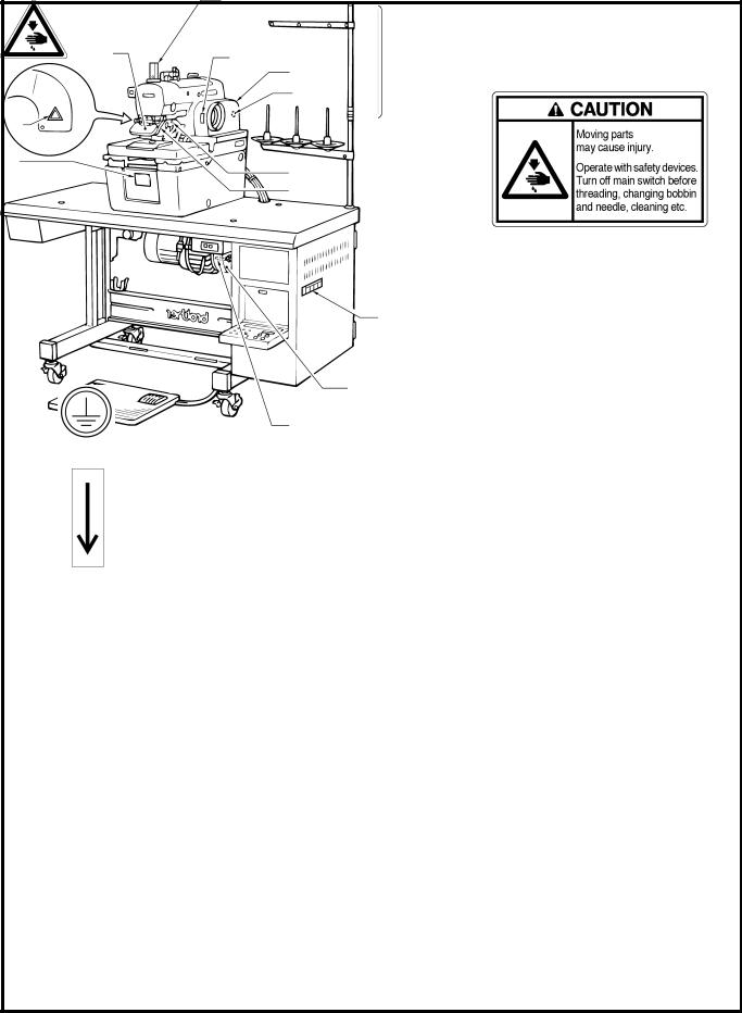
ELECTRONIC EYELET BUTTON HOLER

Thank you very much for buying a BROTHER sewing machine. Before using your new machine, please read the safety instructions below and the explanations given in the instruction manual.
With industrial sewing machines, it is normal to carry out work while positioned directly in front of moving parts such as the needle and thread take-up lever, and consequently there is always a danger of injury that can be caused by these parts. Follow the instructions from training personnel and instructors regarding safe and correct operation before operating the machine so that you will know how to use it correctly.
SAFETY INSTRUCTIONS
1. Safety indications and their meanings
This instruction manual and the indications and symbols that are used on the machine itself are provided in order to ensure safe operation of this machine and to prevent accidents and injury to yourself or other people.
The meanings of these indications and symbols are given below.
Indications
DANGER The instructions which follow this term indicate situations where failure to follow the instructions will almost certainly result in death or severe injury.
The instructions which follow this term indicate situations where failure to follow the CAUTION instructions could cause injury when using the machine or physical damage to
equipment and surroundings.
Symbols
........................................This symbol (  ) indicates something that you should be careful of. The picture inside the triangle indicates the nature of the caution that must be taken.
(For example, the symbol at left means “beware of injury”.)
........................................This symbol ( |
) indicates something that you must not do. |
........................................This symbol ( |
) indicates something that you must do. The picture |
inside the circle indicates the nature of the thing that must be done.
(For example, the symbol at left means “you must make the ground connection”.)
RH-9800
i

2. Notes on safety
 DANGER
Wait at least 5 minutes after turning off the power switch and disconnecting the power cord from the wall outlet before opening the face plate of the control box. Touching areas where high voltages are present can result in severe injury.
 CAUTION
Environmental requirements
Use the sewing machine in an area which is free from sources of strong electrical noise such as high-frequency welders.
Sources of strong electrical noise may cause problems with correct operation.
Any fluctuations in the power supply voltage should be within  10% of the rated voltage for the machine.
Voltage fluctuations which are greater than this may cause problems with correct operation.
The power supply capacity should be greater than the requirements for the sewing machine’s electrical consumption.
Insufficient power supply capacity may cause problems with correct operation.
The pneumatic delivery capability should be greater than the requirements for the sewing machine's total air consumption.
Insufficient pneumatic delivery capability may cause problems with correct operation.
The ambient temperature should be within the range of 5 to 35 during use.
Temperatures which are lower or higher than this may cause problems with correct operation.
The relative humidity should be within the range of 45% to 85% during use, and no dew formation should occur in any devices.
Excessively dry or humid environments and dew formation may cause problems with correct operation.
Avoid exposure to direct sunlight during use. Exposure to direct sunlight may cause problems with correct operation.
In the event of an electrical storm, turn off the power and disconnect the power cord from the wall outlet.
Lightning may cause problems with correct operation.
Installation
Machine installation should only be carried out by a qualified technician.
Contact your Brother dealer or a qualified electrician for any electrical work that may need to be done.
The sewing machine weighs more than 87 kg. The installation should be carried out by two or more people.
Do not connect the power cord until installation is complete, otherwise the machine may operate if the start switch is pressed by mistake, which could result in injury.
Be sure to connect the ground. If the ground connection is not secure, you run a high risk of receiving a serious electric shock, and problems with correct operation may also occur.
All cords should be secured at least 25 mm away from any moving parts. Furthermore, do not excessively bend the cords or secure them too firmly with staples, otherwise there is the danger that fire or electric shocks could occur.
Install the belt covers to the machine head and motor.
If using a work table which has casters, the casters should be secured in such a way so that they cannot move.
Be sure to wear protective goggles and gloves when handling the lubricating oil and grease, so that they do not get into your eyes or onto your skin, otherwise inflammation can result.
Furthermore, do not drink the oil or eat the grease under any circumstances, as they can cause vomiting and diarrhoea.
Keep the oil out of the reach of children.
RH-9800
ii

 CAUTION
Sewing
This sewing machine should only be used by |
If using a work table which has casters, the casters |
|
operators who have received the necessary |
should be secured in such a way so that they |
|
training in safe use beforehand. |
cannot move. |
|
The sewing machine should not be used for any |
Attach all safety devices before using the sewing |
|
applications other than sewing. |
machine. If the machine is used without these |
|
Be sure to wear protective goggles when using the |
devices attached, injury may result. |
|
Do not touch any of the moving parts or press any |
||
machine. |
objects against the machine while sewing, as this |
|
If goggles are not worn, there is the danger that if a |
may result in personal injury or damage to the |
|
needle breaks, parts of the broken needle may |
machine. |
|
enter your eyes and injury may result. |
If an error occurs in machine operation, or if abnormal |
|
Turn off the power switch at the following times, |
||
noises or smells are noticed, immediately turn off the |
||
otherwise the machine may operate if the start |
power switch. Then contact your nearest Brother |
|
switch is pressed by mistake, which could result in |
dealer or a qualified technician. |
|
injury. |
If the machine develops a problem, contact your |
|
When threading the needle |
||
When replacing the needle |
nearest Brother dealer or a qualified technician. |
|
When not using the machine and when leaving |
|
|
the machine unattended |
|
Cleaning
Turn off the power switch before carrying out |
Be sure to wear protective goggles and gloves |
cleaning, otherwise the machine may operate if |
when handling the lubricating oil and grease, so |
the start switch is pressed by mistake, which could |
that they do not get into your eyes or onto your |
result in injury. |
skin, otherwise inflammation can result. |
|
Furthermore, do not drink the oil or eat the grease |
|
under any circumstances, as they can cause |
|
vomiting and diarrhoea. |
|
Keep the oil out of the reach of children. |
Maintenance and inspection
Maintenance and inspection of the sewing |
If the power switch and air need to be left on when |
|
machine should only be carried out by a qualified |
carrying out some adjustment, be extremely |
|
technician. |
careful to observe all safety precautions. |
|
Ask your Brother dealer or a qualified electrician to |
Use only the proper replacement parts as |
|
carry out any maintenance and inspection of the |
specified by Brother. |
|
electrical system. |
If any safety devices have been removed, be |
|
|
||
Turn off the power switch and disconnect the |
absolutely sure to re-install them to their original |
|
power cord from the wall outlet at the following |
positions and check that they operate correctly |
|
times, otherwise the machine may operate if the |
before using the machine. |
|
start switch is pressed by mistake, which could |
Any problems in machine operation which result |
|
result in injury. |
||
from unauthorized modifications to the machine |
||
When carrying out inspection, adjustment and |
||
will not be covered by the warranty. |
||
maintenance |
||
|
||
When replacing consumable parts such as the |
|
|
loopers and knife |
|
|
Disconnect the air hoses from the air supply and |
|
|
wait for the needle on the pressure gauge to drop |
|
|
to “0” before carrying out inspection, adjustment |
|
|
and repair of any parts which use the pneumatic |
|
|
equipment. |
|
RH-9800
iii
3. Warning labels
The following warning labels appear on the sewing machine.
Please follow the instructions on the labels at all times when using the machine. If the labels have been removed or are difficult to read, please contact your nearest Brother dealer.
1 |
2 |
3 |
Do not touch the knife or press any objects |
|
|
|
against the machine while sewing, as this |
|
may result in personal injury or damage to |
|
the machine. |
Safety devices Eye guard Finger guard
Needle bar guard Belt cover, etc.
4
Be sure to connect the ground. If the ground connection is not secure, you run a high risk of receiving a serious electric shock, and problems with correct operation may also occur.
5
Direction of operation |
|
|
|
|
|
|
Needle bar guard |
||||
Eye guard |
5 |
|
|
|
|
Belt cover |
|
||||
|
|
||||
|
|
|
|||
|
|
|
|
|
|
|
|
|
4 (Rear) |
||
3 |
|
|
|
|
|
2 |
3 |
|
|
||
|
|
|
|||
|
|
|
|
|
|
|
|
|
Finger |
||
|
|
|
guard |
|
|
1
Belt cover
Winding prevention bar
2010Q
RH-9800
iv

CONTENTS
1. NAMES OF EACH PART ............................ |
1 |
|
2. SPECIFICATIONS .......................................... |
2 |
|
2-1. Specifications ....................................................... |
2 |
|
3. INSTALLATION................................................. |
3 |
|
3-1. |
Table processing diagram ................................. |
3 |
3-2. |
Installing the motor ............................................. |
4 |
3-3. Installing the machine head ............................... |
4 |
|
3-4. Installing the oil container ................................... |
5 |
|
3-5. Installing the spool stand .................................... |
6 |
|
3-6. |
Tightening the V-belt .......................................... |
6 |
3-7. Installing the control box .................................... |
7 |
|
3-8. Installing the air unit and the valve assembly ....... |
7 |
|
3-9. Connecting the ground wires and the wirings ....... |
8 |
|
3-10.Connecting the air tubes .................................... |
9 |
|
3-11.Installing the air hoses ...................................... |
10 |
|
3-12.Connecting the power cord .............................. |
11 |
|
4. LUBRICATION.................................................. |
12 |
|
4-1. |
Adding oil .......................................................... |
12 |
4-2. |
Lubrication ........................................................ |
12 |
5. CORRECT USE .............................................. |
14 |
|
5-1. |
Initializing settings ............................................. |
14 |
5-2. Changing the lower thread and gimp trimming ........ |
14 |
|
5-3. Checking the direction of machine operation....... |
15 |
|
5-4. |
Installing the needle .......................................... |
16 |
5-5. Threading the upper thread .............................. |
16 |
|
5-6. Threading the lower thread............................... |
17 |
|
5-7. |
Threading the gimp .......................................... |
18 |
5-8. |
Setting the material ........................................... |
18 |
6. USING THE OPERATION PANEL |
|
|
AND FRONT PANEL ................................... |
19 |
|
6-1. Panel button and switch names ...................... |
19 |
|
6-2. Selecting a program number ........................... |
20 |
|
6-3. |
Changing the mode .......................................... |
20 |
6-4. Changing the cutting timing ............................. |
20 |
|
6-5. |
Setting a program ............................................. |
21 |
A. Setting the sewing speed ............................... |
22 |
|
B. Setting the shape of the eyelet....................... |
22 |
|
C. Setting the buttonhole length ......................... |
22 |
|
D. Setting the tacking length ............................... |
23 |
|
E. Setting the offset ............................................. |
23 |
|
F. Setting the stitch pitch..................................... |
23 |
|
G. Setting the number of eyelet stitches............. |
24 |
|
H. Setting the cutting space ................................ |
24 |
|
I. Setting the knife position compensation........ |
24 |
|
P1. Setting X correction....................................... |
25 |
|
P2. Setting Y correction ....................................... |
25 |
|
P3. Setting θ 1 correction....................................... |
25 |
|
P4. Setting θ 2 correction....................................... |
26 |
|
6-6. |
Using the memory switch ................................. |
27 |
6-7. |
List of error codes ............................................. |
29 |
7. SEWING .............................................................. |
30 |
|
7-1. Using the EMERGENCY STOP switch .......... |
30 |
|
7-2. |
Sewing .............................................................. |
31 |
7-3. Adjusting the thread tension ............................ |
32 |
|
7-4. Needle and knife position ................................ |
33 |
|
7-5. Using the production counter .......................... |
35 |
|
7-6. Using a cycle program ..................................... |
36 |
|
7-7. Setting the feed bracket to the front position ...... |
37 |
|
7-8. Switching between single-pedal and dual-pedal |
|
|
|
operation (Switching the foot controller) ............. |
37 |
7-9. |
Using feed mode ............................................. |
38 |
7-10.Using manual mode ........................................ |
39 |
|
7-11.Changing the cycle program counter ............. |
40 |
|
7-12.Setting the number of home position cycles ...... |
40 |
|
7-13.Returning to the home position ....................... |
41 |
|
8. CLEANING AND MAINTENANCE ...... |
42 |
|
8-1. |
Cleaning ........................................................... |
42 |
8-2. |
Draining the oil ................................................. |
42 |
8-3. Checking the air filter ....................................... |
42 |
|
9. STANDARD ADJUSTMENTS ............... |
43 |
|
9-1. Adjusting the height of the spreader and looper....... |
43 |
|
9-2. Adjusting the needle and looper timing ........... |
44 |
|
9-3. Adjusting the loop stroke.................................. |
45 |
|
9-4. Adjusting the height of the needle bar............. |
46 |
|
9-5. Adjusting the clearance between the |
|
|
|
looper and needle............................................. |
46 |
9-6. Adjusting the needle guard .............................. |
47 |
|
9-7. Adjusting the spreader mounting positions......... |
47 |
|
9-8. Adjusting the spreader timing .......................... |
48 |
|
9-9. Adjusting the needle racking width |
|
|
|
(stitch width) ...................................................... |
48 |
9-10.Changing the knife cutting length |
|
|
|
(Replacing the cutting block)............................ |
49 |
9-11.Adjusting the contact between the knife |
|
|
|
and the cutting block ........................................ |
50 |
9-12.Replacing the knife .......................................... |
51 |
|
9-13.Adjusting the cutting pressure ......................... |
51 |
|
9-14.Adjusting the cloth opening amount ............... |
52 |
|
9-15.Adjusting the trimming of the upper thread ...... |
53 |
|
9-16. Adjusting the trimming of the lower thread |
|
|
|
and gimp .......................................................... |
53 |
9-17.Adjusting the gimp length after trimming (-02) ... |
54 |
|
9-18.Lower thread presser (-02) .............................. |
55 |
|
9-19.Sub presser (-02) ............................................. |
55 |
|
10.SUMMARY OF DIP SWITCHES ......... |
56 |
|
10-1. Front panel DIP switches .............................. |
56 |
|
10-2. Circuit board DIP switches ............................ |
57 |
|
11. TROUBLESHOOTING ............................ |
58 |
|

1. NAMES OF EACH PART
1. NAMES OF EACH PART
1096Q
(2) |
(3) |
(1)
(11)
(10)
(4)
(5)
(6)
(9)
(8) |
(7) |
(1) |
Front cover |
(2) |
EMERGENCY STOP switch |
(3) |
Upper shaft pulley |
(4) |
Control panel |
(5) |
Control box |
(6) |
Front panel |
(7) |
Start switch |
(8) |
Cloth presser switch |
(9) |
Foot controller |
(10) Power switch |
(11) |
Motor |
|
|
|
RH-9800
1

2. SPECIFICATIONS
2. SPECIFICATIONS
2-1. Specifications
DH4-B980- RH-9800-

Upper thread |
Lower thread trimmer |
|
trimmer |
Long type |
Short type |
-00 |
- |
- |
-01 |
|
- |
-02 |
- |
* |
*-02 is further divided into L1 - L7 specifications in accordance with the stitch length. Please be sure to specify the stitch length when ordering.
Specification |
|
-00 |
|
-01 |
|
|
|
-02 |
||
Application |
|
Men's clothes and ladies' clothes |
|
|
Jeans and work clothes |
|||||
Sewing speed |
|
|
1,000 - 2,000 rpm (100 rpm steps) |
|
|
|||||
|
|
|
|
|
|
|
|
L1 14 – 18 mm |
L5 28 – 32 mm |
|
Button hole length |
|
10 – 50 mm |
|
10 – 38 mm |
|
L2 18 – 22 mm |
L6 32 – 36 mm |
|||
|
|
|
L3 22 – 26 mm |
L7 36 – 40 mm |
||||||
|
|
|
|
|
|
|
|
|||
|
|
|
|
|
|
|
|
L4 26 – 30 mm |
|
|
Stitch pitch |
|
|
|
0.5 - 2.0 mm (0.1 mm steps) |
|
|
|
|||
Stitch width |
|
|
|
1.5 - 3.2 mm |
|
|
|
|||
Tacking length |
|
|
|
3 – 43 mm (1 mm steps) or none |
|
|
|
|||
Cloth presser height |
|
|
12 mm |
|
|
|
16 mm |
|||
Stitch shape |
|
|
|
Selected by a program |
|
|
|
|||
changing |
|
|
|
|
|
|
||||
|
|
|
|
|
|
|
|
|
|
|
Cut timing selection |
|
|
|
Selected by a switch |
|
|
|
|||
Starting method |
|
Dual switch (cloth presser switch and start switch) or single switch |
|
|||||||
Feed method |
|
|
Intermittent feed by three pulse motors (X, Y, θ ) |
|
|
|||||
Needle |
|
|
DO x 558 Nm 80 – Nm 120 (Schmetz) |
|
|
|||||
Safety equipment |
Built-in emergency stop function and automatic stopping device which stops the machine when |
|||||||||
|
|
|
the safety circuit is activated |
|
|
|
||||
|
|
|
|
|
|
|
||||
Air pressure |
|
|
|
Main regulator: 0.5 MPa |
|
|
|
|||
|
|
Knife pressure regulator: 0.3 MPa |
|
|
|
|||||
|
|
|
|
|
|
|||||
Air consumption |
|
|
|
43.2 l/min. (8 cycles/min.) |
|
|
|
|||
Noise level |
|
81 dB at max. speed of 2,000 rpm, measured according to ISO 10821 |
||||||||
Dimensions |
|
|
1,200 mm (W) x 590 mm (D) x 1,120 mm (H) |
|
|
|||||
Work table legs |
|
|
|
T-shaped height-adjustable type |
|
|
|
|||
|
|
|
Single-phase 110, 200, 220, 230, 240 V |
|
|
|||||
Power supply |
|
|
|
3-phase 220, 380, 415 V |
|
|
|
|||
|
|
|
Maximum electric power consumption: 1 kVA |
|
|
|||||
Weight |
|
|
|
175 kg |
|
|
|
|||
|
|
|
|
|
||||||
|
|
Eyelet buttonhole |
|
Straight buttonhole |
||||||
Sewing shape |
|
|
|
|
|
|
|
|
|
|
|
0793Q |
|
0794Q |
|
0795Q |
|
0796Q |
|
||
|
Eyelet buttonhole |
Eyelet buttonhole with |
|
Straight buttonhole |
Straight buttonhole |
|||||
|
|
taper |
|
with taper |
||||||
|
|
|
|
|
|
|
|
|||
RH-9800
2
3.INSTALLATION
3. INSTALLATION
 CAUTION
Machine installation should only be carried out by |
All cords should be secured at least 25 mm away |
|
a qualified technician. |
from any moving parts. Furthermore, do not |
|
Contact your Brother dealer or a qualified electrician |
excessively bend the cords or secure them too |
|
firmly staples, otherwise there is the danger that |
||
for any electrical work that may need to be done. |
||
fire or electric shocks could occur. |
||
The sewing machine weighs more than 87 kg. The |
||
Be sure to connect the ground. If the ground |
||
installation should be carried out by two or more |
||
connection is not secure, you run a high risk of |
||
people. |
||
receiving a serious electric shock, and problems |
||
Do not connect the power cord until installation is |
||
with correct operation may also occur. |
||
complete, otherwise the machine may operate if |
Install the belt covers to the machine head and |
|
the start switch is pressed by mistake, which could |
||
motor. |
||
result in injury. |
||
|
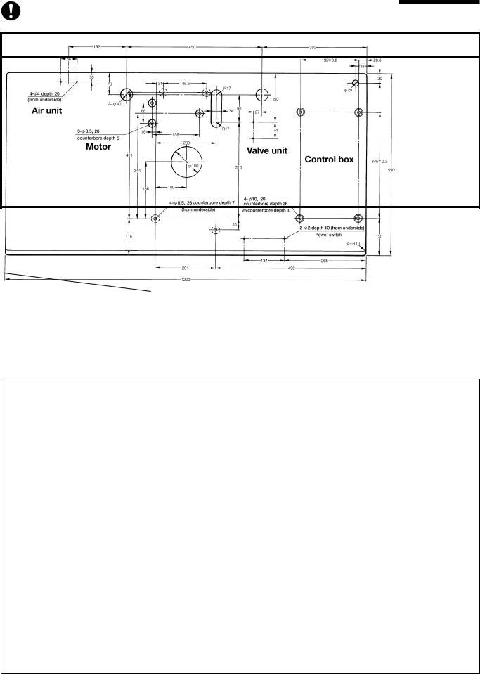
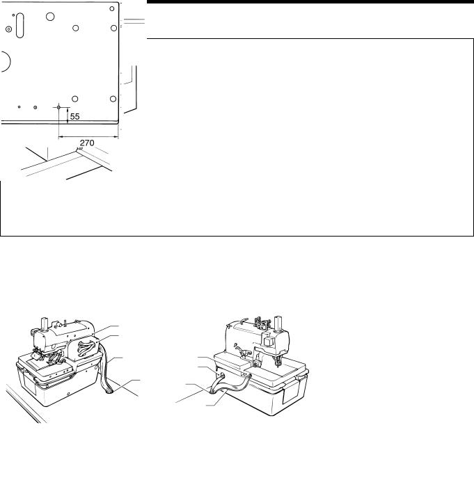
3-1. Table processing diagram
Use the special table indicated below.
Thread trimmer |
Product code |
|
|
Upper thread trimmer |
127-980-000-01 |
Upper and lower thread trimmer |
127-980-001-01 |
|
|
If using a commercially-available table, process it as shown in the illustration below.
Note: The thickness of the table should be at least 50 mm, and it should b e strong enough to bear the weight and vibration of the sewing machine.
2011Q
RH-9800
3
3. INSTALLATION
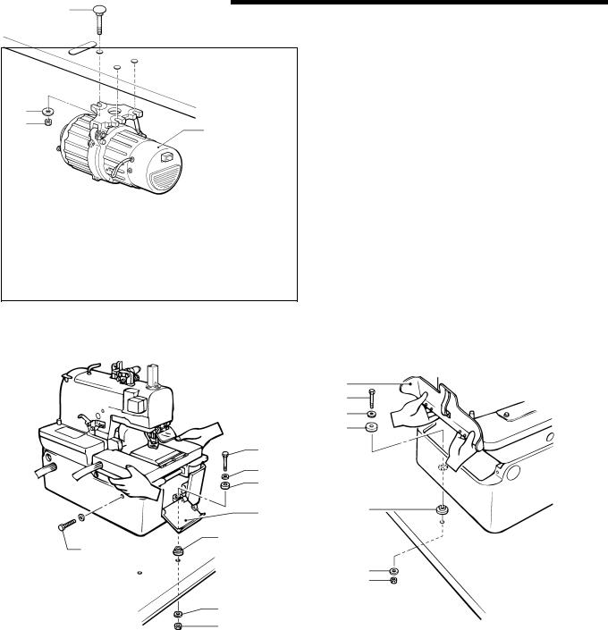
3-2. Installing the motor
(1)
(3) |
|
(4) |
(2) |
|
1.Insert the three bolts (1) into the work table.
2.Turn the work table upside down to make it easier to install the motor (2).
3.Align the motor (2) with the bolts (1), and then install the motor (2) to the underside of the work table with the three washers (3) and the three nuts (4).
Note: Do not use the cushion rubber. If you use it, V belt tension cannot be adjusted.
1098Q
3-3. Installing the machine head
|
(8) |
|
(3) |
|
(4) |
|
(5) |
(3) |
|
(4) |
|
(5) |
|
(2) |
(1) |
(1) |
|
(9) |
|
|
(6) |
|
(7) |
(6) |
|
(7) |
|
1099Q |
0808Q |
|
|
1.Insert the accessory bed stand cushions A (1) into the bed stand, and then place the machine head on top of the work table.
Note: When placing the machine head on top of the work table, have two or more people there to hold the handles A and B and the rear of the head C.
2.Open the front cover (2), and then use the bed stand mounting bolt (3), washer (4), cushioning rubber (5), bed stand cushion A (1), large washer (6) and nut (7) to attach the front right corner of the bed stand to the work table.
3.Open the rear cover (8), and then attach the bed stand to the work table in two places inside the stand in the same way as in step 2. above.
4.Remove the fixing bolt (9) and the washer.
Note: The fixing bolt (9) and washer should be kept, as they will be needed again if the machine head is moved.
5.Raise the machine head, and then attach the front left corner of the bed stand to the work table in the same way as in
the steps above.
Note: Make sure that steps 2. to 4. above have been completed before raising the machine head.
RH-9800
4
3.INSTALLATION
Raising the machine head
|
(2) |
|
|
|||
(1) |
(3) |
|
|
|
||
(4) |
|
|
|
|
|
|
(5) |
|
|
|
|
When machine |
|
|
|
|
|
|
||
|
|
(3) |
|
head is lowered |
||
|
|
|
|
|
|
|
(1) |
|
|
(2) |
|
|
|
When machine head is raised |
|
|||||
0809Q |
0810Q |
|||||
|
|
|
|
|
|
|
1.While holding the handles of the machine head (1) with both hands, gently raise the machine head. Note: Be sure to turn the power supply off before raising the machine head.
2.If you wish to keep the machine head in the raised position, insert the head support lever (2) securely into the hinge lever support shaft (3).
Note: Always check that the head support lever (2) and the hinge lever support shaft (3) are meshed.
Lowering the machine head
Pull the machine head down toward you gently, remove the head support lever (2) from the hinge lever support shaft
(3), and then gently lower the machine head.
Note: Do not hold the machine head by the feed bracket (4) or X feed shaft A (5) when it is being raised and lowered.
3-4. Installing the oil container
0811Q
|
(5) |
|
|
|
(1) |
(1) |
|
(2) |
(5) |
(3) |
(3) |
|
|
(4) |
0812Q
1.Install the oil draining cap support (2) to the base of the bed stand (1) with the two screws (3).
2.Screw the oil container (4) into the oil draining cap support (2).
3.Push the oil draining spring pin (5) into the bed stand
(1) until the pin is flush with the surface of the stand.
4.Lower the machine head. (Refer to "Lowering the machine head" above.)
RH-9800
5
3. INSTALLATION
3-5. Installing the spool stand
1. To assemble the spool stand (1), follow the instructions in the manual that came with the spool stand (1).
2. Secure the spool stand (1) to the rear right corner of the work table with the washer and nut (2).
(1)
(2)
0815Q
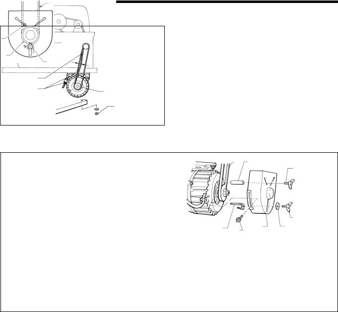
3-6. Tightening the V-belt
(1) |
(9) |
1198Q |
|
(10) |
|||
|
|
|
|
|
|
|
|
(6) |
|
|
Approx. |
(8) |
(2) |
(3) |
(7) |
|
0.1N |
|
|
|||
|
10 mm |
|
|
|
(1) |
|
|
|
|
|
|
||
(1) |
|
|
|
|
|
|
(5) |
|
(4) |
(9) |
|
|
|
|
|
|
|
|
||
|
|
|
|
|
|
|
|
|
|
Motor pulley |
|
|
(7) |
|
|
|
|
|
|
|
1100Q |
|
|
|
|
|
1101Q |
1.Open the rear cover.
2.Pass the V-belt (1) through the base of the bed stand and through the hole in the work table.
3.Loosen the two screws (2) and then remove the motor pulley cover (3).
4.Place the V-belt (1) onto the motor pulley (4).
5.Check that there is approximately 10 mm of deflection in the V-belt (1) when it is pushed in the middle with a load of 0.1 N. If the tightness needs adjusting, loosen the two nuts (5) and move the motor up or down.
6.Install the belt casting prevention bracket (8) to the pulley cover (3) with the wing bolt (6) and washer (7). Align the center of the washer (7) with the gradation (7) 0 shown on the outside of the pulley at this time.
7.Provisionally tighten the winding prevention bar (9) to the pulley cover (3) with the wing bolt (10).
8.Install the pulley cover (3) and tighten it with the two screws (2).
Note: Check that the V-belt is not touching the belt casting prevention bracket (8).
9.Align the winding prevention bar (9) with the point in between the V-belt and the motor pulley, and then secure it by tightening the wing bolt (10).
Note: Check that the winding prevention bar (9) does not touching the V-belt or the motor pulley.
 After a long period of use, the V-belt will become run in and will loosen around the motor pulley. When this happens, turn off the power and adjust by the procedure given in step 5. above.
RH-9800
6
3.INSTALLATION
3-7. Installing the control box
(5)
(2)
(3)
(4)
(1)
1102Q
1.Align the four bolt holes in the control box (1) with the four holes in the work table.
2.Install the control box (1) with the four bolts (2), spring washers (3) and flat washers (4)
3.Push the four caps (5) in over the top of the bolts (2).
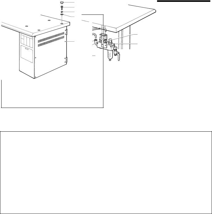
3-8. Installing the air unit and the valve assembly
Refer to the work table processing diagram on page 3 for the installation position.
(6)
(3)
12-pin connector |
(8) |
(4) |
|
||
|
|
(5) |
|||
|
|
|
|||
|
|
|
|
|
|
|
|
|
(7) |
|
(1) |
|
|
|
|
|
|
|
|
|
|
|
|
No.6 (black) |
Black cable |
No. 15 |
|
(2) |
|
No.4 (black) |
|
|
|
||
No. 16 |
|
||||
|
|
|
|||
Black cable
12-pin connector
1103Q
1.Install the air unit (1) to the underside of the work table with the two screws (2).
2.Install the valve assembly (3) with the two screws (4).
3.Connect air hose No. 15 to the intermediate joint (5) of the air unit (1) and to the joint (6) of the valve assembly (3), and connect air hose No. 16 to joints (7) and (8).
Connecting the knife valve cables
Connect the two black knife valve cables to terminal No.4 and No.6 of the 12-pin connector of the air harness.
RH-9800
7
3. INSTALLATION
3-9. Connecting the ground wires and the wirings
1106Q
|
(2) |
|
(7) |
|
|
|
|
|
|
|
|
||
|
(1) |
|
(3) |
|
|
|
|
|
(4) |
|
|
|
|
|
|
|
(6) |
|
|
|
|
|
|
(5) |
|
|
|
|
|
|
|
|
|
|
|
|
|
|
|
|
|
|
|
|
1105Q |
Power switch installation position |
||
1104Q |
|
|||||
|
|
|
|
|||
1.Connect the foot controller cable (1) and the motor cable (2) to the control box.
2.Install the power switch (3) to the underside of the work table with the two screws (4).
3.Clamp the foot controller cable (1) with the two cable clips (5) and then secure the cable clips (5) with the screws (6).
4.Install the motor cable (2) and the power switch cable to the underside of the work table with the staple (7).
1107Q |
|
(12) |
1109Q |
(16) |
|
|
|
|
|
|
|
|
|
(11) |
|
|
|
|
|
(16) |
(8) |
|
(17) |
|
|
|
Needle |
||
|
|
|
(9) |
|
|
|
|
(13) |
White |
position sensor |
|
|
|
|
|||
|
|
(10) |
Blue |
6P |
|
|
|
|
Black |
||
|
|
|
|
6P |
|
|
|
|
(17) |
White |
6P |
|
|
|
|
White |
12P |
|
|
|
|
White |
(18) |
|
|
|
|
(19) |
4P |
|
(15) |
(14)(10) |
|
|
|
1108Q |
(15) |
|
1110Q |
1111Q |
|
|
|
||||
|
|
|
|
|
|
5.Pass the cable and air tube which are coming out of the feed bracket (8) and the left side of the bed stand (9) through the cable hole (10) in the work table.
6.Pass the cable and air tube which are coming out of the belt cover (11) and the machine head (12) through the cable hole (13) in the work table.
7.Insert each of the connectors into the connectors on the control box. (Refer to the illustration above.)
8.Pass the cables and air hoses through the two cable holders (14), and then secure the cable holders (14) to the underside of the work table with the two screws (15).
9.The ground wires (16), (17) should always be connected to the control box.
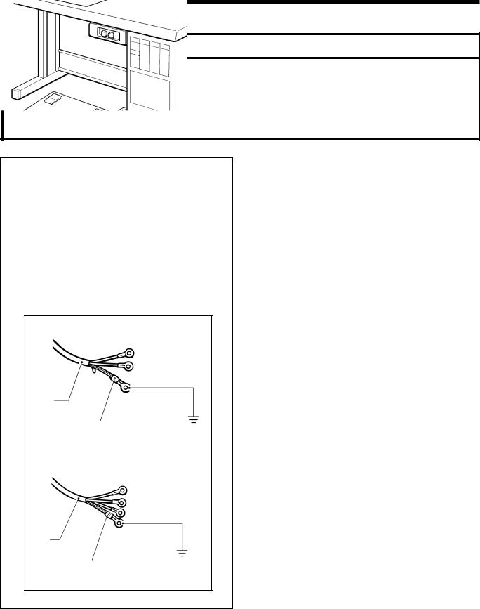
10.Connect the accessory ground wire (18) to the ground terminal of the control box and to the table leg installation bolt. Note: If the ground wire is not connected, mis-operation due to discharges of static electricity may occur.
11.Connect the power switch connector (19) to the motor.
RH-9800
8
|
|
|
|
|
|
|
|
3.INSTALLATION |
|
|
|
|
|
|
|
|
|
|
|
|
|
|
|
|
|
|
|
|
|
|
|
|
|
|
|
|
|
|
|
< -02 > |
|
|
|
|
|
|
|
|
|
|
|
|
|
|
|
|
|
|
|
|
|
|
|
|
|
|
|
|
|
|
(6) |
|
|
|
|
|
Label No. of |
Right/left cloth presser No. |
|
|
|
|
|
|
|
Specification |
harness |
Right/left movable knife No. |
|
|
|
|
|
|
|
Thread handler No. |
|
||
|
(4) |
|
|
|
|
|
|
|
|
|
No. |
|
|
|
L1 |
1 |
1 |
|
|
|
|
|
|
|
|
||||
|
|
No. |
|
|
|
|
|
|
|
(7) |
|
|
|
(5) |
L2 |
2 |
2 |
|
|
|
|
|
|
|
|||||
No.10 |
|
|
(2) |
|
L3 |
3 |
3 |
|
|
|
|
|
|
|
|||||
(1) |
|
|
|
|
L4 |
4 |
4 |
|
|
|
|
(3) |
|
|
|
||||
Label No. |
|
|
|
|
|
L5 |
5 |
5 |
|
|
|
|
|
|
|
|
|
|
|
|
|
|
|
|
|
L6 |
6 |
6 |
|
|
|
|
|
|
|
|
|
|
|
|
|
|
|
|
|
L7 |
7 |
7 |
|
|
|
|
|
|
|
|
|
||
1112Q |
|
|
1113Q |
|
|
|
|||
|
|
|
|
|
|
|
|
|
|
 Insert the harness (L1 - L7) (1) to connector No. 10 (9-pin).
*When connecting the harness (1), check that its label number is the same as the numbers on the right movable knife (2), left movable knife (3), thread handler (4), right cloth presser (5), left cloth presser (6) and movable knife driving cam (7). (If a connector with a different label number is inserted, the machine could be damaged or thread trimming errors could result.)
*There is 10 mm of difference in the knife installation positions between L1 - L4 and L5 - L7.
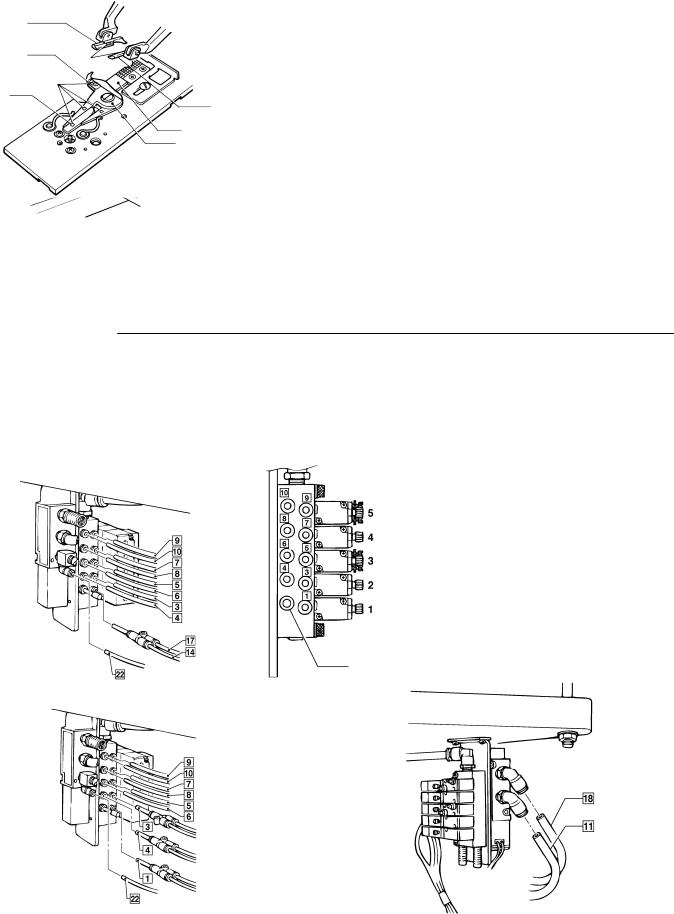
3-10. Connecting the air tubes
Connect the air tubes to the joints of the solenoid valve assembly, using the illustration below as a reference. Numbers are marked on each of the air hoses which come out of the sewing machine.
< -00,-01 > |
0827Q |
|
|
|
|
|
Label No. |
Solenoid valve |
|
||
|
|
|
|||
|
|
|
5 |
Upper thread trimming |
|
|
|
|
4 |
Upper thread tightening |
|
|
|
|
3 |
Lower thread trimming *1 |
|
|
|
|
2 |
Cloth spreading |
|
|
|
|
(Sub presser *2) |
|
|
|
|
|
|
|
|
|
|
|
1 |
Cloth presser |
|
|
*1 |
If the lower thread trimmer is not |
|||
|
|
|
installed, solenoid valve [3] is not |
||
|
|
|
used. |
|
|
|
*2 |
The sub presser can only be used |
|||
|
Plug 4 |
for machines with -02 specification. |
|||
0826Q |
|
|
|
||
< -02 > |
|
|
|
|
|
0828Q |
|
|
|
0829Q |
|
|
|
|
|
|
|
RH-9800
9
3. INSTALLATION
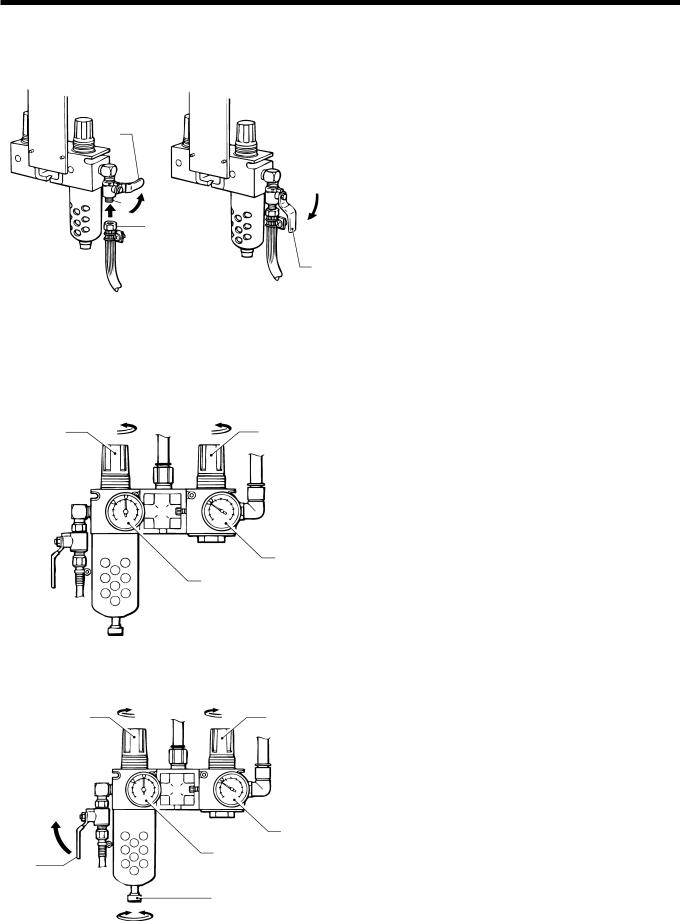
3-11. Installing the air hoses
Connect the air hose from the compressor to the air unit underneath the work table.
|
|
1. |
Turn the nut (1) at the end of the air hose, and then |
|
|
||
|
|
|
connect the hose to the valve (2). |
|
|
2. |
Open the air cock (3) on the compressor. |
(3) |
|
|
Check that there is no air leaking from the valve |
|
|
|
connection. |
|
|
3. |
Open the cock (3) by turning it in the direction of the |
|
Open |
|
arrow. |
(2) Closed |
|
|
The meter needle will move clockwise. |
(1) |
|
4. |
Adjust the air pressure by following the procedure on |
|
|
the next page. |
|
|
|
|
|
|
(3) |
|
|
0834Q |
0835Q |
|
|
|
|
|
|
Adjusting the air pressure
Set the air pressure for the knife pressure adjustment regulator (3) to the lowest pressure at which the knife can still cut
the material. Set the standard air pressure for the main regulator (1) to 0.5 MPa.
To increase the air pressure
(2) |
|
(4) |
|
|
(3) |
|
(1) |
(0.3 MPa) |
|
|
|
|
(0.5 MPa) |
|
|
|
0836Q |
|
|
|
To decrease the air pressure |
|
|
|
|
|
(2) |
|
(4) |
To close |
|
(3) |
|
|
|
(5) |
(1) |
(0.3 MPa) |
(0.5 MPa) |
|
|
|
(6) |
|
To loosen |
To tighten |
|
|
|
0837Q |
|
|
|
1.Gently lift the knob (2) of the main regulator (1) and turn it in the direction of the arrow in the illustration. The pressure will increase when the knob (2) is turned clockwise.
2.Gently lift the knob (4) of the knife pressure adjustment regulator (3) and turn it in the direction of the arrow in the illustration.
The pressure will increase when the knob (4) is turned clockwise.
*The pressure for the knife pressure adjustment regulator (3) is adjusted to 0.3 MPa. Be careful not to increase this pressure needlessly, otherwise poor cutting performance or damage to the knife may result.
1.Close the cock (5). (The needle will remain at the high pressure position.)
2.Turn the knob screw (6) in the direction of the arrow in the illustration to loosen it. Make sure that you turn it in the correct direction.
The air will escape from the reservoir and the needle will drop.
3.Tighten the knob screw (6).
4.To reduce the air pressure, gently lift knob (2) or knob
(4) and turn it counterclockwise.
5.Open the cock (5). Air will enter the reservoir and the needle will move
RH-9800
10
3.INSTALLATION
3-12. Connecting the power cord
 CAUTION
Contact your Brother dealer or a qualified electrician for any electrical work that may need to be done.
Be sure to connect the ground. If the ground connection is not secure, you run a high risk of receiving a serious electric shock, and problems with correct operation may also occur.
Do not connect the power cord until installation is complete, otherwise the machine may operate if the start switch is pressed by mistake, which could result in injury.
1114Q
Single phase
(1)
Green and yellow wire |
|
(ground wire) |
0839Q |
|
|
|
|
Three phase |
|
(1)
Green and yellow wire |
|
(ground wire) |
0840Q |
|
1.Attach an appropriate plug to the power cord (1). (The green and yellow wire is the ground wire.)
2.Insert the plug into properly-grounded AC power
supply.
Note: Do not use extension cords, otherwise machine operation problems may result.
RH-9800
11
4. LUBRICATION
4. LUBRICATION
 CAUTION
Turn off the power switch before starting lubricating, otherwise the machine may operate if the start switch is pressed by mistake, which could result in injury.
Be sure to wear protective goggles and gloves when handling the lubricating oil and grease, so that they do not get into your eyes or onto your skin, otherwise inflammation can result.
Furthermore, do not drink the oil or eat the grease under any circumstances, as they can cause vomiting and diarrhoea.
Keep the oil out of the reach of children.
Use only specified Brother oil (Nisseki Mitsubishi Sewing Lube 10 N; VG10) for the machine oil.
4-1. Adding oil
Check the oil level by looking at the sight glass. If the oil level is low, replenish the oil supply.
Filling the arm oil tank |
Filling the bed base oil tank |
(1)
(2)
0859Q |
|
0860Q |
||
|
|
|
|
|
1. Pour approximately 10 cc of machine oil into the arm oil |
1. |
Raise the machine head. |
||
tank (1) (until it is about four-fifths full). |
2. |
Pour approximately 20 cc of machine oil into the bed |
||
|
|
|
base oil tank (2) (until it is about four-fifths full). |
|
|
|
3. |
Lower the machine head. |
|
4-2. Lubrication
Oil these parts once a day.
Oil the moving parts of the needle bar, looper and spreader mechanisms and also the cam groove, roller, the felt at the base of the wick and the wick before using the sewing machine for the first time, and also after long periods of non-use. When oiling, some oil will get onto the thread. Carry out a test sewing to ensure that your material does not get stained with oil.
Oiling the needle bar and cam
Add 2-3 drops of oil in the places indicated by the arrows.
0861Q
RH-9800
12

4.LUBRICATION
Oiling the looper, spreader and race stand <Removing the cloth presser plates>
1116Q
(3) |
|
|
|
|
|
|
|
|
(6) |
|
|
|
|
|
(4) |
(6) |
|
|
|
|
|
|
|
(2) |
|
|
(10) |
|
(4) |
|
(A) |
|
|
|
|
|
|
|
|
|
|
|
|
|
|
(8) |
|
|
|
|
|
|
|
|
|
|
|
(5) |
|
(1) |
|
|
(9) |
|
|
|
|
|
(7) |
|
|
0862Q |
|
1117Q |
|||
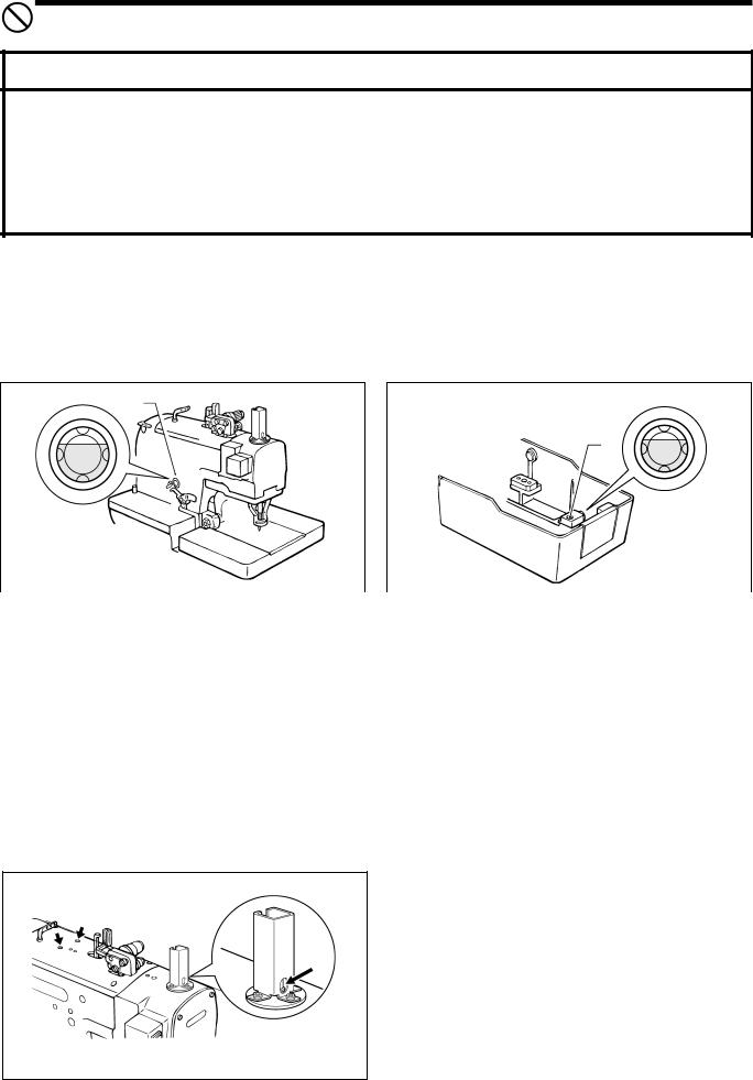
1.Turn the upper shaft pulley (1) toward you until the mark on the pulley (A) is aligned with the notch in the pulley cover (2).
2.Move the feed bracket (3) toward you.
3.Turn the left and right plate pressers (4) in the directions indicated by the arrows.
4.Lift up the clamp lever (6) and the notched section (7) of the right cloth presser plate (5), remove the right cloth presser
plate (5) from the pin (8), and then pull the right cloth presser plate (5) toward you to remove it.
Note: If the lower thread trimmer has been installed, move cloth presser plate U (9) to a position where it can be removed without its touching the needle.
Raise cloth presser plate U (9), pass the needle through the hole, and then remove cloth presser plate U (9) from the pin (8).
5. Remove the left cloth presser plate (10) in the same way as the right cloth presser plate (5) was removed.
0868Q
|
|
|
|
(18) |
|
|
(13) |
(12) |
(17) |
||
|
|||||
|
|
|
|||
|
|
(11) |
(15) |
(14) |
|
|
|
|
|
|
|
|
|
(16) |
|
|
|
1118Q |
0866Q |
|
1119Q |
||
6.Open the front cover.
7.Turn the race stand and add a few drops of oil to the spreader cam (11), and to the supports for the looper link (12) and spreader link (13).
8.Add a few drops of oil to the shafts of the right spreader (14), left spreader (15) and LS-holder bracket (16).
9.Fill the felt tank (17) on the race stand with oil also.
10.Add 5 - 6 drops of oil to the felt (18) which is attached to the sliding surfaces of the race stand and the bed.
11.Close the front cover.
12.Install the cloth presser plates by carrying out the steps 5., 4. and 3. in that order.
RH-9800
13
5. CORRECT USE
5. CORRECT USE
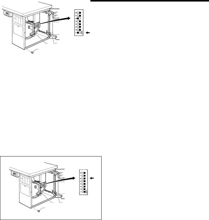
5-1. Initializing settings
The following procedure should be carried out before the sewing machine is used for the first time, and also after long periods of non-use.
If "E-59" appears on the front panel display when the power is turned on, be sure to follow this procedure to initialize all settings. ("E-59" will appear after a PROM has been replaced or after long periods of non-use. For details on the "E-59" message display, refer to page 27.)
|
|
|
1. |
Turn off the power. |
|
|
|
||
|
|
|
2. |
Remove the five screws (1). |
|
|
|
3. |
Open the rear plate (2) of the control box. |
|
|
|
4. |
Set DIP switch No. 1 (3) on the circuit board to ON. |
|
|
|
5. |
Turn the power back on again. |
|
|
|
|
Note: A buzzer will sound while the data is being |
|
|
|
|
initialized. |
|
|
|
6. |
Turn off the power. |
|
(3) (2) |
|
7. |
Set DIP switch No. 1 (3) on the circuit board to OFF. |
|
|
8. |
Close the rear plate (2) and tighten the five screws (1). |
|
|
(1) |
|
|
|
|
|
1120Q |
|
|
|
|
|
|
|
5-2. Changing the lower thread and gimp trimming
The sewing machine is set to lower thread and gimp trimming when it is shipped from the factory. (DIP switch No. 6 (3) is set to ON.)
Carry out the following procedure only if you wish to activate upper thread trimming.
(3)(2)
(1)
1.Turn off the power.
2.Remove the five screws (1).
3.Open the rear plate (2) of the control box.
4.Set DIP switch No. 6 (3) on the circuit board to OFF.
Note: Do not activate lower thread trimming if using a 39-mm cutter.
Do not set DIP switch No. 6 (3) on the circuit board to ON.
5. Close the rear plate (2) and tighten the five screws (1).
1121Q
RH-9800
14
Loading...