


 Loading...
RH-9820
INSTRUCTION MANUAL
Please read this manual before using the machine.
Please keep this manual within easy reach for quick reference.
ELECTRONIC EYELET BUTTON HOLER
Thank you very much for buying a BROTHER sewing machine. Before using your new machine, please read the safety instructions and the explanations given in the instruction manual.
With industrial sewing machines, it is normal to carry out work while positioned directly in front of moving parts such as the needle and thread take-up lever, and consequently there is always a danger of injury that can be caused by these parts. Follow the instructions from training personnel and instructors regarding safe and correct operation before operating the machine so that you will know how to use it correctly.
RH-9820

SAFETY INSTRUCTIONS
[1] Safety indications and their meanings
This instruction manual and the indications and symbols that are used on the machine itself are provided in order to ensure safe operation of this machine and to prevent accidents and injury to yourself or other people.
The meanings of these indications and symbols are given below.
Indications
DANGER |
The instructions which follow this term indicate situations where failure to follow |
the instructions may result in death or serious injury. |
|
|
|
CAUTION |
The instructions which follow this term indicate situations where failure to follow |
the instructions could cause injury when using the machine or physical damage |
|
|
to equipment and surroundings. |
|
|
Symbols |
|
..……… This symbol (  ) indicates something that you should be careful of. The picture inside the triangle indicates the nature of the caution that must be taken.
(For example, the symbol at left means “beware of injury”.)
..………
..………
This symbol (  ) indicates something that you must not do.
This symbol (  ) indicates something that you must do. The picture inside the circle indicates the nature of the thing that must be done.
(For example, the symbol at left means “you must make the ground connection”.)
RH-9820 |
i |

[2] Notes on safety
 DANGER
Wait at least 5 minutes after turning off the power switch and disconnecting the power cord from the wall outlet before opening the cover of the control box. Touching areas where high voltages are present can result in severe injury.
 CAUTION
Environmental requirements
Use the sewing machine in an area which is free from sources of strong electrical noise such as electrical line noise or static electric noise.
Sources of strong electrical noise may cause problems with correct operation.
Any fluctuations in the power supply voltage should be within ±10% of the rated voltage for the machine. Voltage fluctuations which are greater than this may cause problems with correct operation.
The power supply capacity should be greater than the requirements for the sewing machine's power consumption.
Insufficient power supply capacity may cause problems with correct operation.
The pneumatic delivery capability should be greater than the requirements for the sewing machine's total air consumption.
Insufficient pneumatic delivery capability may cause problems with correct operation.
The ambient temperature should be within the range of 5°C to 35°C during use.
Temperatures which are lower or higher than this may cause problems with correct operation.
The relative humidity should be within the range of 45% to 85% during use, and no dew formation should occur in any devices.
Excessively dry or humid environments and dew formation may cause problems with correct operation.
In the event of an electrical storm, turn off the power and disconnect the power cord from the wall outlet. Lightning may cause problems with correct operation.
Installation
Machine installation should only be carried out by a qualified technician.
Contact your Brother dealer or a qualified electrician for any electrical work that may need to be done.
The sewing machine weighs approximately 120 kg. Installation of the sewing machine and adjustment of the table height should be carried out by four or more people.
Do not connect the power cord until installation is complete. If this is not done, the sewing machine may operate if the start switch is pressed by mistake, which could result in serious injury.
Hold the machine head with both hands when tilting it back or returning it to its original position.
In addition, do not subject the machine head to extra force while it is tilted back.
If this is not observed, the machine head may become unbalanced and fall over (together with the table), and serious injury or damage to the sewing machine may result.
Be sure to connect the ground. If the ground connection is not secure, you run a high risk of receiving a serious electric shock, and problems with correct operation may also occur.
All cords should be secured at least 25 mm away from any moving parts. Furthermore, do not excessively bend the cords or secure them too firmly with staples.
If this is not observed, fire or electric shocks may result.
Install belt covers to the machine head.
If using a work table which has casters, the casters should be secured in such a way so that they cannot move.
Be sure to wear protective goggles and gloves when handling the lubricating oil, so that it does not get into your eyes or onto your skin.
If care is not taken, inflammation can result. Furthermore, do not drink the lubricating oil. Diarrhea or vomiting may result.
Keep the oil out of the reach of children.
ii
RH-9820

 CAUTION
Sewing
This sewing machine should only be used by |
If using a work table which has casters, the casters |
|
operators who have received the necessary training |
should be secured in such a way so that they cannot |
|
in safe use beforehand. |
move. |
|
The sewing machine should not be used for any |
Attach all safety devices before using the sewing |
|
applications other than sewing. |
machine. If the machine is used without these |
|
Be sure to wear protective goggles when using the |
devices attached, injury may result. |
|
|
||
machine. |
Do not touch any of the moving parts or press any |
|
If goggles are not worn, there is the danger that if a |
objects against the machine while sewing, as this |
|
needle breaks, parts of the broken needle may enter |
may result in personal injury or damage to the |
|
your eyes and injury may result. |
machine. |
|
Turn off the power switch at the following times. If |
If an error occurs in machine operation, or if |
|
this is not done, the sewing machine may operate if |
abnormal noises or smells are noticed, immediately |
|
the start switch is pressed by mistake, which could |
turn off the power switch. Then contact your nearest |
|
result in serious injury. |
Brother dealer or a qualified technician. |
|
• When threading the needle |
If the machine develops a problem, contact your |
|
• When replacing the needle |
||
nearest Brother dealer or a qualified technician. |
||
• When not using the machine and when leaving the |
|
|
machine unattended |
|
Cleaning
Turn off the power switch before carrying out this |
Be sure to wear protective goggles and gloves when |
operation. If this is not done, the sewing machine |
handling the lubricating oil, so that it does not get into |
may operate if the start switch is pressed by mistake, |
your eyes or onto your skin. |
which could result in serious injury. |
If care is not taken, inflammation can result. |
|
Furthermore, do not drink the lubricating oil. Diarrhea |
|
or vomiting may result. |
|
Keep the oil out of the reach of children. |
Maintenance and inspection
Maintenance and inspection of the sewing machine |
Hold the machine head with both hands when tilting |
||||
should only be carried out by a qualified technician. |
it back or returning it to its original position. |
||||
Ask your Brother dealer or a qualified electrician to |
In addition, do not subject the machine head to extra |
||||
force while it is tilted back. |
|||||
carry out any maintenance and |
inspection of the |
||||
If this is not observed, the machine head may |
|||||
electrical system. |
|
|
|||
|
|
become unbalanced and fall over (together with the |
|||
Turn off the power switch and disconnect the power |
|||||
table), and serious injury or damage to the sewing |
|||||
cord at the following times. If this is not done, the |
machine may result. |
||||
sewing machine may operate if the start switch is |
If the power switch and air need to be left on when |
||||
pressed |
by mistake, |
which could |
result in serious |
||
carrying out some adjustment, be extremely careful |
|||||
injury. |
|
|
|
||
|
|
|
to observe all safety precautions. |
||
• When |
carrying out |
inspection, |
adjustment and |
||
maintenance |
|
|
Use only the proper replacement parts as specified |
||
• When replacing consumable parts such as the |
by Brother. |
||||
loopers and knife |
|
|
If any safety devices have been removed, be |
||
Disconnect the air hoses from the air supply and wait |
absolutely sure to re-install them to their original |
||||
for the needle on the pressure gauge to drop to “0” |
positions and check that they operate correctly |
||||
before carrying out inspection, adjustment and repair |
before using the machine. |
||||
of any parts which use the pneumatic equipment. |
Any problems in machine operation which result |
||||
|
|
|
|
from unauthorized modifications to the machine will |
|
|
|
|
|
not be covered by the warranty. |
|
RH-9820 |
iii |
[3] Warning labels
The following warning labels appear on the sewing machine.
Please follow the instructions on the labels at all times when using the machine. If the labels have been removed or are difficult to read, please contact your nearest Brother dealer.
1 |
2 |
|
|
||
|
|
|
3 |
Do not touch the knife or press any |
objects against the machine while |
|
|
sewing, as this may result in personal |
4 |
injury or damage to the machine. |
Be careful not to get your hands |
|
caught when returning the machine |
|
|
head to its original position after it |
|
has been tilted. |
6 |
Be sure to connect the ground. If the |
ground connection is not secure, you |
|
run a high risk of receiving a serious |
|
electric shock, and problems with |
|
correct operation may also occur. |
8 |
High temperature warning display |
|
|
|
Needle bar guard |
5
7
Safety devices
Devices such as eye guard, finger guard, needle bar guard, needle guide cover and belt cover
Be careful not to get your hands caught when moving the feed base backward.
Direction of operation
Eye guard
Needle guide cover
Finger guard
|
0534B |
0302B |
0330B |
iv
RH-9820
0332B |
0331B |
Belt cover (Rear)
0333B
0486B
|
|
|
|
|
|
|
|
|
|
|
|
|
|
0334B |
0485B |
|||||
|
|
|
|
|
|
|
|
|
|
RH-9820 |
|
|
v |
CONTENTS
1. NAMES OF MAJOR PARTS................. |
1 |
|
2. MACHINE SPECIFICATIONS............... |
2 |
|
2-1. |
Specifications .............................................. |
2 |
2-2. |
Sewing shapes............................................ |
3 |
3. INSTALLATION .................................... |
4 |
|
3-1. |
Table processing diagram........................... |
4 |
3-1-1. When setting up on top of the table ..... |
5 |
|
3-1-2. When embedding into the table ........... |
6 |
|
3-2. |
Installing the control box ............................. |
7 |
3-3. |
Installing the table reinforcement plates |
|
|
(embedded installation only) ....................... |
8 |
3-4. |
Installing the machine head ........................ |
8 |
3-4-1. When setting up on top of the table ..... |
8 |
|
3-4-2. When embedding into the table ......... |
10 |
|
3-5. |
Tilting back and returning the machine |
|
|
head .......................................................... |
11 |
3-6. |
Installing the belt cover and feed bar |
|
|
cover U...................................................... |
12 |
3-7. |
Installing the oiler ...................................... |
12 |
3-8. |
Installing the operation panel .................... |
13 |
3-9. |
Installing the cotton stand ......................... |
13 |
3-10. |
Installing the air unit and valve unit ........... |
14 |
3-11. |
Installing the 2-pedal foot switch |
|
|
(when using the 2-pedal foot switch)......... |
14 |
3-12. |
Installing the treadle unit |
|
|
(when using the treadle)............................ |
15 |
3-12-1. When setting up on top of the table ... |
15 |
|
3-12-2. When embedding into the table ......... |
15 |
|
3-13. |
Installing the hand start switch |
|
|
(when using the hand start switch)............ |
16 |
3-14. |
Connecting the cords ................................ |
18 |
3-14-1. Connecting the connectors inside |
|
|
|
the control box ................................... |
18 |
3-14-2. Connecting the ground wire ............... |
22 |
|
3-14-3. Connecting the power cord ................ |
23 |
|
3-14-4. Connecting the air tubes .................... |
24 |
|
3-14-5. Securing the cords ............................. |
24 |
|
3-15. |
Installing the air hose ................................ |
25 |
3-16. |
Adjusting the air pressure ......................... |
25 |
3-17. |
Installing the eye guard ............................. |
26 |
3-18. |
Setting the scrap holder for the knife ........ |
26 |
3-19. |
Installing and removing the work clamp |
|
|
plates ........................................................ |
27 |
3-20. |
Lubrication................................................. |
28 |
3-20-1. Adding oil ........................................... |
28 |
|
3-20-2. Lubrication ......................................... |
29 |
|
4. PREPARATION BEFORE SEWING ... |
30 |
|
4-1. |
Installing the needle................................... |
30 |
4-2. Threading the upper thread ....................... |
31 |
|
4-3. Threading the lower thread........................ |
32 |
|
4-4. |
Threading the gimp.................................... |
33 |
4-5. |
Threading the threads when the cotton |
|
|
stand is installed on the right side.............. |
34 |
4-6. |
Setting the material.................................... |
35 |
5.USING THE SEWING MACHINE (OPERATION PANEL: BASIC
OPERATION) ...................................... |
36 |
|
5-1. Name and function of each operation |
|
|
|
panel item .................................................. |
36 |
5-2. Starting the sewing machine...................... |
38 |
|
5-3. |
Program setting method ............................ |
39 |
5-3-1. Parameter list ..................................... |
41 |
|
5-4. Checking the sewing pattern in test |
|
|
|
mode.......................................................... |
46 |
5-5. |
Switching cutting operation........................ |
48 |
5-6. Changing the material setting position....... |
49 |
|
5-7. |
Using threading mode ............................... |
50 |
6. USING THE SEWING MACHINE |
|
|
(SEWING OPERATION) ..................... |
51 |
|
6-1. Automatic sewing (automatic mode).......... |
51 |
|
6-2. Using the STOP switch.............................. |
52 |
|
6-2-1. Pausing sewing during automatic |
|
|
|
sewing ................................................ |
52 |
6-2-2. Canceling manual sewing or test |
|
|
|
feeding................................................ |
54 |
6-3. |
Adjusting the thread tension ...................... |
55 |
7.USING THE SEWING MACHINE (OPERATION PANEL: ADVANCED
OPERATION) ...................................... |
57 |
|
7-1. |
Using cycle programs ................................ |
57 |
7-2. |
Setting memory switches........................... |
60 |
7-2-1. List of memory switch settings............ |
61 |
|
7-3. Resetting the data (initialization)................ |
62 |
|
7-4. Changing the production counter setting ... |
63 |
|
7-5. Displaying the help screen......................... |
64 |
|
7-6. |
Manual sewing (manual mode).................. |
65 |
7-7. |
Switching the sewing mode while sewing |
|
|
is in progress ............................................. |
67 |
RH-9820
8. CLEANING AND INSPECTION ........... |
68 |
|
8-1. |
Daily cleaning and inspection.................... |
68 |
8-1-1. Cleaning............................................. |
68 |
|
8-1-2. Checking the air filter ......................... |
69 |
|
8-1-3. Checking the needle .......................... |
69 |
|
8-2. |
Monthly cleaning and inspection ............... |
69 |
8-2-1. Cleaning the control box air inlet |
|
|
|
port..................................................... |
69 |
8-3. |
Cleaning and inspection as required......... |
70 |
8-3-1. Draining lubricating oil........................ |
70 |
|
8-3-2. Cleaning the eye guard...................... |
70 |
|
8-3-3. Lubrication ......................................... |
70 |
|
8-3-4. Draining water.................................... |
70 |
|
9. STANDARD ADJUSTMENTS.............. |
71 |
|
9-1. |
Adjusting the heights of the spreaders |
|
|
and loopers ............................................... |
71 |
9-2. |
Adjusting the zigzag width (stitch width).... |
72 |
9-3. |
Adjusting the zigzag base line position ..... |
73 |
9-4. |
Adjusting the needle and looper timing ..... |
76 |
9-5. |
Adjusting the looper stroke........................ |
77 |
9-6. |
Adjusting the height of the needle bar....... |
78 |
9-7. |
Adjusting the clearance between the |
|
|
loopers and needle.................................... |
79 |
9-8. |
Adjusting the needle guard ....................... |
79 |
9-9. |
Adjusting the spreader installation |
|
|
positions.................................................... |
80 |
9-10. |
Adjusting the spreader timing.................... |
81 |
9-11. |
Adjusting the height of the throat plate...... |
82 |
9-12. |
Changing the cutting length |
|
|
(Replacing the hammer)............................ |
83 |
9-13. |
Adjusting the cutting surface of the |
|
|
hammer..................................................... |
84 |
9-13-1. Filing the cutting surface of |
|
|
|
the hammer........................................ |
84 |
9-13-2. Adjusting the contact between |
|
|
|
the knife and the hammer .................. |
85 |
9-14. |
Adjusting the axial play of the hammer ..... |
85 |
9-15. |
Making the cutter driving shaft and driving |
|
|
shaft presser move together ..................... |
86 |
9-16. |
Replacing the knife and adjusting its |
|
|
position...................................................... |
87 |
9-16-1. Replacing the knife ............................ |
87 |
|
9-16-2. Making fine adjustments to the knife |
|
|
|
position............................................... |
88 |
9-17. |
Adjusting the cutting pressure ................... |
90 |
9-18. |
Adjusting the work clamp lift amounts ....... |
91 |
9-19. |
Adjusting the work clamp positions............ |
92 |
9-20. Adjusting the positions of the work clamp |
|
|
|
plates ......................................................... |
93 |
9-21. |
Adjusting the cloth opening amounts......... |
94 |
9-22. Adjusting the upper thread feeding |
|
|
|
amount....................................................... |
95 |
9-23. Adjusting the lower thread feeding |
|
|
|
amount <-01 specifications only> .............. |
96 |
9-24. Replacing and adjusting the upper |
|
|
|
movable knife ............................................ |
96 |
9-24-1. Replacing the upper movable knife .... |
96 |
|
9-24-2. Adjusting the upper movable knife ..... |
97 |
|
9-24-3. Adjusting the position of the thread |
|
|
|
trimmer lever bracket.......................... |
98 |
9-25. Replacing and adjusting the movable |
|
|
|
knife and fixed knife (for the lower thread |
|
|
and gimp) <-01 specifications>.................. |
99 |
9-25-1. Replacing the movable knife and |
|
|
|
fixed knife ........................................... |
99 |
9-25-2. Adjusting the cutting pressure .......... |
100 |
|
9-25-3. Adjusting the meshing amount ......... |
100 |
|
9-25-4. Adjusting the thread nipper |
|
|
|
assembly and opener ....................... |
101 |
9-25-5. Adjusting the thread handler............. |
103 |
|
9-26. Replacing and adjusting the movable |
|
|
|
knife and fixed knife (for the lower thread |
|
|
and gimp) <-02 specifications>................ |
104 |
9-26-1. Replacing the movable knife and |
|
|
|
fixed knife ......................................... |
104 |
9-26-2. Adjusting the cutting pressure .......... |
104 |
|
9-26-3. Adjusting the movable knife |
|
|
|
installation position ........................... |
105 |
9-26-4. Adjusting the position of the sub |
|
|
|
clamp................................................ |
106 |
9-27. Adjusting the gimp trailing length |
|
|
|
<-02 specifications only> ......................... |
107 |
9-28. Adjusting the position of the lower thread |
|
|
|
presser <-02 specifications only> ............ |
108 |
10. ERROR CODES ............................... |
109 |
|
11. TROUBLESHOOTING ..................... |
114 |
|
RH-9820
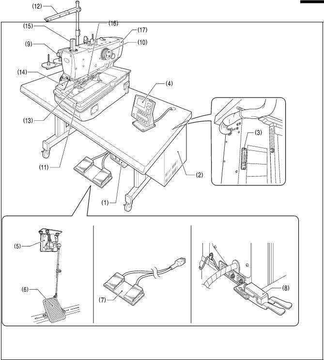
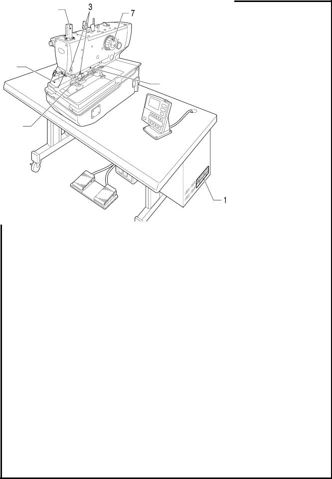
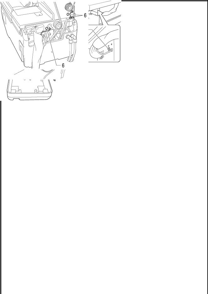
1. NAMES OF MAJOR PARTS
1. NAMES OF MAJOR PARTS
0335B
The accessory switches shown below to use for starting the sewing machine will vary depending on the destination.
(1) |
Power switch |
(7) |
2-pedal foot switch |
(2) |
Control box |
(8) |
Hand start switch |
(3) |
CF slot* |
(9) |
STOP switch |
(4) |
Operation panel |
(10) |
Upper shaft pulley |
(5) |
Treadle unit |
(11) |
Feed base |
(6) |
Treadle (commercially-available) |
(12) |
Cotton stand |
Safety devices: |
|
|
|
(13) |
Finger guard |
(16) |
Needle guide cover |
(14) |
Eye guard |
(17) |
Belt cover |
(15)Needle bar guard
*: CFTM is a trademark of SanDisk Corporation.
1 |
RH-9820 |
2. MACHINE SPECIFICATIONS
2. MACHINE SPECIFICATIONS
2-1. Specifications
|
Thread trimmer |
Lower thread trimmer |
|
|
Long type |
Short type |
|
|
|
||
-00 |
O |
- |
- |
-01 |
O |
O |
- |
-02*1 |
O |
- |
O |
*1:
*2:
-02 specifications are divided into L1422 to L3422 specifications depending on the sewing lengths, so please specify the sewing length when ordering.
This is not covered by specification designations, but compatibility is possible by replacement of gauge parts. (Ask the place of purchase for details.)
SPECIFICATIONS |
RH-9820-00 |
|
RH-9820-01 |
|
RH-9820-02 |
Use |
Men’s clothes, ladies’ clothes |
|
Jeans and work clothes |
||
Sewing speed |
1,000 - 2,500 rpm (Setting possible in units of 100 rpm) |
||||
|
Without bartack |
|
Without bartack |
|
Without bartack |
|
Taper bartack |
|
Taper bartack |
|
Taper bartack |
Sewing shape |
Straight bartack |
|
Straight bartack |
|
Straight bartack |
|
Round bartack |
|
Round bartack |
|
Round bartack |
|
Circular stitch |
|
Circular stitch |
|
|
|
|
|
|
|
L1422: 14 - 22 mm *2 |
|
|
|
|
|
L1826: 18 - 26 mm |
Sewing length |
5 - 50 mm |
|
5 - 42 mm |
|
L2230: 22 - 30 mm |
|
|
|
|
|
L2634: 26 - 34 mm *2 |
|
|
|
|
|
L3442: 34 - 42 mm *2 |
Stitch pitch |
|
|
0.5 - 2.0 mm |
|
|
Zigzag width |
1.5 - 5.0 mm (Max. 4.0 mm with mechanism, Max. 1.0 mm with software) |
||||
Taper bartack length |
|
|
0 - 20 mm |
|
|
Work clamp height |
Standard 12 mm (up to 16 mm possible) |
|
16 mm |
||
Starting method |
Foot switch (treadle type, 2-pedal type) or hand start switch |
||||
Feed mechanism |
|
Intermittent feed by three pulse motors (X, Y, θ) |
|||
Needle |
|
DO x 558 80 - 120 Nm (Schmetz 558) |
|
||
Safety devices |
Built-in emergency stop function and automatic stopping device which stops the machine when the |
||||
|
|
|
safety circuit is activated |
|
|
Upper shaft motor |
|
|
AC servo motor (4-pole, 550 W) |
|
|
Air pressure |
|
|
Main regulator: 0.5 MPa |
|
|
|
Hammer pressure regulator: 0.4 MPa |
|
|||
|
|
|
|||
Air consumption |
|
|
43.2 l/min (8 cycles/min) |
|
|
Power supply |
Single-phase 100V/220V, Three-phase 200V/220V/380V/400V 400 VA |
||||
Weight |
Machine head: Approx. 120 kg, Operation panel: Approx. 0.6 kg |
||||
|
Control box: 14.2 - 16.2 kg (Varies depending on destination) |
||||
RH-9820 |
2 |

2. MACHINE SPECIFICATIONS
2-2. Sewing shapes
Eyelet buttonhole
Without bartack |
Taper bartack |
Straight bartack |
Round bartack |
|
|
|
|
|
Straight buttonhole |
|
|
Without bartack |
Taper bartack |
Straight bartack |
Round bartack |
|
|
|
|
Circular stitch |
|
|
|
|
|
|
|
0536B-0539B
0540B-0543B
0544B
3 |
RH-9820 |

|
|
|
|
3. INSTALLATION |
||
|
|
|
|
|
||
3. INSTALLATION |
|
|
|
|
||
|
|
|
CAUTION |
|
|
|
Machine installation should only be carried out by a |
All cords should be secured at least 25 mm away from |
|
||||
qualified technician. |
|
|
|
any moving parts. Furthermore, do not excessively |
|
|
Contact your Brother dealer or a qualified electrician |
bend the cords or secure them too firmly with staples. |
|
||||
If this is not observed, there is the danger that fire or |
|
|||||
for any electrical work that may need to be done. |
|
|||||
electric shocks could occur. |
|
|
||||
The sewing machine weighs approximately 120 kg. |
|
|
||||
Be sure to connect the ground. |
|
|
||||
Installation of the sewing machine and adjustment of |
|
|
||||
If the ground connection is not secure, you run a high |
|
|||||
the table height should be carried out by four or more |
|
|||||
risk of receiving a serious electric shock, |
and |
|
||||
people. |
|
|
|
|
||
|
|
|
problems with correct operation may also occur. |
|
|
|
Do not connect the |
power |
cord |
until installation is |
|
|
|
Install the safety covers to the machine head |
and |
|
||||
complete. If this is not done, the sewing machine may |
|
|||||
motor. |
|
|
||||
operate if the start switch is pressed by mistake, which |
|
|
||||
|
|
|
||||
could result in serious injury. |
|
|
|
|
|
|
Hold the machine head with both hands when tilting it |
|
|
|
|||
back or returning |
it to |
its |
original position. |
|
|
|
In addition, do not subject the machine head to extra |
|
|
|
|||
force while it is tilted back. If this is not observed, the |
|
|
|
|||
machine head may lose balance and fall over |
|
|
|
|||
(together with the table), and injury or damage to the |
|
|
|
|||
sewing machine may result. |
|
|
|
|
|
|
|
|
|
|
|
|
|
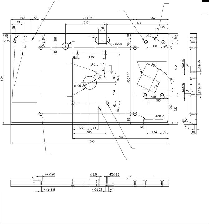
3-1. Table processing diagram
•Use a table with legs which is strong enough to bear the weight of the sewing machine (120 kg) and which can also withstand vibration. Use a table with a top thickness of 49 - 60 mm.
NOTE:
If the thickness of the table exceeds 60 mm, the accessory bolts and the cables coming from the machine head may not be long enough.
•If using casters, use ones which can bear the total weight of sewing machine and table.
•Check that the control box is at least 10 mm away from the leg. If the control box and the leg are too close together, it may result in incorrect sewing machine operation.
•The method of processing the table varies depending on whether the machine head is sitting on the table or embedded into the table. Refer to the processing diagrams for each respective setting-up method and drill the holes as appropriate.
RH-9820 |
4 |
3. INSTALLATION
3-1-1. When setting up on top of the table
2 x 4 mm dia. 20 depth
(from underneath table) For operation panel cord For pneumatic unit
For control box
For cords
For cords Φ50
4 x 2 mm dia. 10 depth For operation panel
For treadle unit
2 x 4 mm dia.
20 depth
(From underneath table)
For valve unit
For oiler
For cotton stand
2 x 2 mm dia. 10 depth (from underneath table) For power switch
For bed base
For table leg
For provisionally holding bed base
Melamine veneer panel
0338B
5 |
RH-9820 |

3. INSTALLATION
3-1-2. When embedding into the table
When embedding the machine head into the table, some extra components will be required, so contact the place of purchase for further details.
NOTE:
When embedding the machine head into the table, be sure to install the L-shaped table reinforcement plates. (Refer to “3-3. Installing the table reinforcement plates (embedded installation only)”.)
For pneumatic unit
For L-shaped reinforcement plates |
For operation panel cord |
|
For control box
Shaded area should |
For operation panel |
|
be C10 |
||
4 x 2 mm dia. 10 depth |
||
|
4 x 4 mm dia.
20 depth
(From underneath table)
For valve unit
For cotton stand
2x 2mm dia. 10 depth (from underneath table)
For power switch
For table leg
For bed support plate
Melamine veneer panel
0339B
RH-9820 |
6 |
3. INSTALLATION
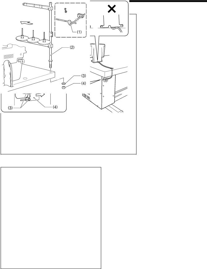
3-2. Installing the control box
CAUTION
Before installing the control box, take steps to make sure that the control box does not fall down. If this is not done, injury to feet or damage to the control box may result.
|
|
|
Before installing the control box (1), |
|||
|
|
0340B |
||||
|
|
|||||
|
|
check that the model plate (2) on the |
||||
|
|
|
||||
|
|
|
control box (1) is “RX9820” to indicate |
|||
|
|
|
that it is an RX-control box for RH-9820 |
|||
|
|
|
sewing machines. |
|
||
|
|
|
(1) |
Control box |
|
|
|
|
|
(3) |
Bolts [4 pcs.] |
|
|
|
|
|
(4) |
Plain washers [4 pcs.] |
|
|
|
|
|
(5) |
Nuts [8 pcs.] |
|
|
|
|
|
NOTE: |
|
|
|
|
|
|
|
Check that the control box (1) is at |
||
|
|
|
|
least 10 mm away from the leg. If |
||
|
|
|
|
the control box (1) and the leg are |
||
|
|
|
|
too close together, it may result in |
||
|
|
|
|
incorrect |
sewing |
machine |
|
|
|
|
operation. |
|
|
|
|
|
|
|
|
|
10mm or more Leg
0404B
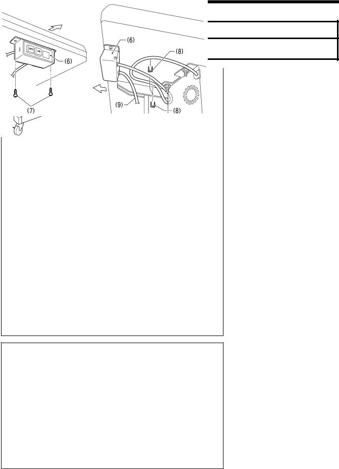
(6) Power switch
(7) Screws [2 pcs.]
(8) Staples [5 pcs.]
Operator
* Use the remaining two staples to secure the power cord (9) in a position that matches the position of the wall outlet.
NOTE:
Take care when tapping in the staples (8) to make sure that they do not pierce the power cord (9).
Operator
0341B
7 |
RH-9820 |

3. INSTALLATION
3-3. Installing the table reinforcement plates (embedded installation only)
(1) L-shaped reinforcement plates [2 pcs.]
(2) Bolts [10 pcs.]
(3) Plain washers [10 pcs.]
(4) Spring washers [10 pcs.]
(5) Nuts [10 pcs.]
0342B
3-4. Installing the machine head
3-4-1. When setting up on top of the table
<Only when using the treadle>
Before installing the machine head, install the three treadle mounting bolts (A) to the table.
* Insert the bolts (A) securely so that their heads do not protrude out from the top of the table.
(Refer to “3-12. Installing the treadle unit (when using the treadle)”.)
Table
0343B |
(Continued on next page) |
RH-9820 |
8 |
3. INSTALLATION
 CAUTION
Always be sure to install the stopper bolt before tilting back the machine head in step 4 below. If this is not done, the machine head will tip over and fall down, and injury or damage to the machine head may result.
0344B
0345B
0346B
(rear)
Provisionally secure
gap
Provisionally secure
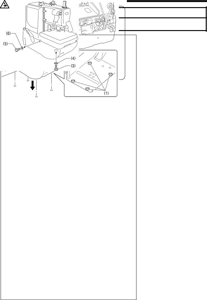
1.Check that the four bed base cushions (1) have all been installed to the bottom of the bed base, and then place the machine head onto the table.
NOTE:
•When placing the machine head onto the table, have four or more people hold the machine head by the places indicated by the four  locations in the illustration.
•Do not hold by the head support lever (2).
2.Use one of the four bolts (3) and a plain washer (4) to provisionally secure the bed base to the table from underneath the table.
3.After provisionally securing the bed base, remove the fixing bolt (5) and washer (6).
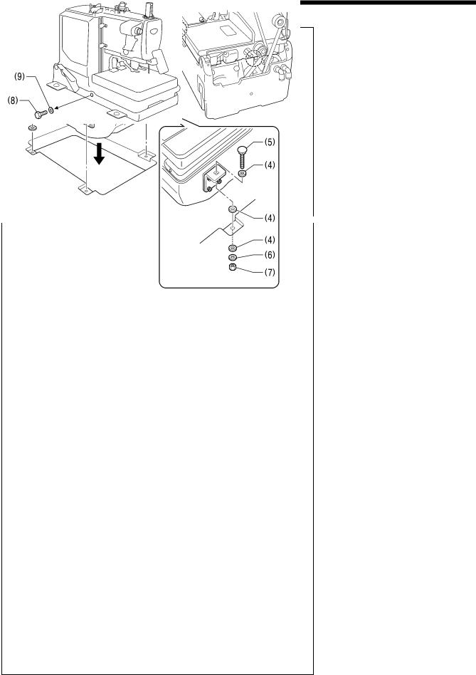
4.Tilt back the machine head, and then install the remaining three of the four bolts (3) to the other three places in the bed base. (Refer to “3-5. Tilting back and returning the machine head” for details on tilting back the machine head.)
(7) Washers [4 pcs.]
(8) Rubber sheets [4 pcs.]
(9) Washers (large) [4 pcs.]
(10) Nuts [4 pcs.]
NOTE:
Do not over tighten the bolts (3) so much that a gap is produced between the table and the bed base.
5.Remove the bolt (3) and washer (4) that were used to provisionally secure the bed base, and install them to the one remaining location.
NOTE:
The fixing bolts (5) and washers (6) are needed when moving the machine head, so store them in a safe place.
9 |
RH-9820 |
3. INSTALLATION
3-4-2. When embedding into the table
(1) Bed support plates [4 pcs.]
(2) Bolts [16 pcs.]
* Install so that they are horizontal to the bed base.
|
0347B |
|
|
|
|
|
NOTE: |
|
|
|
|
|
||
|
|
|
||
|
|
• |
When placing the machine head |
|
|
|
|
onto the table, have four or more |
|
|
|
|
people hold the machine head by the |
|
|
|
|
places indicated by the |
locations |
|
|
• |
in the illustration. |
|
|
|
Do not hold by the head support |
||
|
|
|
lever (3). |
|
|
(4) |
Rubber sheets [4 pcs.] |
|
|
|
(5) |
Bolts [4 pcs.] |
|
|
(rear) |
(6) |
Washers (large) [4 pcs.] |
|
|
(7) |
Nuts [4 pcs.] |
|
||
After installing the machine head, remove the fixing bolts (8) and washers
(9).
NOTE:
The fixing bolts (8) and washers (9) are needed when moving the machine head, so store them in a safe place.
0348B
0349B
RH-9820 |
10 |
3. INSTALLATION
3-5. Tilting back and returning the machine head
 CAUTION
Hold the machine head with both hands when tilting it back or returning it to its original position. In addition, do not subject the machine head to extra force while it is tilted back. If this is not observed, the machine head may lose balance and fall over (together with the table), and injury or damage to the sewing machine may result.
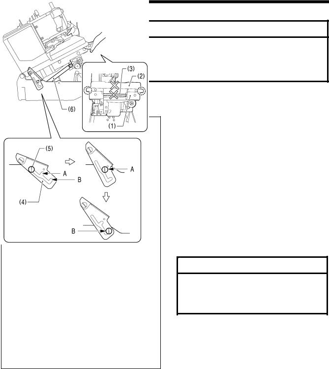
Do not hold the feed base (2) and the feed guide shaft (3). If this is not observed and the feed base (2) or feed guide shaft (3) come off, the machine head may fall down and injury or damage to the machine head may result.
The machine head can be tilted back and returned to one of two heights.
NOTE:
Always be sure to turn off the power switch before tilting back and returning the machine head.
0352B
First step
Second step
Tilting back the sewing machine head
1.Hold the bed (1) at both sides (at the places indicated by  in the illustration) with both hands.
2.To tilt back to the first step:
Gently lift up the machine head until the head support lever (4) securely engages section A of the hinge support shaft (5) (until a click is heard).
3.To tilt back to the second step:
Remove the head support lever (4) from section A of the hinge support shaft (5), and then gently lift up the machine head until the head support lever (4) securely engages section B.
NOTE:
The machine head will be momentarily stopped by the gas spring (6) immediately before it rises to the second step, but it will not be locked at this point. Lift the machine head until the head support lever (4) securely engages section B of the hinge support shaft
(5).
 CAUTION
Be sure to check that the head support lever (4) and the hinge support shaft (5) are engaged. If they are not engaged, the machine head may suddenly return to its original position and injury may result.
<Returning the machine head to its original position>
1.To return the machine head from the second step:
After lifting up the machine head, remove the head support lever (4) from section B of the hinge support shaft (5), and then hold the bed at both sides and gently return it to its original position.
*The machine head will start returning until the gas spring (6) starts to operate, so support the machine head securely with both hands.
*When the machine head is returned to the first step, the head support lever will lock onto section A.
2.To return the machine head from the first step:
After gently lifting up the machine head, remove the head support lever (4) from section A of the hinge support shaft (5), and then hold the bed at both sides and gently return it to its original position.
11 |
RH-9820 |
3. INSTALLATION
3-6. Installing the belt cover and feed bar cover U
0351B |
0350B |
0619B
(1)Belt cover
(2)Screws [4 pcs.]
•Before installing the belt cover, pass the cords through the belt cover notch (3).
NOTE:
•Be careful not to clamp the cords when installing the belt cover. If care is not taken, the belt cover and cords may become damaged.
•If using the embedded installation method, check that the belt cover (1) does not touch the table when the machine head is tilted back.
(4)Feed bar cover U
(5)Screws [2 pcs.]
NOTE:
If the screws (5) are tightened too much, the feed bar cover U (4) may become cracked.
3-7. Installing the oiler
0353B
The oiler should be installed while the machine head is tilted back.
(Refer to “3-5. Tilting back and returning the machine head”.)
(1)Dust oiler support
(2)Screws [2 pcs.]
(3)Oiler
(4)Oiler spring pin
•Use a hammer or similar to tap the pin (4) so that its head is flush with the base of the oil pan (5).
NOTE:
When tapping in the pin (4), check that the knot in the wick (6) is below the top of the pin (4) as shown in the illustration at left. If the knot is above the pin (4), it may become hit by the hammer and this may cause the wick (6) to break.
•Once installation is complete, return the machine head to its original position.
0354B
RH-9820 |
12 |
3. INSTALLATION
3-8. Installing the operation panel
0355B
(1)Operation panel
(2)Screws [4 pcs.]
1.Pass the cord of the operation panel (1) through the table hole.
2.Loosen the two screws (3) at the rear of the control box, open the cord presser plate (4) in the direction of the arrow, and pass the cord through the hole into the box. (Refer to “3-1. Table processing diagram” for details on the installation position for the operation panel.)
NOTE:
Check that the operation panel cord is not being clamped when screwing the operation panel into the table. The cord may become damaged if it is clamped.
0356B
3-9. Installing the cotton stand
Operator
Install the cotton stand so that it is at the far left of the table when looking from the front of the sewing machine.
*Do not use the thread guide (1) which is provided a an accessory with the cotton stand.
(2)Cotton stand
(3)Washer
(4)Nut
NOTE:
•Tighten the nut to secure the cotton stand firmly so that it will not move.
•The cotton stand can also be installed on the far right side of the table, but if this is done, the threading method will change. (Refer to “4-5. Threading the thread when the cotton stand is installed on the right side”.)
0357B
13 |
RH-9820 |
3. INSTALLATION
3-10. Installing the air unit and valve unit
Install to the underside of the table. (Refer to “3-1. Table processing diagram” for the installation positions.)
(1) |
Air unit |
(2) |
Screws [2 pcs.] |
(3) |
Valve unit |
(4) |
Screws [2 pcs.] |
(5) |
Air tube No. 4 |
Insert air tube No. 4 (5) into the joint (6) and the joint (7).
NOTE:
• Install the air unit (1) so that it does not touch the table leg.
• Be careful to avoid injury from items such as sewing machine parts and the corners of table drawers during installation.
0358B
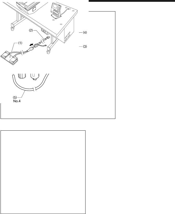
3-11. Installing the 2-pedal foot switch (when using the 2-pedal foot switch)
(1) 2-pedal foot switch
(2) Foot switch conversion harness
Pass the connector of the foot switch conversion harness (2) into the control box through the hole in the rear of the control box. (Refer to “3-8. Installing the operation panel”.)
<2-pedal foot switch operation method>
When the work clamp switch (left side) is depressed, the work clamp will be lowered, and when the start switch (right side) is depressed, the sewing machine will start.
Work clamp switch
Start switch
4923Q
0361B
RH-9820 |
14 |
3. INSTALLATION
3-12. Installing the treadle unit (when using the treadle)
3-12-1. When setting up on top of the table
NOTE:
Before installing the machine head, install the three treadle unit mounting bolts (A) to the table. (Refer to “3-4-1. When setting up on top of the table”.)
(1) |
Treadle unit |
(2) |
Plain washers [3 pcs.] |
(3) |
Spring washers [3 pcs.] |
(4) |
Nuts [3 pcs.] |
Pass the connector of the treadle unit (1) into the control box through the hole in the rear of the control box. (Refer to “3-8. Installing the operation panel”.)
* Use a commercially-available treadle (5) and connecting rod (6).
<Treadle operation method>
When the treadle (5) is depressed to the 1st step, the work clamp will be lowered, and when it is depressed to the 2nd step, the sewing machine will start.
1st step 2nd step
4441Q
0359B
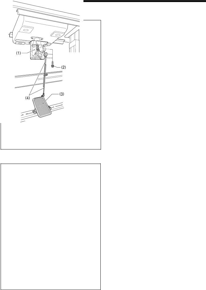
3-12-2. When embedding into the table
(1) Treadle unit
(2) Screws [3 pcs.]
Pass the connector of the treadle unit (1) into the control box through the hole in the rear of the control box. (Refer to “3-8. Installing the operation panel”.)
* Use a commercially-available treadle (3) and connecting rod (4).
<Treadle operation method>
When the treadle (3) is depressed to the 1st step, the work clamp will be lowered, and when it is depressed to the 2nd step, the sewing machine will start.
1st step 2nd step
4441Q
0360B
15 |
RH-9820 |
3. INSTALLATION
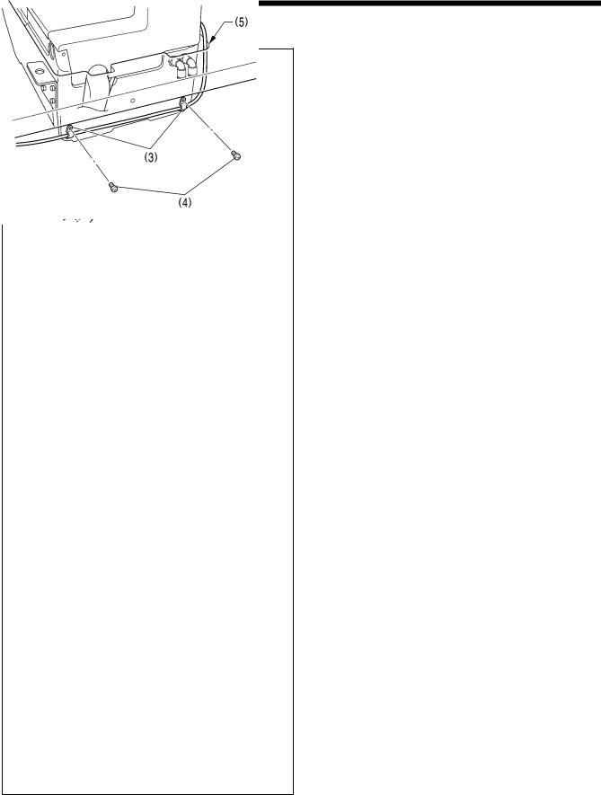
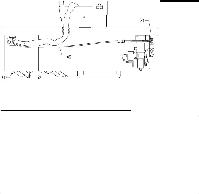
3-13. Installing the hand start switch (when using the hand start switch)
0362B
[When setting up on top of the table]
0363B
[When embedding into the table]
(1)Hand start switch
(2)Screws [2 pcs.]
(3)Cord holders [3 pcs.]
(4)Screws [3 pcs.]
*When setting up on top of the table, use only two of the cord holders (3) and screws (4).
Pass the cord of the hand start switch (1) through the table hole (5), and pass the connector into the control box through the hole in the rear of the control box. (Refer to “3-8. Installing the operation panel”.)
[When setting up on top of the table]
Insert the cord into the quick tube (6), and then pass it through the table hole (5).
*This is to prevent damage from the cord rubbing against the table hole (5) when the machine head is tilted back and returned.
<Hand start switch operation method>
When the work clamp switch (left side) is depressed, the work clamp will be lowered, and when the start switch (right side) is depressed, the sewing machine will start.
Start switch
Work clamp switch
0364B
0385B
(Continued on next page)
RH-9820 |
16 |
3. INSTALLATION
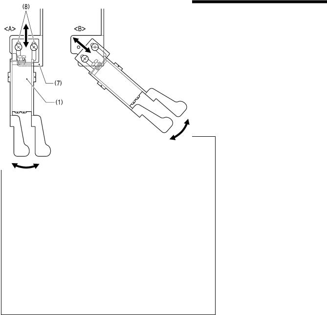
<Adjusting the hand start switch position>
Adjust the position of the hand start switch (1) as follows so that it is in an easy-to-use position.
[Forward/back and vertical position]
1.Loosen the two screws (2), and then move the hand start switch mounting plate (7) forward, back, up or down to adjust its position.
2.Once adjustment is complete, securely tighten the screws (2).
0311B
[Forward/back and sideways position]
•The hand start switch mounting plate
(7) has three screw holes in it. You can select the installation position from either <A> or <B> shown in the illustration by changing the screw holes used by the screws (8).
•In addition, when the screws (8) are loosened, the hand start switch (1) can be moved forward, back and sideways to adjust its position. Once adjustment is complete, securely tighten the screws (8).
0312B
17 |
RH-9820 |
3. INSTALLATION
3-14. Connecting the cords
3-14-1. Connecting the connectors inside the control box
0365B
1.Remove the eight screws (1), and then remove the control box cover
(2).
2.Gently tilt back the machine head.
3.Pass the cord bundle through the table hole, and then pass it into the control box through the hole in the rear of the control box.
0524B
4.Pass the hammer valve harness (3) into the control box through the hole in the rear of the control box.
(4) Hammer valve
5.Insert each of the connectors as shown in the illustration and table on pages 19 and 20.
NOTE:
•Check that the connectors are facing the correct way, and then insert them firmly until they lock into place.
•Secure the cables with fastening bands and cord clamps, while being careful not to pull on the connectors.
(Continued on next page)
RH-9820 |
18 |
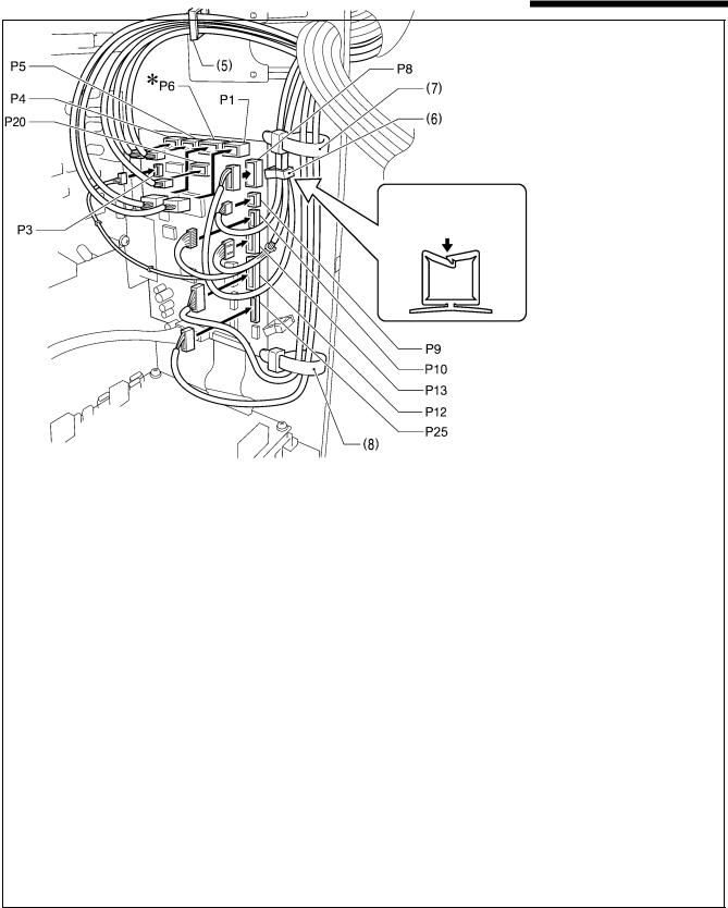
3. INSTALLATION
<Main P.C. board>
Securely lock the cord clamps.
* <If using the 2-pedal foot switch>
Be sure to make the ground connection. (Refer to “3-14-2. Connecting the ground wire”.)
Connectors |
At main P.C. board |
Cord clamp |
|||
Insertion location |
|||||
|
|
||||
X pulse motor encoder 5-pin white |
P20 |
(X-ENC) |
(5) |
||
Y pulse motor encoder 5-pin blue |
P4 |
(Y-ENC) |
(5) |
||
θ-feed motor encoder 5-pin black |
P5 |
(P-ENC) |
(5) |
||
Treadle, 2-pedal foot switch, hand start switch |
P6 |
(FOOT) |
(5) |
||
10-pin |
|
|
|
|
|
Operation panel 8-pin |
P1 |
(PANEL) |
(5) |
||
Hammer position sensor |
P3 |
(CUTTER) |
(6) |
||
Machine head safety switch 3-pin |
P9 |
(HEAD-SW) |
(6) |
||
(Y home position, cooling fan) sensor 12-pin |
P8 |
(SENSOR1) |
(6) |
||
STOP switch 6-pin |
P13 |
(HEAD) |
(6) |
||
(Zigzag check, low thread trimming OFF) sensor |
P10 |
(SENSOR2) |
(6) |
||
6-pin |
|
|
|
|
|
Valve harness 12-pin |
P12 |
(AIR1) |
(7), (8) |
||
Hammer valve harness 10-pin |
P25 |
(AIR2) |
(7), (8) |
||
0366B
19 |
RH-9820 |

3. INSTALLATION
<Power supply motor P.C. board>
<Removal>
Press the tabs.
<Securing method>
<PMD P.C. board>
*: Be sure to make the ground connection. (Refer to “3-14-2. Connecting the ground wire”.)
|
At power supply motor |
|
||
Connectors |
|
P.C. board |
Cord clamp |
|
|
|
Insertion location |
|
|
Machine head memory 7-pin |
P3 |
(HEAD-M) |
(6) |
|
Upper shaft motor 3-pin |
P4 |
(UVW) |
(7) |
|
Synchronizer 14-pin |
P5 |
(SYNC) |
(7), (8) |
|
Connectors |
|
At PMD P.C. board |
Cord clamp |
|
|
Insertion location |
|||
|
|
|
||
θ-feed motor 4-pin black |
P3 |
(PPM) |
(7), (8) |
|
(Gimp clamp, lower tension release) solenoid |
P6 |
(SOL1) |
(7), (8) |
|
6-pin |
||||
|
|
|
||
Upper tension release solenoid 4-pin |
P7 |
(SOL2) |
(7), (8) |
|
Y-feed motor 4-pin blue |
P8 |
(YPM) |
(7), (8) |
|
X-feed motor 4-pin white |
P10 (XPM) |
(7), (8) |
||
NOTE: |
|
Route the X-feed, Y-feed and θ-feed motor harnesses so that they do not touch the PMD P.C. board. |
0367B |
(Continued on next page)
RH-9820 |
20 |
3. INSTALLATION
0368B
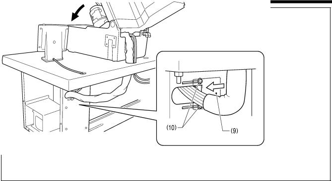
6.Close the cord presser plate (9) in the direction of the arrow, and secure it by tightening the two screws (10).
NOTE:
•Make some slack in the cords outside the control box so that the cords do not get pulled too tightly inside the control box.
•Securely close the cord presser plate (9). If dust gets inside the control box, it may cause problems with operation.
7.Check that the cords do not get pulled, and then gently return the machine head to its original position.
21 |
RH-9820 |
Loading...