

Broan BU224WH, BU224SS, BU230WW, BU230WH, BU230BL INSTALLATION INSTRUCTIONS AND OPERATION MANUAL
...
BU2 SERIES
4-WAY CONVERTIBLE
RANGE HOOD
READ AND SAVE THESE INSTRUCTIONS
REGISTER YOUR PRODUCT ON LINE AT :
WWW.BROAN.CA
!
INTENDED FOR DOMESTIC COOKING ONLY.
WARNING
TO REDUCE THE RISK OF FIRE, ELECTRIC SHOCK OR INJURY
TO PERSONS, OBSERVE THE FOLLOWING:
1. Use this unit only in the manner intended by the manufacturer. If you
have questions, contact the manufacturer at the address or telephone
number listed in the warranty.
2. Before servicing or cleaning unit, switch power off at service panel
and lock service disconnecting means to prevent power from being
switched on accidentally. When the service disconnecting means
cannot be locked, securely fasten a prominent warning device, such as
a tag, to the service panel.
3. Installation work and electrical wiring must be done by qualified
personnel in accordance with all applicable codes and standards,
including fire-rated construction codes and standards.
4. Sufficient air is needed for proper combustion and exhausting of
gases through the flue (chimney) of fuel burning equipment to prevent
backdrafting. Follow the heating equipment manufacturer’s guidelines
and safety standards such as those published by the National Fire
Protection Association (NFPA) and the American Society for Heating,
Refrigeration and Air Conditioning Engineers (ASHRAE) and the local
code authorities.
5. When cutting or drilling into wall or ceiling, do not damage electrical
wiring and other hidden utilities.
6. Ducted fans must always be vented to the outdoors.
7. Do not use this unit with any additional solid-state speed control device.
8. To reduce the risk of fire, use only metal ductwork.
9. This unit must be grounded.
10. When applicable local regulations comprise more restrictive installation
and/or certification requirements, the aforementioned requirements
prevail on those of this document and the installer agrees to conform to
these at his own expense.
TO REDUCE THE RISK OF A RANGE TOP GREASE FIRE:
a) Never leave surface units unattended at high settings. Boilovers cause
smoking and greasy spillovers that may ignite. Heat oils slowly on low
or medium settings.
b) Always turn range hood ON when cooking at high heat or when
flambeing food (i.e.: Crêpes Suzette, Cherries Jubilee, Peppercorn
Beef Flambé).
c) Clean ventilating fans frequently. Grease should not be allowed to
accumulate on fan, filters or in exhaust ducts.
d) Use proper pan size. Always use cookware appropriate for the size of
the surface element.
INSTALLER: Leave this manual to the homeowner.
HOMEOWNER: Use and care information on page 5.
!
WARNING
TO REDUCE THE RISK OF INJURY TO PERSONS IN THE EVENT
OF A RANGE TOP GREASE FIRE, OBSERVE THE FOLLOWING*:
1. SMOTHER FLAMES with a close-fitting lid, cookie sheet or metal tray,
then turn off the burner. BE CAREFUL TO PREVENT BURNS. IF THE
FLAMES DO NOT GO OUT IMMEDIATELY, EVACUATE AND CALL
THE FIRE DEPARTMENT.
2. NEVER PICK UP A FLAMING PAN — You may be burned.
3. DO NOT USE WATER, including wet dishcloths or towels — This could
cause a violent steam explosion.
4. Use an extinguisher ONLY if:
A. You own a Class ABC extinguisher and you know how to operate it.
B. The fire is small and contained in the area where it started.
C. The fire department has been called.
D. You can fight the fire with your back to an exit.
* Based on “Kitchen Fire Safety Tips” published by NFPA.
CAUTION
1. For indoor use only.
2. For general ventilating use only. Do not use to exhaust hazardous or
explosive materials and vapors.
3. To avoid motor bearing damage and noisy and/or unbalanced impellers,
keep drywall spray, construction dust, etc. off power unit.
4. Your hood motor has a thermal overload which will automatically shut
off the motor if it becomes overheated. The motor will restart when it
cools down. If the motor continues to shut off and restart, have the hood
serviced.
5. For best capture of cooking impurities, the bottom of the hood should
be at a minimum of 18” and at a maximum of 24” above the cooking
surface.
6. To reduce the risk of fire and to properly exhaust air, be sure to duct
air outside — Donot exhaust air into spaces within walls or ceiling or into
attics, crawl space or garage.
7. When installing, servicing or cleaning the unit, it is recommended to wear
safety glasses and gloves.
8. Please read specification label on product for further information and
requirements.
!
99045994A
For Non-ducted (Duct free) Installation:
IMPORTANT
a) Purchase non-ducted filter separately, model 41F.
b) Remove and discard damper/duct connector and grille cover
(See Step 3 in “Preparing the range Hood,” on page 3).
c) Follow all steps except steps inside dotted lines.
For Ducted Installation:
Follow all steps, including steps inside dotted lines.
FIG. 1A
WALL CAP 639 OR 649
FIG. 1B
WALL CAP 639 OR 649
TOOLS AND MATERIAL REQUIRED
TOOLS
Drill
1¼" Spade bit
Pliers
For ducted installations ONLY:
Flat blade and
Phillips screwdriver
Tape measure or ruler
and pencil
Saber saw
Metal snips
MATERIALS
Electrical wiring and supplies of type to comply with local codes
Roof or wall cap
Duct and metal foil duct tape
Roof cement or caulk
For installation on kitchen cabinets with recess bottoms only:
Two 1" x 2" x 12" (approximate length) wood strips (purchase locally)
Four 1¼" long flat heat wood screws (purchase locally) to fasten
strips to cabinet bottom
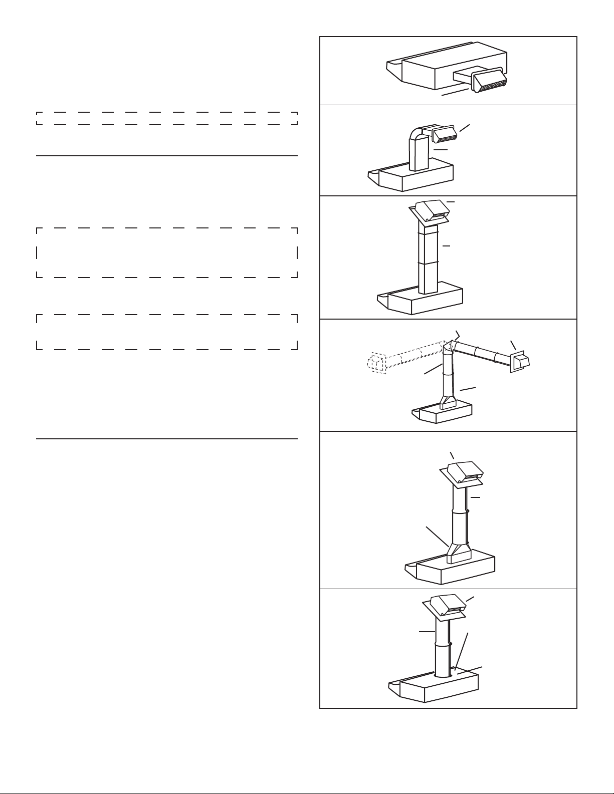
PLANNING DUCTWORK INSTALLATION
Begin planning ductwork by deciding where the duct will run between
the range hood and the outside. For best performance, use the shortest
possible duct run and a minimum number of elbows. There are several
choices shown - FIGS. 1A - 1F.
If needed, a 3¼” x 10” rectangular ducting range hood can be converted to
a round duct by means of a transition.
FIG. 1A. Ducting directly through the wall (for range hoods mounted on an
exterior wall). Shown are two ways to duct through an outside wall. If a wall
cap is used directly off the back of the hood, special care must be taken to
make sure that the damper in the damper/duct connector on the hood and
damper in the wall cap do not interfere with each other when the hood is
operating. This could result in either inadequate air delivery or back drafts.
If this condition does exist, remove the hood damper flap. Sometimes when
using a wall cap it is easier to duct vertically and then use an elbow as
shown in FIG. 1B.
FIG. 1C. Ducting straight up through the roof using 3¼” x 10” rectangular
duct. (For single story installations.)
FIG. 1D. Ducting between the ceiling joists (for multi-story installations) or
through the soffit space above the cabinets (where the soffit connects to
an outside wall).
FIG. 1E. Straight up through the roof using 3¼” x 10” to 6” round duct
transition and 6” round duct (for single-story installations).
FIG. 1F. Straight up through the roof using 7” round duct (for single-story
installations, 7” round adapter plate not included, part number SR680508).
FIG. 1C
FIG. 1D
FIG. 1E
FIG. 1F
7” ROUND DUCT 407
ADJUSTABLE ELBOW 419
6” ROUND DUCT 406
ROOF CAP 634 OR 644
3¼” X 10” TO 6” ROUND
TRANSITION 411
DUCT
3¼” X 10” DUCT 401
ROOF CAP 634 OR 644
3¼” X 10” DUCT 401
WALL CAP 641
3¼” X 10” TO 6” ROUND
TRANSITION 411
DUCT
6” ROUND DUCT 406
ROOF CAP 634 OR 644
OPTIONAL DAMPER
MODEL BP87
7” ROUND DUCT PLATE
SR680508
- 2 -
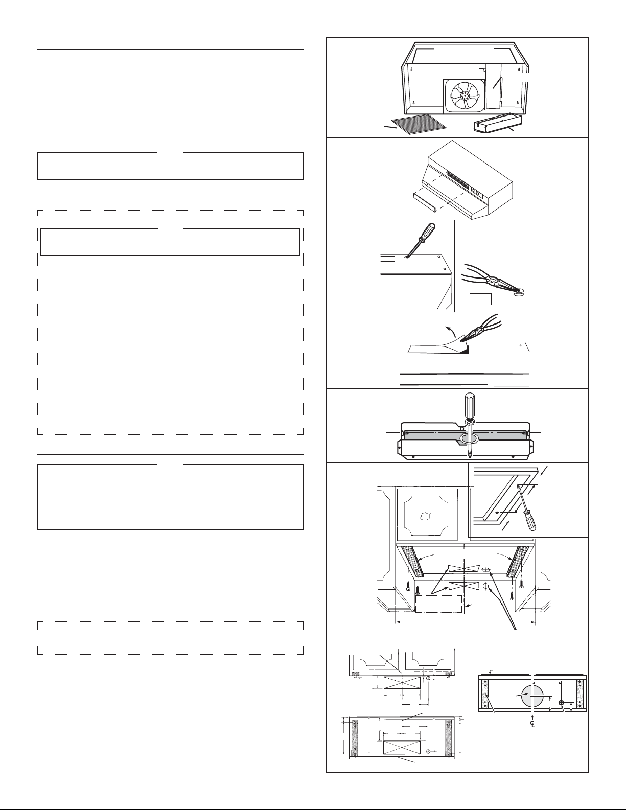
PREPARING THE RANGE HOOD
1. Unpack hood and check contents. You should have:
1 - Aluminum filter
1 - 3¼” x 10” Damper/duct connector
(mounted inside of hood for shipping only) (save the screws)
2. Remove wiring box cover. Under cover find the parts bag containing
loose hardware.
For non-ducted installation only
3. For non-ducted installation, remove grille cover from front (or inside) of
hood. (FIG. 3)
NOTE
The grille on front of hood must be open and visible for hood
to function in non-ducted mode.
4. Remove either top or rear electrical knockout depending upon whether
wiring will enter hood from wall or cabinet. (FIG. 4)
FIG. 2
ALUMINUM FILTER
FIG. 3
KEYHOLE SLOTS (4)
WIRING BOX COVER
DAMPER/DUCT CONNECTOR
DUCTED INSTALLATION ONLY
NOTE
The grille cover must be installed as shown in FIG. 3
to function in ducted mode.
5. Remove appropriate duct knockout on hood by inserting screwdriver
into edge of knockout and breaking tabs holding knockout to hood.
You may have to tap screwdriver with hammer to break tabs. Peel
knockout back with pliers. (FIG. 5)
6. Fit damper/duct connector over opening and secure in place with
black sheet metal screws. (FIG. 6)
Hinge pins and damper/duct connector should be toward top of hood
for ducting through wall or toward back of hood for ducting through
cabinet above hood. Seal joint between damper/duct connector and
hood with duct tape.
7. 7” round ducted discharge only: Purchase separately the 7” round
duct plate (part no. SR680508). For best performance, line up the 7”
round duct plate with the 7” round opening on hood. Mount duct plate
to hood with 2 screws included with duct plate and 2 screws from
3¼” x 10” damper (1 screw per side). Install a 7” round damper
(purchase separately). Damper flap must open freely in direction of air
flow (away from range hood).
PREPARING THE INSTALLATION LOCATION
NOTE
MOUNT HOOD SO THAT BOTTOM OF HOOD IS 18”-24” ABOVE
COOKING SURFACE. TOP FRONT EDGE OF HOOD SHOULD BE
FLUSH WITH FRONT OF CABINET FRAME.
IF DISTANCE BETWEEN WALL AND FRONT OF CABINET FRAME
IS MORE THAN 12” THERE WILL BE A SPACE BETWEEN BACK OF
HOOD AND WALL. THIS IS NORMAL.
OMIT STEP 8 if range hood will be installed under cabinets with flush
bottom.
8. (For installation on recessed bottom cabinets only.) Attach a wood filler
strip at each side of recessed area under cabinet. (Use two 1” x 2” strips
cut to length.) If recess is more than 1” use thicker strips. Attach strips
with 1¼” screws about 3” from each end. See FIG. 7.
9. Measure and mark the following (FIGS. 7 & 8):
a) Electrical line opening
b) Duct opening
10. Drill four pilot holes in corners of marked duct opening as shown and cut
opening with saber saw or keyhole saw.
11. Use 1¼” drill bit to drill opening for electrical connection in wall or
cabinet.
12. Hold hood up against cabinet bottom and trace keyhole slots onto
cabinet bottom or filler strips.
13. Screw the four supplied 7/8” wood screws for mounting the hood into the
exact center of the narrow end of the keyhole slots marked underneath
the cabinet. Allow 3/8” of the screws to project, so the hood can be fitted
into place.
FIG. 4
FIG. 5
FIG. 6
FIG. 7
FIG. 8
HORIZONTAL DUCTING
AND WIRING (Through wall)
1½"
9"
CABINET FRONT
3/8"
10
3¼” x 10” DUCT
37/8"
7
6
5
/8"
3"
3"
CUT STRIPS TO FIT
DUCT OPENINGS
WIDTH OF
RANGE HOOD
3/4"
5¼"
7½"
7½"
5¼"5¼"
1/8"
CABINET BOTTOM
7
/8"
9
9"
5¼"
/8"
CENTER LINE
ELECTRICAL WIRING OPENING
CABINET FRONT
CABINET BOTTOM
8" DIA.
ACCESS HOLE
WOOD SHIMS
1½"
(recessed-bottom
cabinets only)
7” ROUND DUCT
7½"
5"
ELECTRICAL
ACCESS HOLE
(in cabinet bottom)
2"
VERTICAL DUCTING AND WIRING
(Through cabinet bottom)
- 3 -
BACK WALL

INSTALLING THE DUCTWORK
NOTE
THESE INSTRUCTIONS WILL FOLLOW THE PLANS MADE ON PAGE 3.
START AT THE EXTERIOR AND RUN THE DUCT BACK TO THE RANGE HOOD.
FOR BEST PERFORMANCE OF YOUR RANGE HOOD, USE THE SHORTEST
POSSIBLE DUCT RUN AND A MINIMUM NUMBER OF ELBOWS.
NEVER VENT A RANGE HOOD INTO AN ATTIC SPACE BECAUSE A BUILDUP OF
GREASE WILL BECOME A FIRE HAZARD.
USE ONLY METAL DUCTWORK (DO NOT USE PLASTIC DUCT). ASSEMBLE
SECURELY SO THAT IN CASE OF A GREASE FIRE ON THE RANGE, THE FIRE
WILL BE CONTAINED INSIDE METAL DUCT WORK.
IT IS A GOOD PRACTICE TO TAPE WITH METAL DUCT TAPE ALL DUCT
CONNECTIONS, MAKING THEM BOTH SECURE AND AIR TIGHT.
14. Follow appropriate directions below for type of ductwork you are
installing:
WALL CAP (FIG. 9)
Use a saber saw to cut a hole slightly larger than duct so duct will line up
easily with hood. Install casing strips on outside walls finished in siding.
Assemble the duct work and tape all joints. Run duct work back to hood.
Fasten wall cap to last section of duct and nail or screw cap to wall.
Seal all around flange on wall cap with caulking compound for exterior
use. Make sure that enough duct runs into the room so that the duct will
overlap the damper/duct connector by 3/4” when the hood is installed.
ROOF CAP
Cut hole in roof slightly larger than duct so duct will line up easily with
hood. Trim shingles around hole so that they will fit snugly around hood
of cap when cap is installed. Assemble the ductwork and tape all joints.
Run the ductwork down to hood. Trim duct parallel to roof pitch, leaving
3/4” of duct projecting above roof. Seal all around duct with roof cement.
Install roof cap, inserting back edge of cap under shingles. Seal around
cap with roof cement and seal all nail heads and shingles which were
cut or lifted.
Make sure that enough duct runs into the room so that the duct will overlap
the damper/duct connector by 3/4” when the hood is put into place.
INSTALLING THE RANGE HOOD
15. Bring electrical cable through access hole drilled in wall or bottom of
cabinet. Provide 6” wire leads and install proper connector for type of
cable being used. Remove lock nut from connector and let prepared
cable project through cabinet or wall opening so it is ready for installation
into range hood. (FIG. 10)
16. Position hood in place so that:
a) Electrical line is routed through appropriate knockout opening. This
step will have to be accomplished while positioning hood. (FIG. 11)
b) Large part of keyhole mounting slots on hood fit onto hood mounting
screws projecting from bottom of cabinet. (FIG. 11)
c) Damper/duct connector slides into duct work in wall or cabinet.
17. Adjust hood so the front of hood is flush with cabinet front.
18. Tighten the four hood mounting screws securely.
19. Install locknut on electrical connector and tighten securely.
20. Make electrical connection using wire nuts to connect WHITE wire
to WHITE, BLACK wire to BLACK, and GREEN or bare wire to GREEN
ground screw provided. (FIG. 12)
21. Replace wiring box cover and screw, taking care not to pinch wires.
NOTE
For non-ducted installations only:
Discard the aluminum filter and replace with a non-ducted filter
(purchase separately, model 41F). Make sure that blue side of
non-ducted filter is next to blade.
FIG. 9
FIG. 10
FIG. 11
FIG. 12
WALL CAP
CONNECTOR
GROUND WIRE (BARE
OR GREEN WIRE)
GREEN
GROUND SCREW
STAR LOCKNUT
WHITE WIRES
GROUNDING
BRACKET
ELECTRICAL LINE
BLACK WIRES
- 4 -
USE AND CARE
SWITCHES
The fan and light are each controlled by a rocker switch. The light switch
has two positions, “ON” and “OFF”. The fan switch has three positions “HIGH”, “LOW” and “OFF” (“OFF” is the middle position).
CLEANING
Keep your range hood clean using a mild detergent suitable for painted
surfaces.
The aluminum filter should be cleaned frequently. Use a warm
dishwashing detergent solution.
Clean all-metal filter using a non-phosphate detergent. Discoloration of the
filter may occur if using phosphate detergents, or as a result of local water
conditions - but this will not affect filter performance. This discoloration is
not covered by the warranty. To minimize or prevent discoloration, hand
wash filter using a mild detergent.
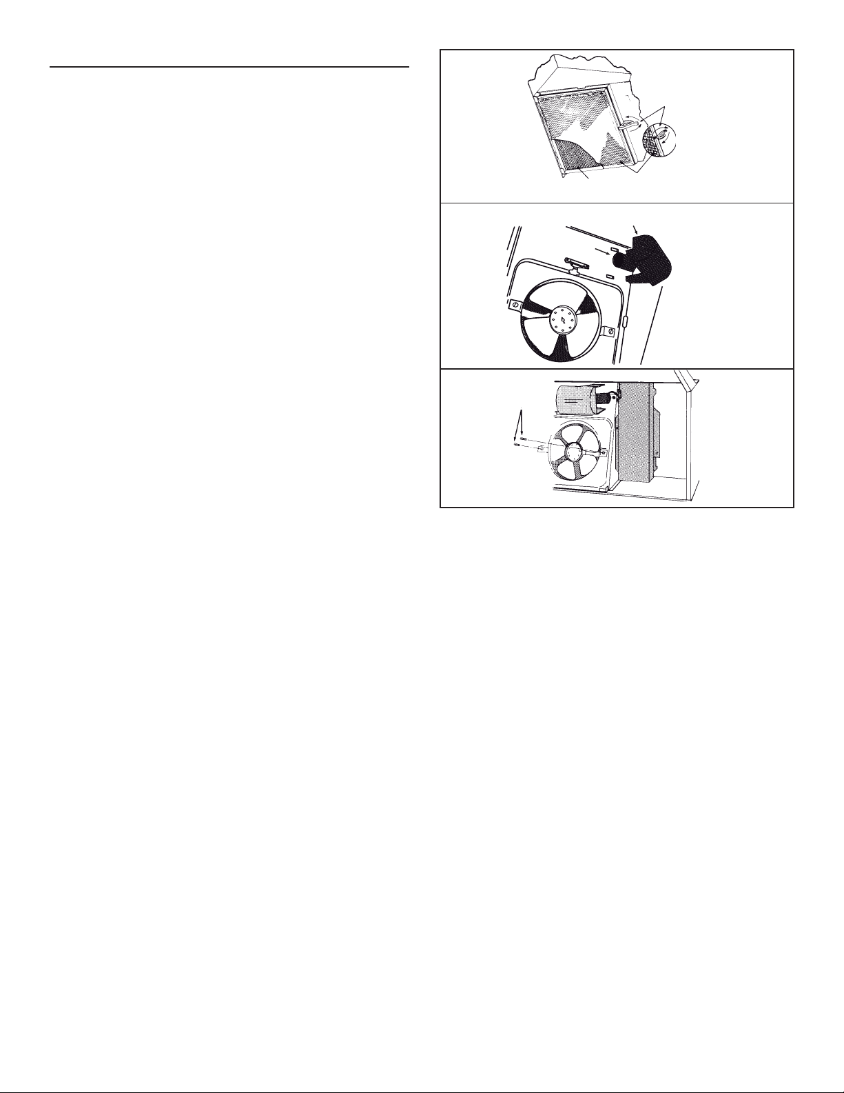
FILTER REMOVAL
Remove filter by turning filter clip to the side and lifting filter out. In ducted
version, turn filter retaining clip to one side and place aluminum filter over
embossed retaining tabs on back of fan housing. Turn filter clip so that the
low end of clip holds single filter firmly in place. (FIG. 13)
In non-ducted version, place non-ducted filter (non-ducted filter to be
purchase separately, model 41F) over tabs on back of fan housing. Turn
filter retaining clip so that high end holds filter firmly in place. Make sure
blue side of non-ducted filter is next to fan blade.
NOTE: Make sure that arrows on filter retaining clip point toward back and
front of hood.
LIGHT BULB REPLACEMENT
Light bulb (not supplied with hood) should be A19 type, E26 base,
75 watts maximum. The lens covering bulb is removed by pressing the
two extending tabs together until they release from the retaining slots.
(FIG. 14)
FAN ASSEMBLY REMOVAL
Be sure power is disconnected. Remove filter. Remove both screws holding
the motor bracket to the range hood and unplug the fan assembly. Be
careful not to allow fan assembly to drop when the screws are removed.
(FIG. 15).
FIG. 13
FIG. 14
FIG. 15
SCREWS
NON-DUCTED FILTER
(SOLD SEPARATELY)
SOCKET
FILTER RETAINING CLIP
ALUMINUM FILTER
LIGHT LENS
- 5 -
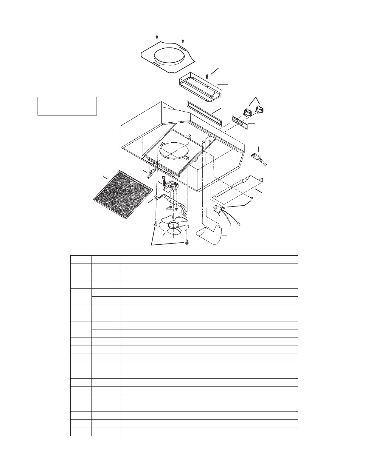
SERVICE PARTS
BU2 SERIES RANGE HOOD
Replacement parts can be
ordered by calling
877-896-1119
B
C
D
E
F
G
H
R
S
Q
I
P
O
J
K
M
L
N
KEY NO.PART NO.DESCRIPTION
1 SR680508 7" ROUND DUCTPLATE (OPTIONAL, PURCHASE SEPARATELY)
2 S99150415 NO. 8B X 1/4" HEX HEAD SHEET METAL SCREWS* (2 REQUIRED)
3 S97005544 DAMPER ASSEMBLY
S97016970 MOTOR AND LIGHT ROCKER SWITCHES, BLACK
4
S97016971 MOTOR AND LIGHT ROCKER SWITCHES, WHITE
S99091022 GRILLE COVER, BLACK
5
S99091020 GRILLE COVER, WHITE
S97010709 BROAN NAMEPLATE (BLACK)
6
S99090881 B
7 S97005678 MOTOR RECEPTACLE WITH WIRES
8 S98006621 OUTLET BOX COVER
9 S99170245 NO. 8 X 3/8" SHEET METAL SCREW*
10 S99270987 BULB HOLDER WITH WIRES
11 S99110437 LIGHT LENS
12 S99020272 FAN BLADE
13 S97011217 SCREW/NUT KIT (INCLUDES 2 NO. 10-16 X .500 SCREWS AND 2 NO. 10-16 SHEET METAL NUTS)
14 S99260428 LOCKING NUTS NO. 6-32* (2 REQUIRED)
15 S98005568 MOTOR MOUNTING BRACKET
16 S97012248 MOTOR ASSEMBLY (INCLUDES KEYS 12, 14 AND 15)
17 S99420472 FILTER RETAINER
18 S97006931 ALUMINUM FILTER
ROAN NAMEPLATE (WHITE)
Order service parts by PART NO. - NOT by KEY No.
* Standard hardaware, may be purchase locally.
- 6 -

Warranty Period and Exclusions: Venmar Ventilation ULC (the “Company”) warrants to the original consumer purchaser of its product (“you”) that the
Limited Warranty
product (the “Product”) will be free from material defects in the Product or its workmanship for a period of one (1) year from the date of original purchase (or
such longer period as may be required by applicable law).
The limited warranty period for any replacement parts provided by the Company and for any Products repaired or replaced under this limited warranty shall
be the remainder of the original warranty period (or such longer period as may be required by applicable law).
This warranty does not cover fluorescent lamp starters, tubes, halogen and incandescent bulbs, fuses, filters, ducts, roof caps, wall caps and other
accessories for ducting that may be purchased separately and installed with the Product. This warranty also does not cover (a) normal maintenance and
service, (b) normal wear and tear, (c) any Products or parts which have been subject to misuse, abuse, abnormal usage, negligence, accident, improper
or insufficient maintenance, storage or repair (other than repair by the Company), (d) damage caused by faulty installation, or installation or use contrary to
recommendations or instructions, (e) any Product that has been moved from its original point of installation, (f) damage caused by environmental or natural
elements, (g) damage in transit, (h) natural wear of finish, (i) Products in commercial or nonresidential use, or (j) damage caused by fire, flood or other act
of God or (k) Products with altered, defaced or removed serial numbers. This warranty covers only Products sold to original consumers in Canada by the
Company or its Canadian distributors authorized by the Company.
This warranty supersedes all prior warranties and, subject to applicable law, is not transferable from the original consumer purchaser.
No Other Warranties: This Limited Warranty contains the Company’s sole obligation and your sole remedy for defective products. The foregoing warranties
are exclusive and in lieu of any other warranties and conditions, express or implied. THE COMPANY DISCLAIMS AND EXCLUDES ALL OTHER EXPRESS
WARRANTIES AND CONDITIONS, AND DISCLAIMS AND EXCLUDES ALL WARRANTIES AND CONDITIONS IMPLIED BY LAW, INCLUDING
WITHOUT LIMITATION THOSE OF MERCHANTABILITY AND FITNESS FOR A PARTICULAR PURPOSE. To the extent that applicable law prohibits the
exclusion of implied warranties or conditions, the duration of any applicable implied warranty or condition is limited to the period specified for the express
warranty above. Some jurisdictions do not allow limitations on how long an implied warranty lasts, so the above limitation may not apply to you. Any oral or
written description of the Product is for the sole purpose of identifying it and shall not be construed as an express warranty.
Whenever possible, each provision of this Limited Warranty shall be interpreted in such manner as to be effective and valid under applicable law, but if
any provision is held to be prohibited or invalid, such provision shall be ineffective only to the extent of such prohibition or invalidity, without invalidating the
remainder of such provision or the other remaining provisions of the Limited Warranty.
Remedy: During the applicable limited warranty period, the Company will, at its option, provide replacement parts for, or repair or replace, without charge,
any Product or part thereof, to the extent the Company finds it to be covered by and in breach of this limited warranty under normal use and service. The
Company will ship the repaired or replaced Product or replacement parts to you at no charge. You are responsible for all costs for removal, reinstallation
and shipping, insurance or other freight charges incurred in the shipment of the Product or part to the Company. If you must send the Product or part to the
Company, as instructed by the Company, you must properly pack the Product or part—the Company is not responsible for damage in transit. The Company
reserves the right to utilize reconditioned, refurbished, repaired or remanufactured Products or parts in the warranty repair or replacement process. Such
Products and parts will be comparable in function and performance to an original Product or part and warranted for the remainder of the original warranty
period (or such longer period as may be required by applicable law).
Company reserves the right, in its sole discretion, to refund the money actually paid by you for the Product in lieu of repair or replacement. If the Product
or component is no longer available, replacement may be made with a similar product of equal or greater value, at Company’s sole discretion. This is your
sole and exclusive remedy for breach of this limited warranty.
Exclusion of Damages: THE COMPANY’S OBLIGATION TO PROVIDE REPLACEMENT PARTS, OR REPAIR, REPLACE OR REFUND, AT THE
COMPANY’S OPTION, SHALL BE YOUR SOLE AND EXCLUSIVE REMEDY UNDER THIS LIMITED WARRANTY AND THE COMPANY’S SOLE AND
EXCLUSIVE OBLIGATION. THE COMPANY SHALL NOT BE LIABLE FOR INCIDENTAL, INDIRECT, CONSEQUENTIAL OR SPECIAL DAMAGES
ARISING OUT OF OR IN CONNECTION WITH THE PRODUCT, ITS USE OR PERFORMANCE. Incidental damages include but are not limited to such
damages as loss of time and loss of use. Consequential damages include but are not limited to the cost of repairing or replacing other property which was
damaged if the Product does not work properly.
THE COMPANY SHALL NOT BE LIABLE TO YOU, OR TO ANYONE CLAIMING UNDER YOU, FOR ANY OTHER OBLIGATIONS OR LIABILITIES,
INCLUDING, BUT NOT LIMITED TO, OBLIGATIONS OR LIABILITIES ARISING OUT OF BREACH OF CONTRACT OR WARRANTY, NEGLIGENCE
OR OTHER TORT OR ANY THEORY OF STRICT LIABILITY, WITH RESPECT TO THE PRODUCT OR THE COMPANY’S ACTS OR OMISSIONS OR
OTHERWISE.
Some jurisdictions do not allow the exclusion or limitation of incidental or consequential damages, so the above limitation or exclusion may not apply to you.
This warranty gives you specific legal rights, and you may also have other rights, which vary from jurisdiction to jurisdiction. The disclaimers, exclusions,
and limitations of liability under this warranty will not apply to the extent prohibited by applicable law.
This warranty covers only replacement or repair of defective Products or parts thereof at the Company’s main facility and does not include the cost of field
service travel and living expenses.
Any assistance the Company provides to or procures for you outside the terms, limitations or exclusions of this limited warranty will not constitute a waiver
of such terms, limitations or exclusions, nor will such assistance extend or revive the warranty.
The Company will not reimburse you for any expenses incurred by you in repairing or replacing any defective Product, except for those incurred with the
Company’s prior written permission.
How to Obtain Warranty Service: To qualify for warranty service, you must (a) notify the Company at the address or telephone number stated below within
seven (7) days of discovering the covered defect, (b) give the model number and part identification and (c) describe the nature of any defect in the Product
or part. At the time of requesting warranty service, you must present evidence of the original purchase date. If you cannot provide a copy of the original
written limited warranty, then the terms of the Company’s most current written limited warranty for your particular product will control. The most current
limited written warranties for the Company’s products can be found at www.broan.ca
Venmar Ventilation ULC, 550 Lemire Blvd., Drummondville, Québec, Canada J2C 7W9
www.broan.ca 1-877-896-1119
- 7 -
 Loading...