

INSTALLATION AND USER GUIDE
CENTRAL VACUUM POWER UNITS
!
FOR RESIDENTIAL USE ONLY
!
BQ550 / BQ650 / BQ700 / BQ500KIT
AB0039
MODELS SFDB-DH, SFDB-DI, SFDB-DJ AND SFDB-DT
VENMAR VENTILATION ULC WWW.BROAN.CA 1-877-896-1119
EGISTER YOUR PRODUCT ONLINE AT : WWW.BROAN.CA
R
24007 rev. A

IMPORTANT SAFETY INSTRUCTIONS
SAVE THESE INSTRUCTIONS
READ ALL INSTRUCTIONS BEFORE USING THIS APPLIANCE
When using an electrical appliance, basic precautions should always be followed, including the following:
WARNING
To reduce the risk of fire, electric shock or injury:
1. Do not use on wet surfaces or outdoors.
2. Do not vacuum liquids or fine powders (such as
drywall dust).
3. Do not use to pick up flammable or combustible
liquids such as gasoline or use in areas where they
may be present.
4. Do not pick up anything that is burning or smoking,
such as cigarettes, matches, or hot ashes.
5. Do not allow to be used as a toy. Close attention is
necessary when used by or near children.
6. Use only as described in this manual. Use only
manufacturer's recommended attachments.
7. Keep hair, loose clothing, fingers and all parts of
body away from openings and moving parts.
8. Turn off all controls before unplugging.
9. Use extra care when cleaning on stairs.
10. Do not handle plug or appliance with wet hands.
11. Do not use with damaged cord or plug. If appliance
is not working as it should, if it has been dropped,
damaged, left outdoors, or dropped into water, return
it to a Service Center.
12. Keep your work area well lighted.
13. Connect to a properly grounded outlet only. See
grounding instructions shown on page 9.
14. When performing installation, servicing or cleaning
the unit, it is recommended to wear safety glasses
and gloves.
15. When applicable local regulations comprise
more restrictive installation and/or certification
requirements, the aforementioned requirements
prevail on those of this document and the installer
agrees to conform to these at his own expenses.
!
CAUTION
1. Do not put any object into openings. Do not use with
any opening blocked; keep free of dust, lint, hair and
anything that may reduce air flow.
2. Ensure air flows freely and exhausts unobstructed
from top or side outlet.
3. Do not use without filter (or filters, according to the
model) in place.
4. Do not use to blow leaves or debris.
5. Do not place any object on top of the unit.
6. Do not install the unit horizontally.
7. Do not use the pail as a wash bucket.
8. Do not use the pail as a stool.
9. Avoid picking up sharp objects.
10. This appliance is for use on a standard 120 VAC,
dedicated 15-amp branch circuit. Some brands of
house panel breakers may be more sensitive to
startup current than others (for example, Square
D brand). In the event where nuisance tripping of
the house panel breaker occurs*, we recommend
changing the breaker with an “HM” type of the same
AMP rating.
*after ensuring that the circuit is DEDICATED to the
central vacuum unit, meaning that there is no other
electrical device connected to the central vacuum
unit circuit.
11. Do not unplug the unit by pulling on cord. To unplug,
grasp the plug, not the cord.
12. Store your vacuum cleaner indoors in a clean, dry
area, and away from extreme temperatures.
13. Any servicing other than that recommended in
this manual should be performed by an authorized
service facility.
14. We recommend that your unit be inspected by a
specialized technician once a year.
2

TABLE OF CONTENTS
GENERAL INFORMATION .........................................................................................................4
TOOL LISTING .......................................................................................................................................................4
WORKING WITH PLASTIC TUBING......................................................................................................................4
C
UTTING TUBING ......................................................................................................................................................4
MAKING A JOINT ......................................................................................................................................................4
CEMENTING FLEXIBLE TUBING .....................................................................................................................................4
SECURE WIRE TO TUBING ..........................................................................................................................................4
WALL INLET INSTALLATION ....................................................................................................4
MAKING THE WALL INLET CUTOUT ................................................................................................................................4
ATTACHING THE INLET MOUNTING PLATE (V144) ............................................................................................................4
COMPLETING THE INLET ASSEMBLY ..............................................................................................................................4
INSTALLING THE INLET (V111) .................................................................................................................................... 4
V800W CANSWEEP® UNDER CABINET INSTALLATION .................................................... 5-6
V800W CANSWEEP® BASEBOARD WALL INSTALLATION ....................................................7
POWER UNIT INSTALLATION ...................................................................................................8
LOCATING THE POWER UNIT ..............................................................................................................................8
CHANGING INTAKE LINE DIRECTION .................................................................................................................8
MOUNTING THE POWER UNIT ............................................................................................................................9
FITTING MAIN LINE TO POWER UNIT ...............................................................................................................10
GROUNDING INSTRUCTIONS ................................................................................................10
WIRING ................................................................................................................................................................10
OPERATION AND MAINTENANCE .........................................................................................11
WHEN TO CHANGE BAG* OR EMPTY DEBRIS PAIL ........................................................................................ 11
HOW TO EMPTY DEBRIS PAIL (BQ650 AND BQ700 POWER UNITS ONLY) ................................................... 11
BQ550 AND BQ500KIT POWER UNITS DETAILED VIEW .................................................................................. 11
DISPOSABLE BAG REPLACEMENT (BQ550 AND BQ500KIT POWER UNITS ONLY) ..................................... 11
PERMANENT FILTER (BQ650 AND BQ700 POWER UNITS ONLY) ..................................................................12
REMOVAL AND INSTALLATION OF PERMANENT FILTER (BQ650 AND BQ700 POWER UNITS ONLY) ........ 12
MOTOR FOAM FILTER (ALL UNITS) ..................................................................................................................12
REMOVING MOTOR FOAM FILTER ................................................................................................................................12
REINSTALLING MOTOR FOAM FILTER ............................................................................................................................ 12
ACCESSORIES (BQ500KIT ONLY) .........................................................................................13
ACCESSORIES INCLUDED ................................................................................................................................13
INSTALLING HOSE HANGER .............................................................................................................................13
TROUBLESHOOTING GUIDE ..................................................................................................14
SERVICE PARTS ......................................................................................................................15
WARRANTY ..............................................................................................................................16
3
GENERAL INFORMATION WALL INLET INSTALLATION
TOOL LISTING
Depending on the installation, the use of the following tools
may be required:
Wire strippers, 1/4’’ and 1/2” drill bits, utility knife, putty knife,
2½’’ hole saw, keyhole saw, hammer, cold chisel, level,
flashlight, drill, electrical tape, Phillips no. 2 screwdriver,
wrench, hacksaw, tape measure, safety glasses.
Power tools are recommended to make the installation proceed
quickly. A mask and gloves should be worn when cutting
ducting and using glue.
WORKING WITH PLASTIC TUBING
CUTTING TUBING
Measure the length of tube needed. Allow 5/8” of tubing for
inserting into fittings and 1½” for placing into flexible tubing.
Cut the plastic tubing with a hacksaw, ensuring that the cut
is exactly square. Use wire cutters or tin snips to cut flexible
tubing, 8” lengths of flexible tubing should not be cut.
Use a small knife or steel wool to remove any burrs from the
inside of the tube.
Use a file to slightly bevel the outside of the tube so that it will
easily slide into the fitting. Use steel wool or a light grained
sandpaper to buff the surface of the tube which will be glued.
MAKING A JOINT
Insert the tube into the fitting,
aligning both parts as they will be
installed. Mark the tube and the
fitting to quickly realign the joint.
Apply cement in an inch-wide
band to the outside of the tube.
Insert the tube into the fitting with
the alignment marks a quarter
turn apart, and then quickly push
and turn the fitting to align the
marks and spread the cement.
Allow 1 minute for the joint to dry.
CEMENTING FLEXIBLE TUBING
Ensure the ends of the flexible tubing are even. When joining
flexible tubing to plastic tubing or to an inlet mounting plate,
apply cement to both the inside of the flexible tubing and the
outside of the plastic tubing or mounting plate tubing ring. Twist
both pieces while joining them to evenly spread the glue. Allow
5 minutes for the cement to set in flexible tubing.
SECURE WIRE TO
TUBING
The low-voltage power wiring is
run along with the tubing. Use
electrical tape to secure the
wire to the tubing. Tape the wire
approximately every 12" to 18".
AO0010
AO0011
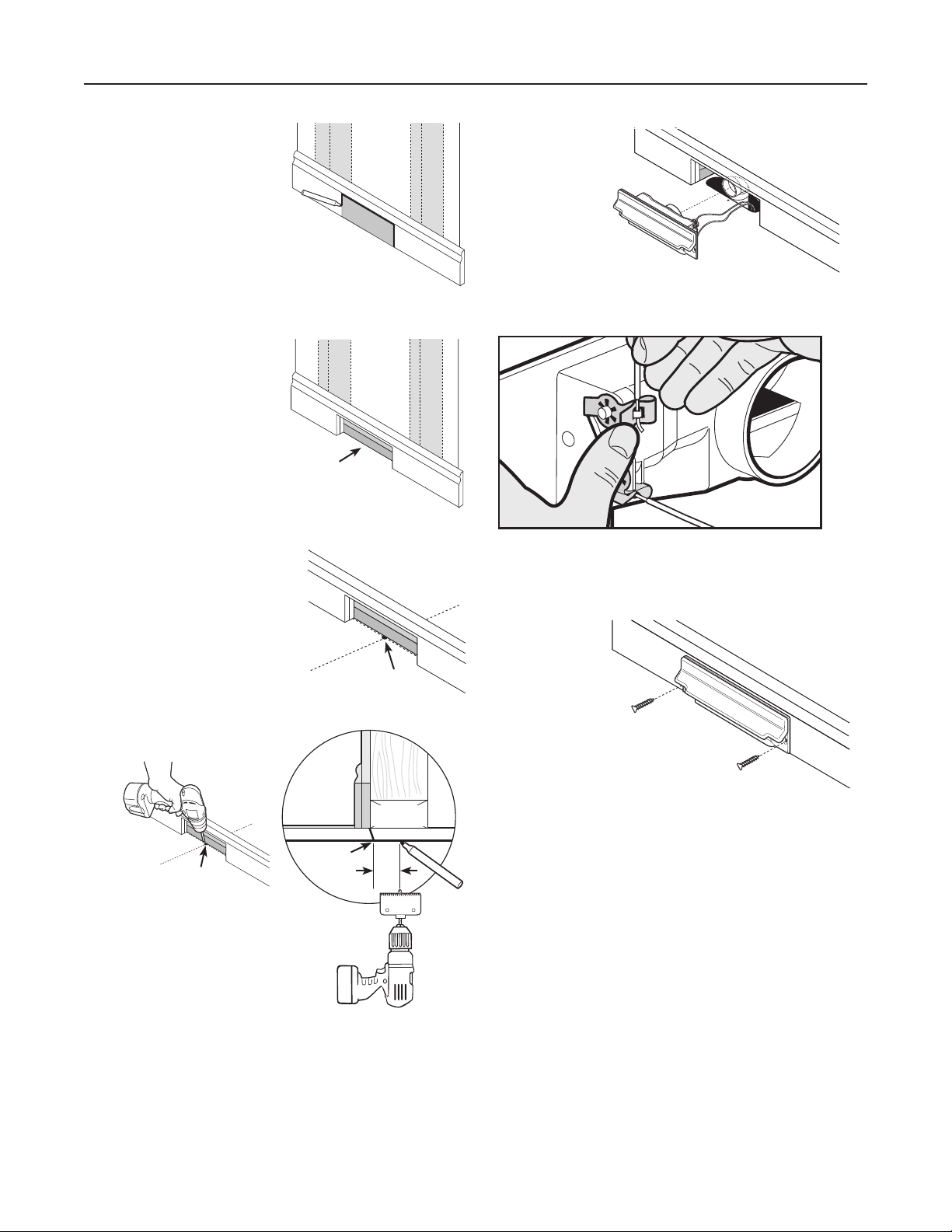
MAKING THE WALL INLET CUTOUT
The wall inlet should be located 18” on-center from the floor
and directly in line with the attic or basement inlet tubing hole
previously drilled in the wall plate or header. The wall inlet
cutout must be exactly 3
7
∕8” high by 27∕8” wide.
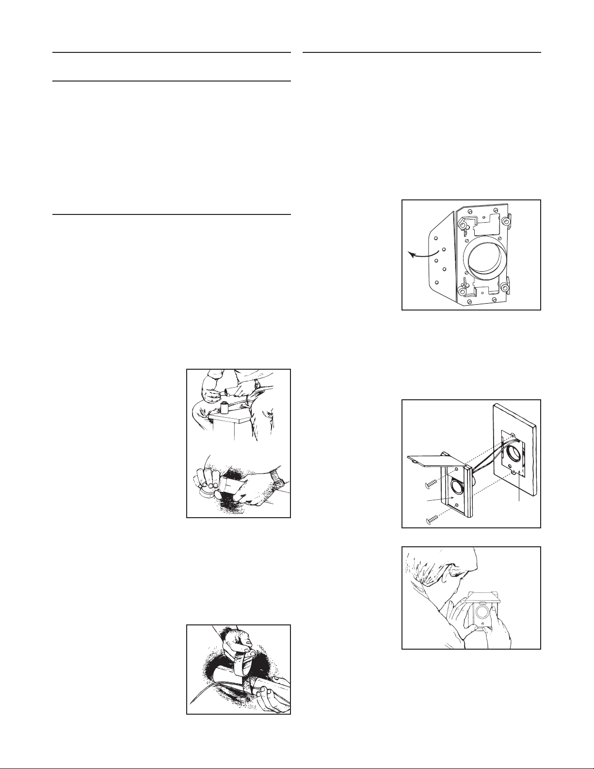
ATTACHING THE INLET MOUNTING PLATE
(V144)
Reach through the inlet hole and locate the inlet tubing. Pull
the flexible tubing through the inlet hole and remove the
low-voltage wiring from inside the tube.
Remove the nail flange
from the inlet mounting
plate (see illustration at
right). Apply cement to
both the inside of the
flexible tubing and to the
outside of the mounting
plate’s tube ring. Insert
the mounting plate’s
tube ring in the flexible
tubing and twisting the
pieces as you join them to spread the cement, and align the
mounting plate in a vertical position.
Now, strip the ends of the two low-voltage wires, and then
connect the wires to the screw terminals on the back of the
inlet cover. When the wiring is complete, assemble the inlet
cover to the tube guard and mounting plate.
AR0040
COMPLETING
THE INLET
ASSEMBLY
Once you have attached
the mounting plate to the
flexible tubing, pull the
low-voltage wire through
the top wiring hole in the
mounting plate.
INLET
AE0024A
MOUNTING
PLATE
INSTALLING THE
INLET (V111)
Place the inlet into the
wall cutout (the inlet
cover remains on the
outside). Hold the inlet
in place and gradually
tighten down each screw
a little bit at a time.
AO0045
4
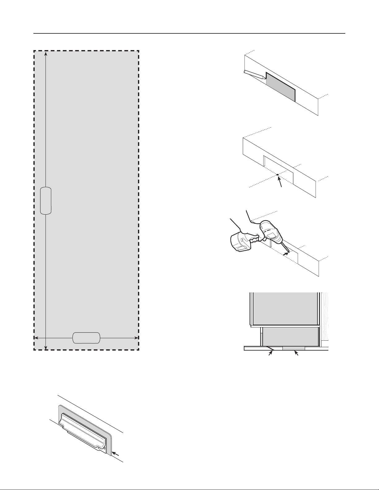
V800W CANSWEEP® UNDER CABINET INSTALLATION
Align the template
®
(cut from this
instruction sheet)
onto the kick plate to
the desired location,
and trace the outline
of the area.
Template
Cut out the desired
opening and
discretely mark the
center of the
opening on the floor.
Mark Center
6¾"
TEMPLATE
V800W CANSWEEP
2⅜"
If by any chance the opening was cut too big,
a trim plate (part number V801W) is available
to provide a perfect cover.
Drill a small
reference hole
along the
center line
behind the
kick plate
through the
subfloor.
Locate the
reference hole from
beneath the
subfloor. Cut a
4” x 4” access hole
on your chosen
position along the
center line under
the kick space.
Kick Plate
Opening
Reference
Cabinet Space
Hole
Kick Space
4" x 4" Access
Hole
Trim plate
5
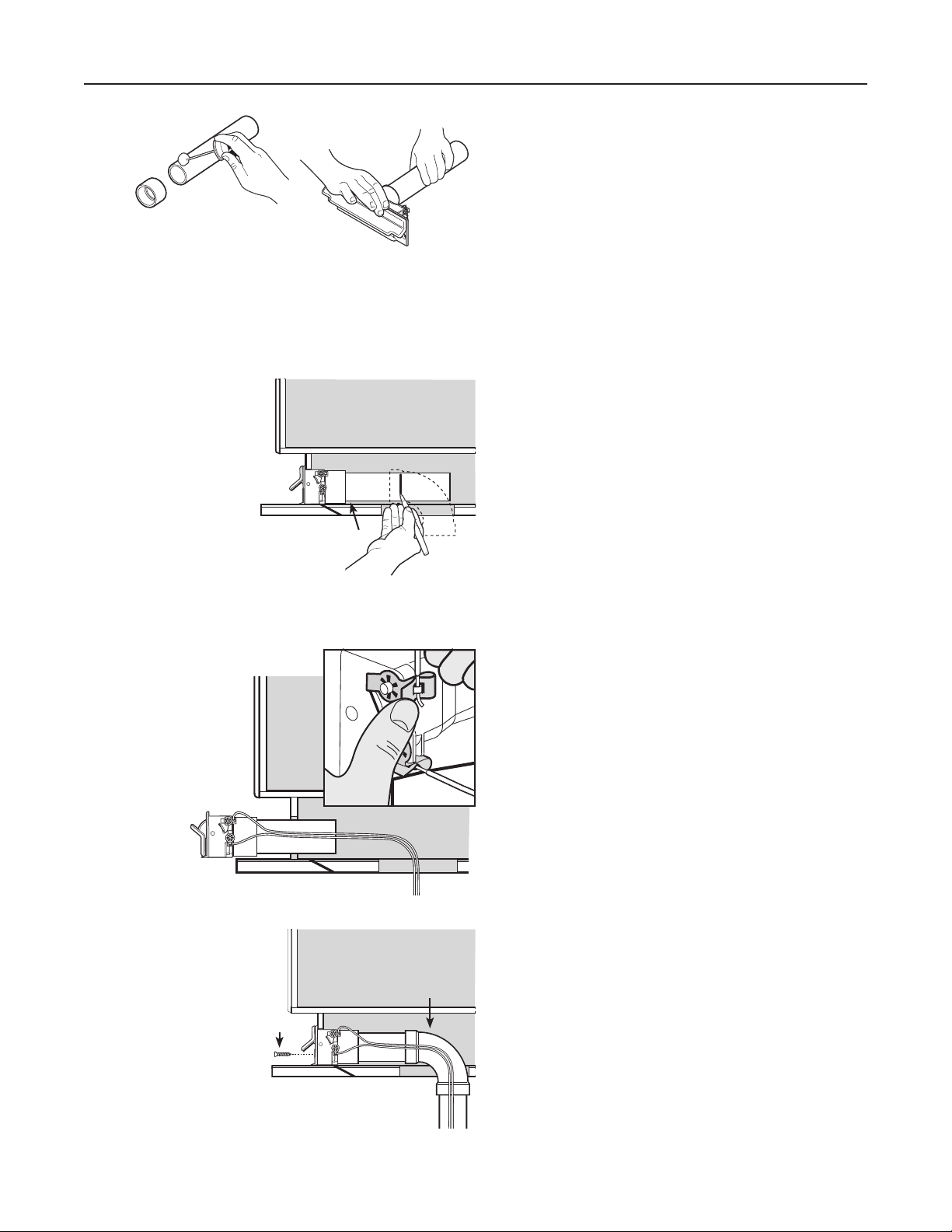
V800W CANSWEEP® UNDER CABINET INSTALLATION (CONT'D)
Fig. A
Fig. B
Solvent weld a coupling
to a piece of 2” central
vacuum pipe, long enough
to reach the 4” x 4” access
hole from the opening on
the kick plate (Fig. A).
Friction fit the other end
of the coupling to the
CanSweep® until secure.
Do not glue, friction fit only
(Fig. B).
Insert the
CanSweep®/pipe
into the opening on
the kick plate.
Use a 90° sweep
elbow fitting to
determine a cut
mark on the other
end of the pipe.
Then cut the pipe
at the mark.
Slide the
low voltage wires
into the
CanSweep® clips
as shown to
complete the wiring
connections.
Slide the
CanSweep®/pipe
and low voltage
wires into the
opening on
the kick plate. Glue
both ends of the
elbow to the piping
system, and then
secure the
CanSweep® to the kick plate with the 2 supplied screws.
Screws
Glue elbow
to pipe
6
V800W CANSWEEP® BASEBOARD WALL INSTALLATION
Do not glue
Choose a desired
position on the baseboard
between two studs.
Place the template (cut
from this instruction sheet)
on the position, and trace
the outline of the area.
Template
Make piping
connections as
required and
ready the short
90° elbow in position
behind the CanSweep®.
Make sure that the opening of the elbow will securely
attach onto the spigot on the back of the CanSweep®
when it is time for connection.
CanSweep® to
the elbow.
Attach wires
Trim the opening on
the baseboard and
through the drywall
until reaching the
2" x 4" bottom wall
plate.
2" x 4" Bottom Plate
Against the edge of the
2" x 4" bottom plate, mark the
center of the opening.
Mark Center
Reference
Reference Hole
Drill a small reference hole
at the mark through the subfloor to below.
Locate the reference hole from below
and measure back 1
to remove the 2"x4" bottom plate
section behind the opening.
7
/8”. Use a 2” hole saw
Hole
2" x 4"
Bottom Plate
1⅞"
Slide the low volt wires into the CanSweep® clips
as shown to complete the wiring connections.
Slide the
CanSweep® and
low voltage wires
into the opening
on the
baseboard.
Friction fit the
CanSweep®
spigot into the elbow. Secure the CanSweep® to the
baseboard with the 2 supplied screws.
7
POWER UNIT INSTALLATION
!
WARNING
Do not install outdoors. Before hanging the unit,
rest it on a leveled surface to prevent it from falling
down. When performing installation, servicing or
cleaning the unit, it is recommended to wear safety
glasses and gloves.
LOCATING THE POWER UNIT
• Locate the power unit away from the general living area in
an accessible location for cleaning and maintenance.
• Locate the power unit within 6 feet of a grounded electrical
outlet. The power unit requires a 120 VAC power source,
dedicated 15-amp branch circuit.
• Do not locate the power unit close to a source of extreme
heat (i.e.: water heater) or in an area with a high ambient
temperature (i.e.: attic, furnace room).
• If the power unit is located in a closet or a small utility
room, make sure the area is well-ventilated (e.g.: with door
louvers).
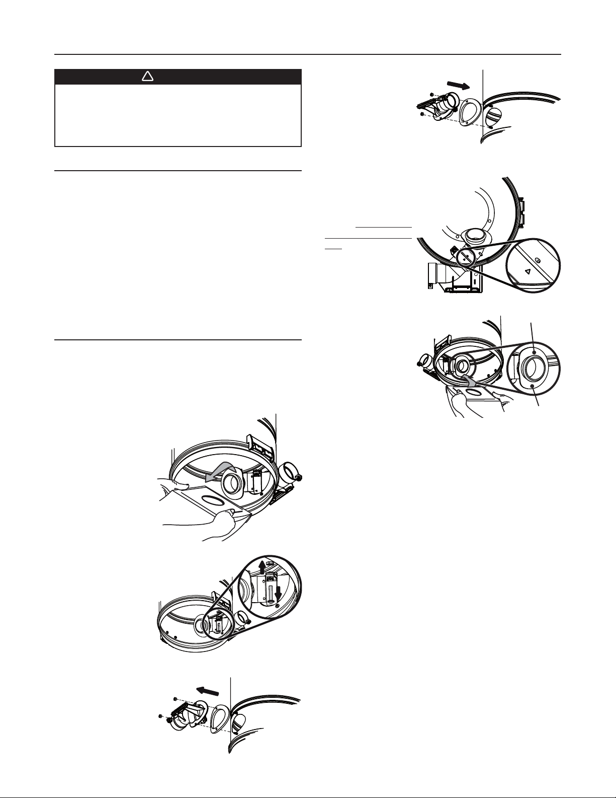
CHANGING INTAKE LINE
DIRECTION
The intake line connects to the right side of the unit. However,
it is possible to change this configuration; to connect the intake
line to the left side of the unit, follow these steps:
Remove debris pail from power unit by releasing both latches
on sides of the unit, pulling them out and then pushing up.
Detach the pail from unit.
BQ550 AND BQ500KIT
BQ550 and
BQ500KIT: Grasp
the edges of the bag
collar and pull down;
the bag will slide off
easily. Do not pull on
the bag. Set the bag
aside.
AO0078
All units: Flip the
intake elbow 180°,
then reassemble it to
the unit, taking care to
keep its gasket at its
original position.
NOTE: Ensure the
gasket is not folded in
order to prevent lack of suction and noise.
AD0077
BQ550 AND
BQ550 and BQ500KIT:
Reassemble the bag
adapter to the intake
elbow. Align triangle
with small inclined
stud, then tighten
the junction using
the screw and nut
previously removed
in
.
BQ550 and BQ500KIT:
Put the bag back in
place by grasping the
edges of its collar
and insert over bag
adapter. Be careful
not to tear the bag.
Ensure the collar is
positioned between
the taper ring and the
bag stopper on the bag adapter.
BQ500KIT
AD0078
BQ550 AND
BQ500KIT
AO0080
All units: Put the pail back in its place.
TAPER RING
BAG STOPPER
BQ550 and
BQ550 AND BQ500KIT
BQ500KIT: Using a
Phillips screwdriver
no. 2, remove the
screw tightening the
bag adapter and
intake elbow junction.
Disassemble the
bag adapter from the
intake elbow and set aside with its screw and nut.
AD0075
All units: Disassemble
the intake elbow from
the back of the unit
using a 3/8” socket to
remove both retaining
nuts and screws.
AD0076
8
POWER UNIT INSTALLATION (CONT'D)
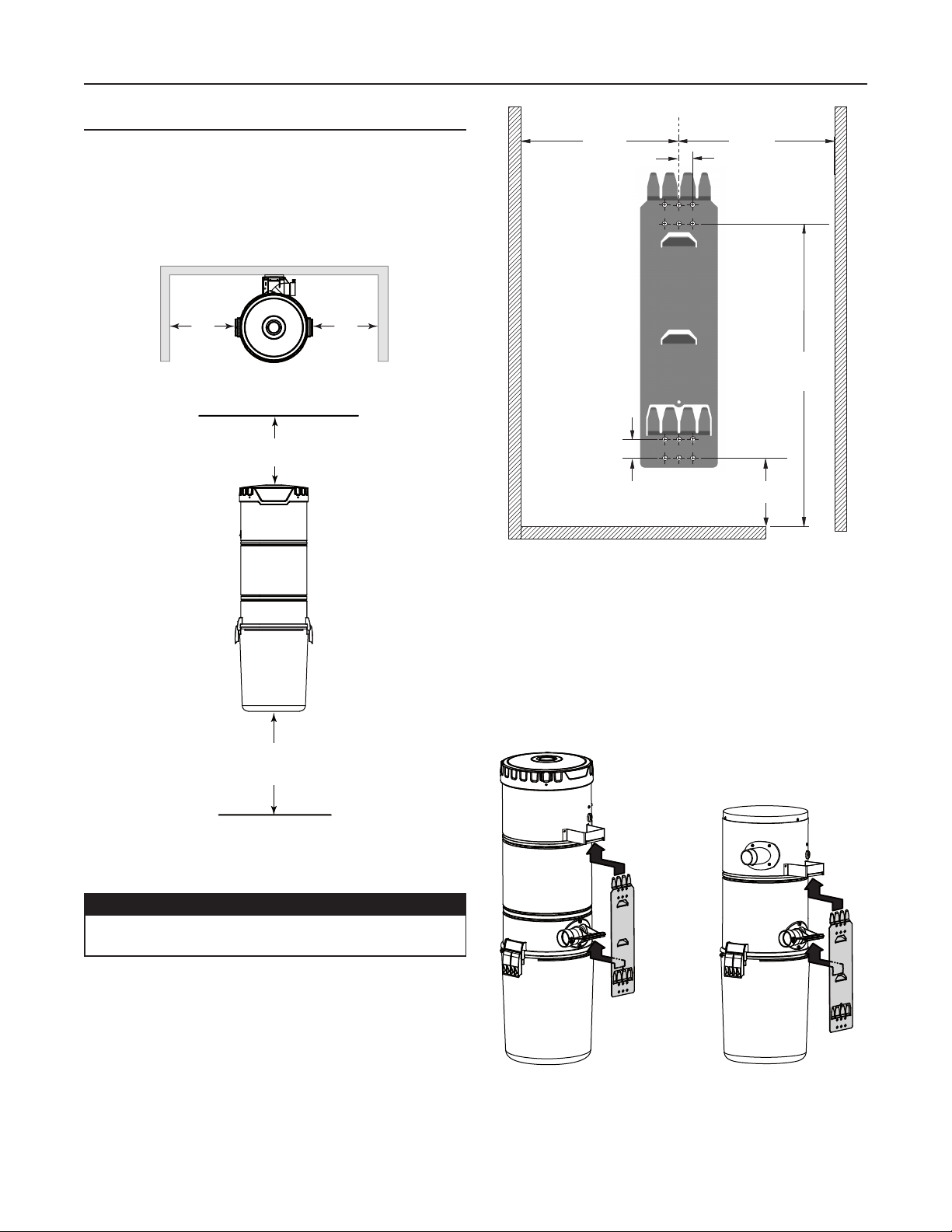
MOUNTING THE POWER UNIT
Carefully remove debris pail from power unit. Make sure
the bag is properly installed in power unit (BQ550 and
BQ500KIT units). Remove the installation kit and securely
reinstall debris pail.
Refer to illustration below to maintain minimum walls and
floor clearance dimensions.
MINIMUM CLEARANCE DIMENSIONS
TOP VIEW
12”
minimum
12” minimum
from ceiling
12”
minimum
FRONT VIEW
C
AD0079A
UPPER
MOUNTING
HOLES
LOWER
MOUNTING
HOLES
L
1” TYP.
18 ¹/
3/4” TYP.
32
8”18 ¹/ 8”
7
45¼”
MIN.
HEIGHT
/8”
Use the provided mounting screws to secure the mounting
bracket on the wall through upper and lower mounting
holes.
Hang power unit onto wall mounting bracket. Ensure
the back brackets of the power unit are engaged with
corresponding wall bracket fingers (or top fingers and lower
tab for BQ550 and BQ500KIT models; see figure below).
Pull the power unit down to secure.
18” minimum
above floor
AD0039A
Position and install the wall mounting bracket with the
provided screws. Refer to illustration in the right column for
proper mounting dimensions.
CAUTION
Make sure to screw the wall mounting bracket
directly to a wall stud for a solid installation.
BQ650 AND BQ700
BQ550 AND BQ500KIT
AD0074
9
POWER UNIT INSTALLATION
!
(
CONT'D)
GROUNDING
INSTRUCTIONS
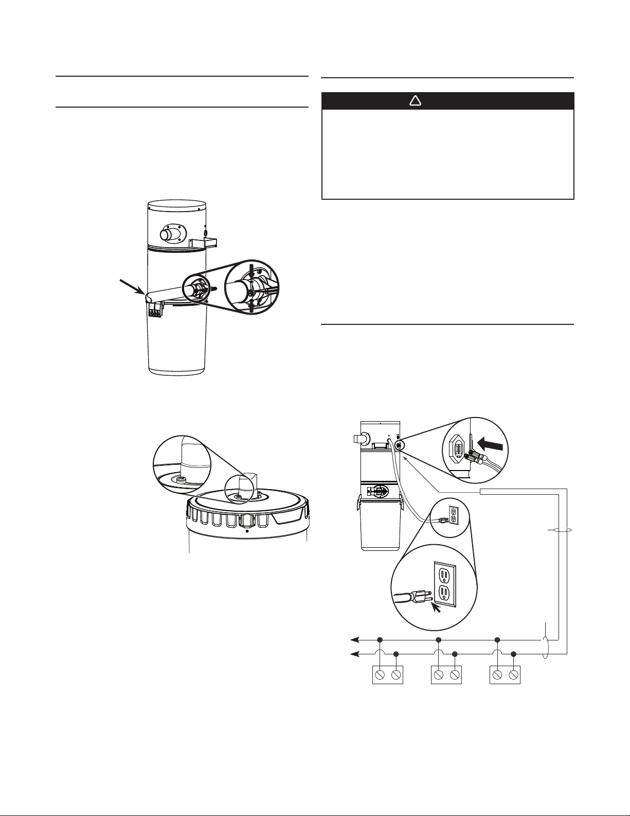
FITTING MAIN LINE TO POWER UNIT
Run house vacuum line up to the elbow behind the power
unit. Insert the end of the line in the elbow opening and
secure house vacuum line by hand tightening the screw
and nut provided (see illustration below) DO NOT GLUE.
INTAKE LINE TYPICAL CONNECTION
TO POWER UNIT
SCREW AND
NUT FROM
PAR TS BAG
INTAKE LINE
AJ0001
Assemble exhaust tubing to exhaust outlet on top or top
side of the unit, according to the power unit model. DO NOT
GLUE.
NOTE FOR BQ700 UNIT ONLY
If desired, the
coupling or elbow
used to connect
the exhaust line to
the top of the unit
may be secured
using two 5/8”
included screws.
See illustration at
right.
AJ0003
Make sure all
tubing connections are air tight.
The exhaust should not be vented into a wall, ceiling or
concealed space in the house. It is recommended to vent
the vacuum exhaust air to the outdoors. Exterior vented
exhaust line should end using Model V145 wall cap.
NOTE: For optimal indoor air quality, exhausting the power
unit to the outdoors is recommended but is not
required.
WARNING
Improper connection of the equipment-grounding
conductor can result in a risk of electric shock.
Check with a qualified electrician or service person
if you are in doubt as to whether the outlet is
properly grounded. Do not modify the plug provided
with the appliance – if it will not fit the outlet, have
a proper outlet installed by a qualified electrician.
Grounding Instructions – This appliance must be grounded.
If it should malfunction or break down, grounding provides a
path of least resistance for electric current, to reduce the risk
of electric shock. This appliance is equipped with a cord having
an equipment-grounding conductor and grounding plug. The
plug must be plugged into an appropriate outlet that is properly
installed and grounded in accordance with all local codes and
ordinances.
WIRING
This appliance is for use on a standard 120 VAC, dedicated
15-amp branch circuit with a NEMA 5-15R receptacle. Make
sure that the power unit is connected to an outlet and has a
grounding attachment plug that looks like the plug shown in
illustration below. No adapter should be used with this power
unit.
CRIMP
CONNECTORS TO
BE CONNECTED
IN LOW VO LTAG E
TABS
GROUNDED OUTLETS
INLET LEADS
GROUNDING PIN
TO
OTHER
INLETS
MODEL V133 (22/2)
LOW VO LTAG E WIRE
AE0044
INLET
NOTE: Inlet leads to be connected to power unit low voltage
tabs using crimp connectors (included in parts bag)
and low voltage harness.
10
INLET INLET

OPERATION AND MAINTENANCE
Open the wall inlet cover and insert the end of the hose into the
inlet to turn on the vacuum.
For non-switched hoses, inserting the hose automatically turns
on the power unit; removing the hose shuts off the power unit.
Some hoses have switches which can be used to activate
power unit. The ON/OFF switch located on the power unit
needs to be kept in the OFF position.
As you vacuum, dirt and dust are carried to the power unit
where they remain in a bag or in the debris pail (according to
the power unit model).
Use the cleaning tools as you would for any other vacuum
cleaner. Avoid picking up very large debris or lengthy as these
kinds of objects may become lodged in the hose or tubing.
WHEN TO CHANGE BAG* OR EMPTY
DEBRIS PAIL
With a 6 U.S. gallons (22.7 liters) capacity, under normal
conditions the bag/debris pail requires changing/emptying
approximately twice a year. If the bag/debris pail is full, you will
notice a reduced suction from the system. Unless this loss of
suction is caused by a blockage in the system, changing the
bag or emptying the debris pail will solve the problem.
NOTE: Even if not filled to capacity, if the bag seems tightly
stretched when removing the debris pail, changing
the bag will prevent it from tearing.
* Only BQ550 and BQ500KIT units are equipped with a
disposable bag (391C).
HOW TO EMPTY DEBRIS PAIL
(BQ650 AND BQ700 POWER UNITS
ONLY)
To empty the debris pail, release both latches on sides of the
unit by pulling out and then pushing up. Holding the pail by the
latches, lower it from unit. Carry pail to trash receptacle and
dispose of debris. Put the pail back in its place.
BQ550 AND BQ500KIT POWER
UNITS DETAILED VIEW
EXHAUST OUTLET
MOTOR FOAM FILTER
VACUUM CHAMBER
DISPOSABLE BAG
AL0009
INLET
BAG ADAPTER
LATCH
D
EBRIS PAIL
DISPOSABLE BAG REPLACEMENT
(BQ550 AND BQ500KIT POWER
UNITS ONLY)
To remove the disposable bag, release both latches on
sides of the unit by pulling out and then pushing up. Remove
the pail from unit. Grasp the edges of the bag collar and pull
down. The bag will slide off easily. Do not pull on the bag.
Unfold the new bag.
Grasp collar where indicated on the new bag and insert over
bag adapter. Be careful not to tear the bag. Ensure the collar
is positioned between the taper ring and the bag stopper on
the bag adapter (see illustration below). Put the pail back in
its place.
TAPER RING
AO0081
11
BAG STOPPER

OPERATION AND MAINTENANCE (CONT'D)
PERMANENT FILTER (BQ650 AND
BQ700 POWER UNITS ONLY)
This filter protects the motor and stops small particles from
escaping to the outside of the power unit wihout the need to
replace it. The filter cleans itself by moving up when the power
unit starts, and dropping down when the unit is turned off.
Under normal use, there is no need to maintenance this filter.
It is possible to remove it to inspect the motor foam filter, or
to replace it if ever it has been damaged (by sharp debris, for
example).
REMOVAL AND INSTALLATION OF
PERMANENT FILTER (BQ650 AND
BQ700 POWER UNITS ONLY)
Remove the pail from unit. To remove the permanent filter,
use pull tab (A) located on edge of filter to pull and loosen
filter from inlet chamber wall. Squeeze from both sides of
the filter to the center of
the housing.Then, carefully
remove it from the unit.
Squeeze the filter in order
to move it past the inlet
opening (B) Let the filter
bear against the unit wall
by releasing the pressure.
Make sure to place the rigid ring in its groove to ensure
proper sealing.
NOTE: Make sure the filter
is installed so that
the pull tab (A)
is accessible for
future filter removal.
AD0084
AD0085
A
B
MOTOR FOAM FILTER (ALL UNITS)
A motor foam safety filter, located at the top of the vacuum
chamber provides protection against dirt being pulled into
the motor if the disposable bag or permanent filter should
accidentally be torn. This filter should be checked and cleaned
if necessary when replacement bag is installed (BQ550 and
BQ500KIT units only), or when permanent filter is removed
(BQ650 and BQ700 units only). Simply brush filter clean. If
the filter is excessively soiled, hand wash in a water and mild
detergent solution and let it dry completely on a flat surface
before reinstalling.
CAUTION
Operating the power unit without the motor foam
filter will void the warranty.
REMOVING
MOTOR FOAM
FILTER
Remove the debris pail
and disposable bag or
permanent filter. Lift the
center of the wire retaining
the motor foam filter and
slide the filter out of its
location.
REINSTALLING
MOTOR FOAM
FILTER
To reinstall the motor foam
filter, reverse the steps
described above.
AD0086
A
AA0005
CAUTION
Be sure to reinstall filter properly. Appropriate
location is critical to insure proper protection of
the motor.
12

ACCESSORIES (BQ500KIT ONLY)
ACCESSORIES INCLUDED
B Standard floor brush
C Standard hose, 30 ft. long
D Hose hanger
E Telescopic wand for static tools
F Round dusting brush
G Upholstery tool
H Long crevice tool
I Storage bag
C
D
E
INSTALLING HOSE HANGER
Secure the hose hanger to the
wall using 2 provided screws.
According to the place chosen,
the use of wall anchors (not
included) may be necessary.
AA0023
Wind hose around its hanger
when not in use.
AA0024
SCREWS
AA0056
I
G
B
F
H
13

TROUBLESHOOTING GUIDE
PROBLEMS POSSIBLE CAUSES POSSIBLE REMEDY
1. Loss or decrease of
suction occurs.
2. Power unit does
not start, or stops
suddenly.
• Debris pail or disposable bag is completely full.
• Debris pail gasket damaged or missing.
• Obstruction in the hose. A blockage in the hose
can be determined by inserting the hose into
any wall inlet and, while power unit is running,
check each additional inlet for normal suction
by holding the palm of your hand over the
open inlet. If normal suction is felt at all other
inlets, insert the hose into a second inlet. If the
blockage still exists it is located in the hose.
However, if the blockage does not occur when
the hose is changed, the blockage is probably
located in the tubing system leading to the
original inlet.
• Obstruction in the tubing system inside the
walls.
• Permanent filter or disposable bag torn.
• Wall inlet cover not properly sealed.
• Exhaust tubing or vent clogged.
• Defective inlet. Check other wall inlets.
• Power unit internal circuit breaker has been
activated (the reset button is popped up).
• Change the disposable bag or empty debris pail
as described on page 10.
• Replace the debris pail gasket.
• Disconnect the hose from the wall inlet and
insert a blunt instrument into the hose —
slightly smaller in diameter — such as a flexible
garden hose. Push the garden hose through the
cleaning system hose until the obstruction has
been cleared.
• Insert hose end into any inlet to make power
unit run, then place the palm of your hand over
the opposite end of the hose. When you can feel
the suction increase, hold your hand over the
hose end for a few seconds and then quickly
remove your hand. This procedure repeated
several times should clear the obstruction. If the
blockage is not cleared, contact your nearest
Service Center.
• Clean the interior or the unit and install a new
permanent filter (or disposable bag).
• Check all wall inlet covers to be sure they are
closed and sealed tightly.
• Inspect and remove any blockages.
• Replace defective wall inlet.
• Push on the circuit
breaker reset
button located on
the left side of
the power unit. If
this button pops
up again, contact
your authorized
Service Center.
RESET
BUTTON
POWER SWITCH
3. Power unit runs
continuously when
the hose is removed.
• Blown fuse or tripped circuit breaker on house
electrical panel.
• Defective hose.
• Power unit overcurrent protector has been
activated.
• The unit power switch is in ON position.
• An electrical short has occurred somewhere in
the system.
14
AC0003
• Replace fuse or reset circuit breaker on house
electrical panel. Ensure the circuit is DEDICATED
to the central vacuum unit, meaning that there
is no other electrical device connected to the
central vacuum unit circuit.
• Some brands of house panel breakers may be
more sensitive to startup current than others (for
example, Square D brand). Correct the situation
by changing the breaker with an “HM” type of
the same AMP rating.
• Replace hose as required.
• Unplug the power unit, wait at least 15 minutes
and plug the power unit back in.
• Set the unit power switch to OFF position.
• Perform a complete check of all wall inlets and
power unit low voltage control lead connections.
Contact your authorized Service Center.

AL0018
SERVICE PARTS
BQ700 UNIT
1
2
BQ550, BQ650 AND BQ500KIT UNITS
1
11
12
10
9
REPLACEMENT PARTS AND REPAIRS
3
4
5
8
7
In order to ensure your unit remains in good working condition,
you must use Broan-NuTone genuine replacement parts
only. Broan-NuTone genuine replacement parts are specially
designed for each unit and are manufactured to comply
with all the applicable certification standards and maintain
a high standard of safety. Any third party replacement part
used may cause serious damage and drastically reduce the
performance level of your unit, which will result in premature
failing. Broan-NuTone also recommends to contact a
Broan-NuTone certified service depot for all replacement
parts and repairs.
6
KEY NO.PART NO.DESCRIPTION BQ500KIT BQ550 BQ650 BQ700
S10941409 BQ700 TOP CAP ASSEMBLY (INCLUDING ITEM 4) (UPPER PA R T)1
1
S10941417 BQ550, BQ650 AND BQ500KIT TOP CAP ASSEMBLY 111
2 S10941398 BQ700 TOP CAP ASSEMBLY (INCLUDING ITEM 4) (LOWER PA RT )1
3 66369 M
4 S10941400 GASKET 1 113
5 S10941401 PERMANENT FILTER 11
6 S99670648 DEBRIS PAIL (INCLUDING KEY NO. 7) 1 111
7 S10941199 LATCH AND SCREWS 2 222
8 S10941404 LATCH KEEPER WITH SCREWS 2 222
9 S10941405 BAG ADAPTER WITH NUT AND SCREW 11
10 S10941406 INTAKE ELBOW WITH GASKET, SCREWS, AND NUTS 1 111
11 S99670650 EXHAUST PORT WITH GASKET AND SCREWS 111
12 S30390555 U
* 391C DISPOSABLE BAG (SET OF 3) 1 1
* ITEM NOT SHOWN
NOTE: Order service parts by “Part No.” — not by “Key No.”
OTOR FOAM FILTER WITH FASTENER 1 111
NIT SUPPORT BRACKET 1 111
15

WARRANTY
BROAN MODELS BQ550, BQ650, BQ700 AND BQ500KIT
VENMAR VENTILATION ULC
CENTRAL VACUUM POWER UNIT
LIMITED WARRANTY
Venmar Ventilation ULC warrants to the original consumer purchaser that its central vacuum power unit will be free from defects in materials
and workmanship for five (5) years for BQ550 and BQ500KIT units, eight (8) years for BQ650 units and ten (10) years for BQ700 units. This
warranty covers the parts and labor in an authorized service center for the first year of the warranty for BQ500KIT units, the first three (3)
years of the warranty for BQ550 units, the first five (5) years of the warranty for BQ650 units, the first six (6) years of the warranty for BQ700
units. After these time periods, the parts only will be covered under this warranty.THERE ARE NO OTHER WARRANTIES, EXPRESSED
OR IMPLIED, INCLUDING, BUT NOT LIMITED TO, IMPLIED WARRANTIES OF MERCHANTABILITY OR FITNESS FOR A PARTICULAR
PURPOSE.
During these time periods, Venmar Ventilation ULC will, at its option, repair or replace the power unit or part without charge, which is found
to be defective under normal use and service. THIS WARRANTY DOES NOT APPLY TO THE INSTALLATION OR THE PARTS USED IN THE
INSTALLED TUBING SYSTEM. All central vacuum hoses, electric or air-driven brushes, filters, attachments and accessories are warranted
for one (1) year from the original purchase date with the exception to consumables such as light bulbs and belts. We invite you to register your
product on line at www.broan.ca. Venmar Ventilation ULC reserves the right to limit this warranty if the product is not registered.
This warranty does not cover (a) normal maintenance and service or (b) any products or parts which have been subject to misuse, negligence,
accident, improper maintenance or repair (other than by Venmar Ventilation ULC or an authorized representative), faulty installation or
installation contrary to recommended installation instructions.
The duration of any implied warranty is limited to the period as specified for the express warranty.
VENMAR VENTILATION ULC’S OBLIGATION TO REPAIR OR REPLACE, AT VENMAR VENTILATION ULC’S OPTION, SHALL BE THE
PURCHASER'S SOLE AND EXCLUSIVE REMEDY UNDER THIS WARRANTY. VENMAR VENTILATION ULC SHALL NOT BE LIABLE
FOR INCIDENTAL, CONSEQUENTIAL OR SPECIAL DAMAGES ARISING OUT OF OR IN CONNECTION WITH PRODUCT USE OR
PERFORMANCE. Please do not return your unit to place of purchase. Please visit www.broan.ca for your closest service center. You may also
call 1-877-896-1119 for the name of an authorized representative in your area. This warranty supersedes all prior warranties.
Warranty service is to be completed by an authorized Service Center designated by Venmar Ventilation ULC. Where applicable, in home
service will be made available only in areas where a contracted service provider offers service during the first year of the warranty for
BQ500KIT units, during the first three (3) years of the warranty for the BQ550 units, during the first five (5) years of the warranty for the BQ650
units and during the first six (6) years of the warranty for the BQ700 units. If in home service is not available, the product will be repaired or
replaced, at Venmar Ventilation ULC’s discretion, by the nearest authorized service provider. The unit removal and reinstallation works are
under the customer responsibility, and Venmar Ventilation ULC cannot be charged for them.
To qualify for warranty service, you must notify Venmar Ventilation ULC at the address or telephone number stated below. We will then forward
you the authorized service depot in your area. You will be required to present evidence of the original purchase date.
Date of Installation Builder or Installer
Model Number and Product Description
IF YOU NEED ASSISTANCE OR SERVICE
For the location of your nearest Venmar Ventilation ULC dealer, dial toll free: 1-877-896-1119
Please be prepared to provide: Product model number • Date and proof of purchase • The nature of the difficulty
Venmar Ventilation ULC
Product specifications subject to change without notice. Printed in Canada.
16

GUIDE D’INSTALLATION ET D’UTILISATION
UNITÉS MOTRICES
D’ASPIRATEUR CENTRAL
!
POUR USAGE RÉSIDENTIEL SEULEMENT
!
BQ550 / BQ650 / BQ700 / BQ500KIT
AB0039
MODÈLES SFDB-DH, SFDB-DI, SFDB-DJ ET SFDB-DT
VENMAR VENTILATION ULC WWW.BROAN.CA 1 877-896-1119
ENREGISTREZ VOTRE PRODUIT EN LIGNE À : WWW.BROAN.CA
24007 rév. A

IMPORTANTES DIRECTIVES DE SÉCURITÉ
CONSERVEZ CES DIRECTIVES
LIRE TOUTES LES DIRECTIVES AVANT D'UTILISER CET APPAREIL
Lors de l’utilisation d’un appareil électrique, toujours suivre les mesures de sécurité de base, y compris les suivantes :
AVERTISSEMENT
Afin de réduire le risque d’incendie, d’électrocution
ou de blessures corporelles :
1. N’utilisez pas cet appareil à l'extérieur ou sur des
surfaces mouillées.
2. N’utilisez pas cet appareil pour aspirer des liquides
ou des poussières fines telles que de la poussière
de gypse.
3. N’utilisez pas cet appareil pour aspirer des liquides
inflammables ou combustibles, comme de l'essence,
ni dans des endroits où ces liquides pourraient être
présents.
4. N’utilisez pas cet appareil pour aspirer des objets
brûlants ou fumants comme des cigarettes, des
allumettes ou des cendres chaudes.
5. Ne laissez pas les enfants s'amuser avec cet
appareil. Portez une attention particulière lorsqu'il
est utilisé par ceux-ci ou près d’eux.
6. Utilisez l'aspirateur uniquement de la façon décrite
dans ce guide. N’utilisez que les accessoires
recommandés par le fabricant.
7. Éloignez vos cheveux, vêtements amples, doigts ou
toute autre partie de votre corps des pièces mobiles
ou des ouvertures de l’appareil.
8. Mettez toutes les commandes en position d'arrêt
(Off) avant de débrancher l'appareil.
9. Soyez prudent lorsque vous passez l’aspirateur
dans les escaliers.
10. Ne manipulez pas la fiche ni l'appareil si vos mains
sont mouillées.
11. N’utilisez pas cet appareil si le cordon d'alimentation
ou la fiche sont endommagés. Si l'appareil ne
fonctionne pas adéquatement, s'il a été échappé,
laissé à l'extérieur ou s’il est tombé à l'eau, retournezle au Centre de services.
12. Gardez la zone de travail bien éclairée.
13. Branchez-le à une prise correctement mise à la
terre. Consultez les instructions de mise à la terre
à la page 9.
14. Il est recommandé de porter des lunettes et des
gants de sécurité lors de l’installation, de l’entretien
et de la réparation de cet appareil.
15. Lorsqu’une réglementation est en vigueur localement
et qu’elle comporte des exigences d’installation et/ou
de certification plus restrictives, lesdites exigences
prévalent sur celles de ce document et l’installateur
entend s’y conformer à ses frais.
!
ATTENTION
1. N’insérez pas d’objets dans les ouvertures
d’aération. N’utilisez pas l'appareil si une ou des
ouvertures sont bloquées. Retirez la poussière, les
cheveux ou autre objet pouvant réduire le débit de l'air.
2. Assurez-vous que l’air circule librement et que le
conduit d'évacuation du dessus ou du côté n'est pas
obstrué.
3. N’utilisez pas cet appareil sans son filtre (ou ses
filtres, selon le modèle).
4. N’utilisez pas cet appareil pour souffler des feuilles
ou des débris.
5. Ne déposez pas d’objet sur le dessus de l’appareil.
6. N’installez pas l’appareil à l’horizontale.
7. N’utilisez pas le récipient à débris comme seau de
nettoyage.
8. N’utilisez pas le récipient à débris comme escabeau.
9. Évitez d’aspirer des objets pointus.
10. Brancher cet appareil à une prise de courant de
120 V c.a. avec circuit de dérivation distinct de
15 A. Certaines marques de disjoncteurs pour
panneau électrique domestique (par exemple, la
marque Square D) pourraient être plus sensibles
au courant de démarrage. Dans l’éventualité où
un déclenchement intempestif du disjoncteur du
panneau électrique domestique survenait*, nous
recommandons de remplacer le disjoncteur par un
de type « HM », ayant exactement la même intensité
nominale.
* après s’être assuré que le circuit de l’aspirateur
central est bien un circuit de dérivation DISTINCT,
ce qui signifie qu’aucun autre appareil électrique
n’est connecté au circuit de l’aspirateur central.
11. Ne débranchez pas l'appareil en tirant sur le cordon.
Pour le débrancher, saisissez la fiche, puis retirez-la
de la prise.
12. Entreposer l’appareil à l’intérieur dans un endroit
propre, sec et éloigné des températures extrêmes.
13. Tout entretien autre que celui recommandé dans ce
guide doit être effectué par le personnel d'un Centre
de services autorisé.
14. Nous vous recommandons de faire inspecter
l’appareil annuellement par un technicien spécialisé.
2

TABLE DES MATIÈRES
INFORMATION GÉNÉRALE .......................................................................................................4
LISTE DES OUTILS NÉCESSAIRES .....................................................................................................................4
TRAVAIL DES TUYAUX EN PLASTIQUE ...............................................................................................................4
D
ÉCOUPE DU TUYAU .................................................................................................................................................4
CONCEPTION D'UN JOINT ...........................................................................................................................................4
COLLAGE DU TUYAU FLEXIBLE .....................................................................................................................................4
FIXATION DU FIL D’ALIMENTATION À LA TUYAUTERIE ..........................................................................................................4
INSTALLATION D'UNE PRISE MURALE ..................................................................................4
DÉCOUPE DE LA PRISE MURALE ..................................................................................................................................4
FIXATION DE LA PLAQUE DE MONTAGE (V144) ...............................................................................................................4
ASSEMBLAGE FINAL DE L'ENSEMBLE DE PRISE MURALE ....................................................................................................4
INSTALLATION DE LA PRISE MURALE (V111) ...................................................................................................................4
INSTALLATION SOUS UNE ARMOIRE V800W CANSWEEPMD ............................................ 5-6
INSTALLATION SUR UNE PLINTHE V800W CANSWEEPMD ....................................................7
INSTALLATION DE L'UNITÉ MOTRICE .....................................................................................8
EMPLACEMENT DE L'UNITÉ MOTRICE ..............................................................................................................8
CHANGEMENT DE L'ORIENTATION DE LA LIGNE D'ASPIRATION ....................................................................8
MONTAGE DE L'UNITÉ MOTRICE ........................................................................................................................9
RACCORD DE LA LIGNE PRINCIPALE À L'UNITÉ MOTRICE ........................................................................... 10
INSTRUCTIONS DE MISE À LA TERRE .................................................................................10
CÂBLAGE ............................................................................................................................................................. 10
FONCTIONNEMENT ET ENTRETIEN ...................................................................................... 11
QUAND REMPLACER LE SAC* OU VIDER LE RÉCIPIENT À DÉBRIS ............................................................. 11
COMMENT VIDER LE RÉCIPIENT À DÉBRIS (UNITÉS MOTRICES BQ650 ET BQ700 SEULEMENT) .......... 11
VUE DÉTAILLÉE DES UNITÉS MOTRICES BQ550 ET BQ500KIT .................................................................... 11
REMPLACEMENT DU SAC JETABLE (UNITÉS MOTRICES BQ550 ET BQ500KIT) ......................................... 11
FILTRE PERMANENT (UNITÉS MOTRICES BQ650 ET BQ700 SEULEMENT) ................................................12
RETRAIT ET INSTALLATION DU FILTRE PERMANENT (UNITÉS MOTRICES BQ650 ET BQ700 SEULE-
MENT) ..................................................................................................................................................................12
FILTRE EN MOUSSE POUR MOTEUR (TOUS LES APPAREILS)......................................................................12
RETRAIT DU FILTRE EN MOUSSE POUR MOTEUR ............................................................................................................ 12
R
EMISE EN PLACE DU FILTRE EN MOUSSE POUR MOTEUR ............................................................................................... 12
ACCESSOIRES (BQ500KIT SEULEMENT) .............................................................................13
ACCESSOIRES INCLUS ..................................................................................................................................... 13
INSTALLATION DU SUPPORT DE BOYAU ......................................................................................................... 13
GUIDE DE DÉPANNAGE ..........................................................................................................14
PIÈCES DE REMPLACEMENT ................................................................................................15
GARANTIE ................................................................................................................................16
3

INFORMATION GÉNÉRALE
INSTALLATION D'UNE
LISTE DES OUTILS NÉCESSAIRES
Selon l'installation, les outils suivants peuvent être nécessaires.
Pince à dénuder, forets de 1/4 po et de 1/2 po, couteau tout
usage, couteau à mastic, scie-cloche de 2½ po, scie à guichet,
marteau, ciseau à froid, niveau, lampe de poche, perceuse,
ruban isolant, tournevis Phillips n° 2, clé, scie à métaux, ruban
à mesurer, lunettes de sécurité.
Les outils électriques permettent d'effectuer l'installation plus
rapidement. Porter un masque et des gants de sécurité lors de
la coupe de conduits et de l’utilisation de la colle.
TRAVAIL DES TUYAUX EN PLASTIQUE
DÉCOUPE DU TUYAU
Mesurer la longueur requise. Laisser 5/8 po de tuyau pour
l'insertion dans les raccords et 1½ po pour l'insertion dans le tuyau
flexible. Couper le tuyau en plastique avec une scie à métaux, en
s'assurant que la découpe soit droite. Utiliser un coupe-fil ou une
cisaille de ferblantier pour couper le tuyau flexible. Les tuyaux
flexibles de 8 po de long ne doivent pas être coupés.
Utiliser un petit couteau ou de la laine d’acier pour ébarber
l'intérieur du tube.
Utiliser une lime pour tailler légèrement en biseau la partie
extérieure du tuyau afin qu'il glisse facilement dans le raccord.
À l'aide d’une laine d'acier ou d'un papier abrasif fin, poncer la
surface du tuyau qui sera enduite de colle.
CONCEPTION D'UN JOINT
Insérer le tuyau dans le raccord, en alignant les 2 pièces
d'après l'installation requise.
Marquer le tuyau et le raccord afin
de pouvoir aligner de nouveau le
joint.
Appliquer la colle sur une
zone de 1 po de largeur à
l'extérieur du tuyau. Insérer
le tuyau dans le raccord avec
les marques d'alignement
à une distance d'un quart
de tour l'une de l'autre. Enfoncer
rapidement le tuyau et tourner le
raccord pour aligner les marques
et répandre la colle. Laisser la
colle sécher pendant une minute.
COLLAGE DU TUYAU FLEXIBLE
S'assurer que les extrémités du tuyau flexible sont égales.
Au moment de joindre le tuyau flexible au tuyau en plastique
ou à la plaque de montage d'une prise, appliquer la colle à
l'intérieur du tuyau flexible et à l'extérieur du tuyau en plastique
ou de la bague de tuyau de la plaque de montage. Tourner les
2 pièces pour étaler la colle. Attendre 5 minutes pour laisser la
colle sécher dans le tuyau flexible.
FIXATION DU FIL
D’ALIMENTATION À LA
TUYAUTERIE
Le fil d'alimentation basse tension
court le long de la tuyauterie.
Utiliser du ruban isolant pour le
fixer à la tuyauterie, à intervalles
de 12 po à 18 po.
AO0010
AO0011
PRISE MURALE
DÉCOUPE DE LA PRISE MURALE
La prise murale doit être située à 18 po du centre à partir du
plancher et en ligne directe avec l'orifice de la tuyauterie de
prise d’aspiration du grenier ou du sous-sol qui a déjà été
percé dans la lisse ou le chevêtre. La découpe de la prise doit
être exactement de 37∕8 po de hauteur par 27∕8 po de largeur.
FIXATION DE LA PLAQUE DE MONTAGE
(V144)
Repérer la tuyauterie d'aspiration à travers l'orifice de la prise
d'aspiration. Sortir ensuite le tuyau d'aspiration à travers le point
d'accès, puis retirer
le fil basse tension de
l'intérieur du tuyau.
Retirer la bride de
clouage de la plaque de
montage de la prise
murale (voir ci-contre).
Enduire de colle
l'intérieur du tuyau
flexible et l'extérieur de
la bague de la plaque de
montage. Insérer la bague de la plaque de montage dans le
tuyau flexible en tournant afin de bien répartir la colle, puis
aligner la plaque de montage pour qu'elle soit en position
verticale.
Dénuder maintenant l'extrémité des deux fils basse tension,
puis les connecter aux bornes à vis situées au dos de la plaque
de montage. Lorsque tous les fils sont connectés, assembler
le couvercle de la prise d'aspiration sur le protège-tube et la
plaque de montage.
ASSEMBLAGE
FINAL DE
L'ENSEMBLE DE
PRISE MURALE
Après avoir fixé la plaque
de montage au tuyau
flexible, passer le fil
basse tension à travers
le trou de câblage qui
se trouve dans la partie
supérieure de la plaque
de montage.
INSTALLATION
DE LA PRISE
MURALE (V111)
Installer la prise murale
dans la découpe du mur
(le couverce de la prise
demeure à l’extérieur).
Maintenir la prise murale
en place et serrer
chacune des vis de quelques tours à la fois.
4
AR0040
PRISE
AE0024F
AO0045
PLAQUE
DE MONTAGE

INSTALLATION SOUS UNE ARMOIRE V800W CANSWEEP
Aligner le gabarit
MD
(découpé sur la
présente feuille
d’instruction) sur le
coup de pied à la
position désirée, et
tracer le contour de
la surface.
Gabarit
Tailler l’ouverture
désirée et marquer
discrètement le
centre de l’ouverture
sur le plancher.
Marquer le centre
MD
6¾ po
GABARIT
V800W CANSWEEP
2⅜ po
Si jamais l’ouverture a été taillée trop grande,
une moulure est offerte (pièce n V801W)
pour créer une couverture parfaite.
Percer un
petit trou de
référence le
long de la
ligne centrale
derrière le
coup-de-pied
à travers le
sous-plancher.
Repérer le trou
de référence à
partir du dessous
du sous-plancher.
Tailler un trou
d’accès de
4 po x 4 po à la
position choisie,
le long de la ligne
centrale sous le coup-de-pied.
Ouverture du
coup-de-pied
Trou de
référence
Espace de l'armoire
Retrait
Trou d'accès
de 4 po x 4 po
Moulure
5

INSTALLATION SOUS UNE ARMOIRE V800W CANSWEEPMD (SUITE)
Fig. A
Fig. B
Souder ensuite au solvant
un raccord sur un bout de
tuyau d’aspirateur central
de 2 po, assez long pour
atteindre le trou d’accès
de 4 po x 4 po à partir de
l’ouverture sur le
coup-de-pied (Fig. A).
Ajuster par friction l’autre
bout du raccord au
CanSweep
qu’il soit bien fixé. N’utiliser
pas de colle, ajuster par
friction seulement (Fig. B).
MD
jusqu’à ce
Insérer le
CanSweepMD/tuyau
dans l’ouverture sur
le coup-de-pied.
Utiliser un raccord
coude de 90° pour
déterminer une
marque de coupe
à l’autre bout du
tuyau. Puis, couper
le tuyau au niveau de la marque.
Glisser les fils de
basse tension dans
les agrafes du
CanSweep
conformément à
l’illustration pour
finaliser la
connexion
des fils.
MD
Glisser le
CanSweepMD/tuyau
et les fils à basse
tension dans
l’ouverture sur le
coup-de-pied.
Coller les deux
bouts du coude
sur le système de
tuyaux puis fixer le
CanSweepMD au coup-de-pied à l’aide des 2 vis fournies.
Vis
Coller le coude
au tuyau
6

INSTALLATION SUR UNE PLINTHE V800W CANSWEEP
Ne pas coller le
Choisir la position désirée
sur la plinthe entre deux
montants. Placer le
gabarit (découpé sur la
présente feuille
d’instructions) à la position
voulue et tracer le contour
de la surface.
Gabarit
Effectuer les raccords
de tuyaux
nécessaires et
installer le raccord
coude de 90° en position
derrière le CanSweepMD.
S’assurer que l’ouverture du coude se fixe fermement
sur le bout uni au dos du CanSweepMD au moment du
raccordement.
CanSweepMD au
coude.
Fixer les fils
Taillez l’ouverture
sur la plinthe et
dans la cloison
sèche jusqu’à ce
que la lambourde
de 2 po x 4 po
soit atteinte.
Lambourde de 2 po x 4 po
MD
Contre le bord de la
lambourde de 2 po x 4 po,
marquer le centre de
l’ouverture.
Marquer le centre
Lambourde de
2 po x 4 po
Trou de
Trou de référence
Percez un petit trou de référence
au niveau de la marque, à travers le
sous-plancher jusqu’en dessous.
Repérer le trou de référence en partant
du dessous et mesurer un retrait
de 1 7/8” po. Utiliser une scie-cloche
de 2 po pour retirer la section de
lambourde de 2 po x 4 po derrière l’ouverture.
référence
1⅞
po
Glissez les fils de basse tension dans les agrafes du
CanSweepMD conformément à l’illustration pour finaliser
la connexion des fils.
Glisser le
CanSweepMD et
les fils de basse
tension dans
l’ouverture de la
plinthe.
Ajuster par
friction le bout
uni du CanSweepMD sur le coude. Fixer le CanSweepMD
sur la plinthe à l’aide des deux vis fournies.
7

INSTALLATION DE L'UNITÉ MOTRICE
!
AVERTISSEMENT
Ne pas installer à l’extérieur. Avant de l'accrocher,
déposer l'appareil sur une surface plane pour éviter
qu'il ne bascule. Lors de l'installation, de l'entretien
ou du nettoyage de l'appareil, il est recommandé de
porter des lunettes et des gants de sécurité.
EMPLACEMENT DE L'UNITÉ
MOTRICE
• Installer l'unité motrice le plus à l'écart possible de la zone
habitée de la maison, dans un endroit facilement accessible
pour effectuer le nettoyage et l’entretien.
• Installer l'unité motrice à moins de 6 pi d'une prise de courant
avec mise à la terre. L’unité motrice requiert une prise de
120 V c.a. reliée à un circuit de dérivation distinct de 15 A.
• Ne pas installer l'unité motrice près d'une source de chaleur
élevée (par exemple un chauffe-eau) ou dans un endroit où la
température ambiante est élevée (grenier, salle de chaudière).
• Si l'unité motrice est installée dans un placard ou une
petite buanderie, s'assurer que la pièce soit bien aérée (par
exemple au moyen d'une persienne).
CHANGEMENT DE L'ORIENTATION
DE LA LIGNE D'ASPIRATION
La ligne d'aspiration se raccorde à droite de l'appareil. Toutefois,
il est possible de changer cette configuration; pour raccorder la
ligne d'aspiration à gauche de l'appareil, veuillez suivre ces étapes :
Libérer les 2 loquets situés sur les côtés de l'unité motrice
en les tirant vers l’extérieur, puis en les poussant vers le
haut. Retirer le récipient à débris.
BQ550
BQ550 et BQ500KIT
: Saisir les rebords du
col du sac et tirer vers
le bas. Ne pas tirer
sur le sac. Mettre le
sac de côté.
ET BQ500KIT
Tous les appareils :
Désassembler le
coude d'admission de
l'arrière de l'appareil à
l'aide d'une douille de
3/8 po pour retirer ses
2 écrous et ses 2 vis
de retenue.
AD0076
Tous les appareils :
Retourner le coude
d'admission à 180°
puis le réassembler à
l'appareil, en prenant
soin de placer son
joint d'étanchéité à sa
position originale.
NOTE : S'assurer que le joint d'étanchéité n'est pas plié
pour éviter de générer une baisse d'aspiration et du bruit.
BQ550 et BQ500KIT :
Réassembler
l'adaptateur du sac au
coude d'admission.
Aligner le triangle
avec la petite tige
inclinée, puis serrer la
jonction à l'aide la vis
et de l'écrou retirés
précédemment en
BQ550 et BQ500KIT :
Remettre le sac en
place en saisissant
les rebords de son col
du sac et l’insérer sur
l’adaptateur. Attention
de ne pas déchirer le
sac. S’assurer que le
col du sac est placé
entre la bague et la
butée de l’adaptateur.
AD0077
BQ550 ET
BQ500KIT
.
AD0078
BQ550 ET
BQ500KIT
AO0080
BAGUE
BUTÉE
Tous les appareils : Remettre en place le récipient à débris.
AO0078
BQ550 et BQ500KIT
: À l'aide d'un
tournevis Phillips n° 2,
enlever la vis serrant
la jonction entre
l'adaptateur du sac et
le coude d'admission.
Dégager l'adaptateur
du coude et le mettre
de côté avec la vis et
l'écrou.
BQ550
ET BQ500KIT
AD0075
8

INSTALLATION DE L'UNITÉ MOTRICE (SUITE)
É
MONTAGE DE L'UNITÉ MOTRICE
Retirer délicatement le récipient à débris. S’assurer que le
sac jetable est correctement installé (appareils BQ550 et
BQ500KIT). Retirer la trousse d’installation et remettre en
place le récipient à débris.
Consulter l'illustration ci-dessous pour s'assurer de
respecter les dégagements minimaux aux murs et plancher.
DIMENSIONS MINIMALES DE D
VUE DU
DESSUS
12 po
minimum
12 po minimum
du plafond
GAGEMENT
12 po
minimum
AD0079F
TROUS DE
FIXATION
SUPÉRIEURS
TROUS DE
FIXATION
INFÉRIEURS
1 po TYP.
C
L
18 ¹/ 8 po18 ¹/ 8 po
3/4 po TYP.
32 7/8 po
HAUTEUR
MINIMALE
DE 45¼ po
VUE AVANT
18 po minimum
du plancher
AD0039F
Positionner et fixer le support mural à l’aide des vis fournies.
Voir l'illustration de la colonne de droite pour les dimensions
relatives au montage.
ATTENTION
Pour une installation solide, s'assurer de visser le
support mural directement sur un montant.
À l'aide des vis de montage fournies, fixer le support au
mur en utilisant un trou de fixation supérieur et un trou de
fixation inférieur.
Accrocher l'unité motrice au support mural. S'assurer que
les supports arrière de l'unité motrice sont imbriqués avec
les doigts du support mural correspondants (ou doigts et
patte, modèles BQ550 et BQ500KIT; voir l'illustration cidessous). Abaisser l'unité motrice afin de la fixer solidement
au support.
BQ650 ET BQ700
BQ550 ET BQ500KIT
AD0074
9

INSTALLATION DE L'UNITÉ
!
INSTRUCTIONS DE MISE À
MOTRICE (
SUITE)
RACCORD DE LA LIGNE
PRINCIPALE À L'UNITÉ MOTRICE
Raccorder la tuyauterie d'aspiration au coude situé à
l'arrière de l'unité motrice. Insérer l'extrémité du tuyau dans
l'ouverture du coude et serrer l'assemblage en vissant à la
main la vis et l'écrou fourni (voir ci-dessous).
NE PAS COLLER.
RACCORD TYPE DE LA LIGNE
D'ASPIRATION À L'UNITÉ MOTRICE
VIS ET ÉCROU
DU SAC
DE PIÈCES
LIGNE D'ASPIRATION
LA TERRE
AVERTISSEMENT
Le branchement non approprié du conducteur de
mise à la terre de l'appareil entraîne des risques
d'électrocution. En cas de doute, demander à un
électricien qualifié ou à un technicien d'entretien
de vérifier la prise pour s'assurer qu'elle soit bien
mise à la terre. Ne pas modifier la fiche du cordon
d'alimentation de l'appareil. Si elle ne peut se
brancher dans la prise de courant actuelle, faire
installer une nouvelle prise par un électricien qualifié.
Instructions de mise à la terre : Cet appareil doit être mis à
la terre. En cas de bris ou de défaillance, la mise à la terre
constitue un trajet de moindre résistance pour l'évacuation du
courant électrique, réduisant ainsi le risque d’électrocution.
Cet appareil est muni d'un cordon d'alimentation comportant
un fil de mise à la terre et une fiche avec une troisième broche
pour mise à la terre. Cette fiche doit être branchée dans une
prise de courant avec mise à la terre et installée conformément
aux codes et aux règlements locaux en vigueur.
CÂBLAGE
AJ0001
Raccorder la tuyauterie d'évacuation à la prise d'évacuation
située sur le dessus ou le côté de l'appareil, selon le modèle.
NE PAS COLLER.
NOTE POUR L'APPAREIL BQ700 SEULEMENT
Si désiré, le raccord ou le coude utilisé pour relier la ligne
d'évacuation
au dessus de
l'appareil peut
être fixé à l'aide
de deux vis de
5/8 po incluses.
Voir l'illustration
ci-contre.
S'assurer que
tous les joints de
tuyauterie sont
étanches.
AJ0003
L'évacuation NE doit PAS se faire dans un mur, un plafond ou
un espace clos de la maison. Il est recommandé d'évacuer
l'air aspiré à l'extérieur. La ligne pour l'évacuation à
l'extérieur doit être dotée d’un capuchon mural, modèle V145.
NOTE : Pour une qualité de l'air intérieur optimale,
l'évacuation extérieure de l'air provenant de
l'unité motrice est recommandée, mais n’est pas
obligatoire.
Cet appareil est conçu pour se brancher à une prise de
courant de 120 V c.a. avec circuit de dérivation distinct de 15 A
et prise NEMA 5-15R. S'assurer que l'appareil est branché
dans une prise et muni d’une fiche tripolaire qui ressemble à
celle illustrée ci-dessous. Aucun adaptateur ne doit être utilisé
avec cet appareil.
RACCORDS
À SERTIR
CONNECTÉS
AUX BORNES
BASSE TENSION
PRISES AVEC
MISE À LA TERRE
FIL DES PRISES
VERS
LES
AUTRES
PRISES
AE0044
PRISE
BROCHE DE MISE
À
LA TERRE
P
RISE PRISE
MODÈLE V133 FIL
BASSE TENSION (22/2)
NOTE : Les fils des prises doivent être connectés aux bornes
basse tension de l'unité motrice à l'aide des raccords
à sertir (inclus dans le sac de pièces) et du faisceau
de fils basse tension.
10

FONCTIONNEMENT ET ENTRETIEN
Au moment de passer l'aspirateur, ouvrir le couvercle de la
prise d'aspiration murale et insérer l'extrémité du boyau dans
la prise.
Pour les boyaux non munis d'un interrupteur, l'insertion du
boyau dans une prise met automatiquement en marche l'unité
motrice, laquelle s’arrête dès le retrait du boyau. Certains boyaux
sont munis d'un interrupteur qui peut être utilisé pour mettre
en marche l'unité motrice. L'interrupteur MARCHE/ARRÊT
situé sur l'unité motrice doit demeurer en position ARRÊT.
La saleté et la poussière sont ainsi acheminées vers l'unité
motrice où elles demeurent dans le sac jetable ou dans le
récipient à débris (selon le modèle d'unité motrice).
Utiliser les accessoires de nettoyage de la même manière que
pour tout autre modèle d'aspirateur. Éviter d'aspirer de gros ou
de longs débris car ils peuvent se coincer dans le boyau ou
la tuyauterie.
QUAND REMPLACER LE SAC* OU
VIDER LE RÉCIPIENT À DÉBRIS
En conditions normales, le sac/récipient d'une capacité de
6 gallons américains (22,7 litres) nécessite d’être remplacé/
vidé environ deux fois par année. Si le sac/récipient est rempli,
vous remarquerez l’absence d’aspiration dans le système. À
moins que cette absence d’aspiration ne soit causée par une
obstruction dans le système, remplacer le sac jetable ou vider
le récipient à débris corrigera le problème.
NOTE : Même s’il n’est pas rempli à pleine capacité, si le sac
semble tendu lors du retrait du récipient à débris,
remplacer le sac jetable préviendra que celui-ci ne
se déchire.
* Seuls les appareils BQ550 et BQ500KIT sont munis d'un sac
jetable (391C).
COMMENT VIDER LE RÉCIPIENT À
DÉBRIS (UNITÉS MOTRICES BQ650
ET BQ700 SEULEMENT)
VUE DÉTAILLÉE DES UNITÉS
MOTRICES BQ550 ET BQ500KIT
PRISE
FILTRE EN MOUSSE
POUR MOTEUR
COMPARTIMENT
PRESSURISÉ
SAC JETABLE
AL0009
D'ÉVACUATION
PRISE
D'ADMISSION
ADAPTATEUR DU SAC
LOQUET
R
ÉCIPIENT
À DÉBRIS
REMPLACEMENT DU SAC JETABLE
(UNITÉS MOTRICES BQ550 ET
BQ500KIT)
Pour retirer le sac jetable, libérer les deux loquets situés sur
les côtés de l'unité motrice en les tirant vers l’extérieur, puis
en les poussant vers le haut. Retirer le récipient. Saisir les
rebords du col du sac et tirer vers le bas. Ne pas tirer sur le
sac.
Déplier le nouveau sac.
Saisir le col du sac à l’endroit indiqué sur le sac et l’insérer
sur l’adaptateur. Attention de ne pas déchirer le sac.
S’assurer que le col du sac est placé entre la bague et la
butée de l’adaptateur (voir l’illustration ci-dessous). Remettre
le récipient en place.
Pour vider le récipient à débris, libérer les 2 loquets situés sur les
côtés de l'unité motrice en les tirant vers l’extérieur, puis en les
poussant vers le haut. Abaisser le récipient de l'unité motrice
en le tenant par les loquets. Vider le contenu du récipient dans
un contenant à déchets. Remettre le récipient en place.
BAGUE
AO0081
11
BUTÉE

FONCTIONNEMENT ET ENTRETIEN (SUITE)
FILTRE PERMANENT (UNITÉS
MOTRICES BQ650 ET BQ700
SEULEMENT)
Ce filtre protège le moteur et empêche les petites particules
de s'échapper à l'extérieur de l’unité motrice et puisqu’il est
permanent, nul besoin de le remplacer. Le filtre se nettoie de
lui-même en se soulevant lors du démarrage de l'unité motrice,
puis en s'abaissant lors de l’arrêt. En conditions normales
d'utilisation, ce filtre ne requiert aucun entretien. Il est possible
de le retirer pour inspecter le filtre en mousse pour moteur ou
pour le remplacer si jamais il était endommagé (par des débris
coupants, par exemple).
RETRAIT ET INSTALLATION DU
FILTRE PERMANENT (UNITÉS
MOTRICES BQ650 ET BQ700
SEULEMENT)
Retirer le récipient à débris
de l'unité motrice. Pour
retirer le filtre permanent,
tirer sur la languette (A)
située sur le rebord du
filtre, dégager le filtre du
compartiment d’admission
en le pressant sur lui-même,
puis le sortir délicatement
de l’unité.
AD0084
A
FILTRE EN MOUSSE POUR MOTEUR
(TOUS LES APPAREILS)
Un filtre de sécurité en mousse pour moteur, situé en haut du
compartiment pressurisé, offre une protection au moteur si le
sac jetable ou le filtre permanent se déchirait accidentellement.
Ce filtre doit être vérifié et nettoyé au besoin lorsque le sac
est remplacé (appareils BQ550 et BQ500KIT seulement), ou
lorsque le filtre permanent a été retiré (appareils BQ650 et
BQ700 seulement). Un simple brossage du filtre suffit. Si le
filtre est très sale, le laver à la main dans une solution d'eau et
de détergent doux, le rincer et le laisser sécher complètement
sur une surface plane avant de le remettre en place.
ATTENTION
Faire fonctionner l’unité motrice sans le filtre en
mousse pour moteur annulera la garantie.
RETRAIT DU
FILTRE EN
MOUSSE POUR
MOTEUR
Retirer le récipient à débris
ainsi que le sac jetable ou
le filtre permanent. Soulever
par le centre la broche de
retenue du filtre en mousse
pour moteur pour le glisser
hors de son emplacement.
Presser le filtre afin de le
faire passer par-dessus
l'ouverture d'admission (B).
Relâcher la pression sur le
filtre pour que celui-ci se
déploie contre les parois de
l'unité motrice. S'assurer de
placer le cerceau rigide dans
sa rainure afin d'assurer
une bonne étanchéité.
NOTE : S’assurer que le filtre
est installé de façon à
ce que la languette (A)
soit accessible pour un
éventuel retrait du filtre.
AD0085
A
B
AA0005
REMISE EN PLACE
DU FILTRE EN
MOUSSE POUR
MOTEUR
Inverser les étapes décrites
ci-dessus afin de replacer le
filtre en mousse pour moteur.
ATTENTION
S’assurer de réinstaller correctement le filtre pour
protéger adéquatement le moteur.
AD0086
12

ACCESSOIRES (BQ500KIT SEULEMENT)
ACCESSOIRES INCLUS
B Brosse standard pour plancher
C Boyau standard de 30 pi de longueur
D Support de boyau
E Manchon télescopique pour les accessoires statiques
F Brosse à épousseter ronde
G Brosse à capitonnage
H Embout plat biseauté
I Sac de rangement
E
C
D
INSTALLATION DU SUPPORT DE
BOYAU
Fixer le support au mur à
l'aide des deux vis incluses.
Selon l'endroit choisi, il peut
être nécessaire d'utiliser des
douilles à expansion (non
incluses).
AA0023
Enrouler le boyau sur son
support pour le ranger.
AA0024
VIS
AA0056
I
G
B
F
H
13

GUIDE DE DÉPANNAGE
PROBLÈMES CAUSES POSSIBLES MESURES CORRECTIVES
1. Perte ou diminution de
la puissance d’aspiration.
2. L’unité motrice ne
démarre pas ou
s’arrête de façon
soudaine.
• Le récipient à débris ou le sac jetable est rempli
à pleine capacité.
• Le joint d'étanchéité du récipient à débris est
endommagé ou manquant.
• Le boyau est obstrué. Insérer le boyau dans
une prise d'aspiration murale, puis pendant
que l'unité motrice fonctionne, vérifier chacune
des prises d’aspiration pour voir si la puissance
d'aspiration est normale en maintenant la
paume de la main sur l'entrée d'aspiration
ouverte. Si la puissance d'aspiration de toutes
les prises d’aspiration est normale, insérer le
boyau dans une deuxième prise murale. Si le
blocage est toujours présent, cela signifie que
le boyau est bouché. Toutefois, si le blocage ne
se produit plus après avoir changé le boyau,
il se trouve probablement dans la tuyauterie
du système d'aspirateur central menant à la
première prise murale.
• Obstruction dans le système de tuyauterie à
l’intérieur des murs.
• Le filtre permanent ou le sac jetable est déchiré.
• Le couvercle de la prise d’aspiration murale
n’est pas bien scellé.
• Le conduit d’évacuation ou l’évent est obstrué.
• Prise d’aspiration défectueuse. Vérifier les
autres prises murales.
• Le disjoncteur interne de l’unité motrice a été
activé (le bouton de réinitialisation est ressorti).
• Vider le récipient à débris ou changer le sac tel qu’il est
décrit à la page 10.
• Remplacer le joint d'étanchéité du récipient à débris.
• Débranchez le boyau de la prise d’aspiration murale et
insérer un objet dans le boyau ayant un diamètre légèrement
plus petit (un boyau d'arrosage par exemple). Poussez le
boyau d'arrosage dans le boyau jusqu'à ce qu’il n’y ait plus
d’obstruction.
• Brancher le boyau dans une prise d'aspiration quelconque
pour faire fonctionner l'unité motrice, puis placer une main
à l'autre extrémité du boyau. Alors que la puissance de
l'aspiration augmente, garder la main en place quelques
secondes, puis la retirer. Répéter cette opération à quelques
reprises, ce qui devrait déloger les matières qui obstruent le
boyau. Si le boyau est toujours obstrué, communiquer avec
le Centre de services le plus près.
• Nettoyer l'intérieur de l'appareil et remplacer le filtre
permanent ou le sac jetable.
• Vérifier tous les couvercles des prises d'aspiration murales
pour s'assurer qu'ils sont bien fermés et que les prises sont
bien scellées.
• Inspecter le conduit d’évacuation et l’évent; retirer les
matières qui obstruent.
• Remplacer toute prise d’aspiration murale défectueuse.
• Appuyer sur le bouton
de réinitialisation du
disjoncteur interne situé
à gauche de l'appareil.
S'il ressort de nouveau,
contacter votre Centre de
services autorisé.
BOUTON DE
RÉINITIALISATION
INTERRUPTEUR
3. L’appareil ne s’arrête
pas lorsque le boyau
est retiré de la prise.
• Un fusible a brûlé ou le disjoncteur est
déclenché au panneau de distribution de
la maison.
• Le boyau est défectueux.
• Le dispositif de protection de surintensité de
l’unité motrice a été activé.
• L'interrupteur de l'unité motrice est en position
MARCHE (ON).
• Un court-circuit s'est produit quelque part dans
le système.
14
AC0003
• Remplacer le fusible ou réenclencher le disjoncteur du
panneau électrique. S'assurer que le circuit de l’aspirateur
central est bien un circuit de dérivation DISTINCT, ce qui
signifie qu’aucun autre appareil électrique n’est connecté au
circuit de l’aspirateur central.
• Certaines marques de disjoncteurs pour panneau électrique
domestique (par exemple, la marque Square D) pourraient
être plus sensibles au courant de démarrage. Corriger la
situation en remplaçant le disjoncteur par un de type « HM »,
ayant exactement la même intensité nominale.
• Remplacer le boyau au besoin.
• Débrancher l'unité motrice, attendre au moins 15 minutes et
rebrancher l'appareil.
• Régler l'interrupteur de l'unité motrice en position ARRÊT
(OFF).
• Faire une vérification complète des connexions des fils à
basse tension de l'unité motrice et de toutes les prises murales.
Communiquer avec votre Centre de services autorisé le plus près.

PIÈCES DE REMPLACEMENT
AL0018
APPAREIL BQ700
1
2
APPAREILS BQ550, BQ650 ET BQ500KIT
1
11
12
10
9
PIÈCES DE REMPLACEMENT ET SERVICE
3
8
4
5
7
Pour assurer le bon fonctionnement de votre appareil, vous
devez toujours utiliser des pièces d'origine provenant de
Broan-NuTone. Les pièces d'origine de Broan-NuTone sont
spécialement conçues pour satisfaire toutes les normes de
certification de sécurité applicables. Leur remplacement
par des pièces ne provenant pas de Broan-NuTone pourrait
ne pas assurer la sécurité de l'appareil, entraîner une
réduction sévère des performances ainsi qu'un risque
de défaillance prématurée. Broan-NuTone recommande
également de toujours vous référer à une entreprise de
services compétente et reconnue par Broan-NuTone pour
vos pièces de remplacement et appels de service.
6
REPÈRE N° PIÈCE N° DESCRIPTION BQ500KIT BQ550 BQ650 BQ700
S10941409 E
1
S10941417 E
2 S10941398 ENSEMBLE DE COUVERCLE BQ700 (INCLUANT REPÈRE 4) (SECTION INFÉRIEURE)1
3 66369 FILTRE EN MOUSSE POUR MOTEUR AVEC AT TAC H E 1111
4 S10941400 JOINT D'ÉTANCHÉITÉ 1113
5 S10941401 FILTRE PERMANENT 11
6 S99670648 R
7 S10941199 LOQUET ET VIS 2222
8 S10941404 VERROU DE LOQUET ET VIS 2222
9 S10941405 ADAPTATEUR DE SAC AVEC VIS ET ÉCROU 11
10 S10941406 COUDE D'ADMISSION AVEC JOINT D'ÉTANCHÉITÉ, VIS ET ÉCROUS 1111
11 S99670650 PRISE D'ÉVACUATION AVEC JOINT D'ÉTANCHÉITÉ ET VIS 111
12 S3030555 S
* 391C S
* ARTICLE NON ILLUSTRÉ
NOTE : Commander les pièces de remplacement par nº de pièce et non par nº de repère
NSEMBLE DE COUVERCLE BQ700 (INCLUANT REPÈRE 4) (SECTION SUPÉRIEURE)1
NSEMBLE DE COUVERCLE BQ550, BQ650 ET BQ500KIT 1 1 1
ÉCIPIENT À DÉBRIS (INCLUANT LE REPÈRE N° 7) 1 1 1 1
UPPORT MURAL DE L'APPAREIL 1111
AC JETABLE (ENSEMBLE DE 3) 1 1
15

GARANTIE
MODÈLES BROAN BQ550, BQ650, BQ700 ET BQ500KIT
VENMAR VENTILATION ULC
UNITÉ MOTRICE D'ASPIRATEUR CENTRAL
Venmar Ventilation ULC garantit à l'acheteur consommateur initial que l'unité motrice du système d'aspirateur central est exempte de tout défaut de
matériau ou de fabrication pour une durée de cinq (5) ans pour les appareils BQ550 et BQ500KIT, de huit (8) ans pour l’apareil BQ650 et de dix (10) ans
pour l’appareil BQ700. Cette garantie couvre les pièces et la main d'oeuvre dans un centre de services autorisé pour la première année de
la garantie pour l'appareil BQ500KIT, les trois (3) premières années de la garantie pour l'appareil BQ550, pour les cinq (5) premières années
de la garantie pour l'appareil BQ650 et pour les six (6) premières années de la garantie pour l'appareil BQ700. Après ces périodes, les pièces
seulement seront couvertes par cette garantie. IL N’Y A PAS D’AUTRES GARANTIES, EXPRIMÉES OU IMPLICITES, Y COMPRIS, SANS
S’Y LIMITER, AUX GARANTIES IMPLICITES POUR FIN DE COMMERCIALISATION ET DE CONVENANCE DANS UN BUT PARTICULIER.
Pendant ces périodes, Venmar Ventilation ULC, à son choix, réparera ou remplacera gratuitement l'unité motrice ou toute pièce qui s'avère
défectueuse dans des conditions normales d'utilisation et d'entretien. CETTE GARANTIE NE COUVRE PAS L'INSTALLATION OU LES
PIÈCES UTILISÉES POUR LA TUYAUTERIE. Tous les boyaux d'aspirateur central, les balais électriques ou balais entraînés par l’air, les
filtres, les têtes interchangeables et autres accessoires sont garantis un (1) an à compter de la date d'achat initiale, à l'exception des pièces
de consommation courante comme les ampoules et les courroies. Nous vous invitons à enregistrer votre produit en ligne à www.broan.ca.
Venmar Ventilation ULC se réserve le droit de limiter cette garantie si le produit n’est pas enregistré.
Cette garantie ne couvre pas (a) l’entretien et le service normal ou (b) tout produit ou pièce endommagés à la suite d’un usage inadéquat,
de négligence, d’un accident, d’un entretien inapproprié ou d’une réparation (autre que celle effectuée par Venmar Ventilation ULC ou un
représentant autorisé), d’une installation inadéquate ou contraire au mode d’installation recommandé.
La durée de toute garantie implicite est limitée à la période telle qu’elle est spécifiée pour la garantie exprimée.
L’ENGAGEMENT DE VENMAR VENTILATION ULC DE RÉPARER OU DE REMPLACER, AU CHOIX DE VENMAR VENTILATION ULC,
DOIT ÊTRE LA SEULE OBLIGATION EXCLUSIVE EN VERTU DE CETTE GARANTIE. VENMAR VENTILATION ULC NE DOIT PAS ÊTRE
TENUE RESPONSABLE DES DOMMAGES DIRECTS, INDIRECTS OU SPÉCIAUX SURVENANT À CAUSE DE L’UTILISATION OU DE
LA PERFORMANCE DE SES PRODUITS OU EN RAPPORT AVEC CELLES-CI. Veuillez s’il vous plaît ne pas retourner votre appareil au
lieu de l’achat. Veuillez visiter notre site www.broan.ca pour obtenir les coordonnées d’un centre de service près de chez vous. Vous pouvez
aussi composer le 1 877-896-1119 pour obtenir le nom d’un représentant autorisé de votre région. Cette garantie annule toutes les garanties
précédentes.
Le service sous garantie doit être exécuté par un centre de service autorisé désigné par Venmar Ventilation ULC. Le cas échéant, le service
à domicile ne sera offert que dans les régions où un centre de service autorisé existe déjà durant la première année de la garantie pour
l'appareil BQ500KIT, durant les trois (3) premières années de la garantie pour l'appareil BQ550, durant les cinq (5) premières années de la
garantie pour l'appareil BQ650 et durant les six (6) premières années de la garantie pour l'appareil BQ700. Si le service à domicile n’est pas
disponible dans la région, l’appareil sera réparé ou remplacé, à la discrétion de Venmar Ventilation ULC, par le centre de service autorisé
le plus près. Les travaux de retrait et de réinstallation de l’appareil sont de la responsabilité du consommateur et ne peuvent être facturés à
Venmar Ventilation ULC.
Pour bénéficier de la garantie, vous devez aviser Venmar Ventilation ULC à l’adresse ou au numéro de téléphone ci-dessous. Nous vous
indiquerons le centre de services autorisé de votre région. Vous devez présenter une preuve de la date d’achat originale.
GARANTIE LIMITÉE
Date d’installation Entrepreneur ou installateur
N° de modèle et description du produit
POUR OBTENIR DE L’ASSISTANCE OU DU SERVICE
Pour connaître votre marchand Venmar Ventilation ULC le plus près de chez-vous, composez sans frais : 1 877-896-1119
Garder à portée de la main : le numéro du modèle • la date et la preuve d’achat • le type de problème
Venmar Ventilation ULC
Les spécifications du produit sont sujettes à changement sans préavis. Imprimé au Canada.
16
 Loading...