


LA3-VARI-B

VARI‑directional array
LA3‑VARI‑B, LA3‑VARI‑BH, LA3‑VARI‑E, LA3‑VARI‑CM, LA3‑VARI‑CS
en
Installation manual


VARI-directional array Table of contents | en 3
Bosch Security Systems B.V. Installation manual 2018.06 | V1.3 |
Table of contents
1
Safety 5
1.1 Reference to EC statement of conformity 5
2
Introduction 6
2.1 Users notice and disclaimer 6
2.2 Intended audience 6
3
System Overview 7
3.1 What’s in the packaging 10
4
Installation 11
4.1 Preparing for installation 11
4.2 Power, Signal and Control cables 12
4.2.1 AC mains supply 13
4.2.2 Audio inputs 13
4.2.3 Backup DC power supply 14
4.2.4 Failure relay 14
4.2.5 Control input 14
4.2.6 RS-485 network 14
4.2.7 CobraNet® input 15
4.2.8 Common analogue grounding issues 15
4.3 Adding VARI-E Extension Units 16
4.3.1 Attachment method 16
4.4 Optional CobraNet® module 19
4.5 Mechanical installation 20
4.5.1 Mounting height 20
4.5.2 Flush mounting 20
4.5.3 Mounting the loudspeaker 20
5
Connector and wiring details 23
5.1 AC Mains input (1) 24
5.2 Backup DC power supply input (2) 24
5.3 Line level input 1 (4) and 2 (5) 25
5.4 100 V input 1 (6) and 2 (7) 25
5.5 RS-485 network in (8) and thru (9) 26
5.5.1 Network configuration 26
5.5.2 Cable length 27
5.5.3 Cable termination 27
5.6 External control input (10) 28
5.7 Failure relay (11) 28
6
Configuring the VARI 29
6.1 Installation of VARI-control software on a PC 29
6.1.1 Minimum PC requirements 29
6.1.2 Administrator 29
6.1.3 Software installation 30
6.2 Connecting the PC to the VARI 31
6.3 Entering the venue parameters 32
6.4 VARI configuration procedure 33
6.4.1 Control parameters 33
6.4.2 Ranges of adjustment 34
6.4.3 Other VARI parameters 35
6.4.4 Applying and saving the settings 36

4 en | Table of contents VARI-directional array
2018.06 | V1.3 | Installation manual Bosch Security Systems B.V.
6.4.5 Loading a previously saved settings file 36
7
Technical Data 38
VARI-directional array Safety | en 5
Bosch Security Systems B.V. Installation manual 2018.06 | V1.3 |
1 Safety
Prior to installing or operating this product, always read the Important Safety Instructions
which are available as a separate document (F.01U.120.759) and are packed with all units that
can be connected to the mains. In addition to these Important Safety Instructions, this
Installation Manual contains specific instructions indicated with a Warning sign. Persons can
be (severely) injured or the equipment can be seriously damaged if such an alert is not being
observed.
1.1 Reference to EC statement of conformity
This document confirms that products bearing the CE label meet all the requirements in the
EMC directive 2004/108/EC and LV directive 2006/95/EC laid down by the Member States
Council for adjustment of legal requirements. Furthermore the products comply with the rules
and regulations from 30 August 1995 referring to the electromagnetic compatibility of devices.
Bosch VARI-directional Arrays bearing the CE label comply with the following harmonised or
national standards:
EMC EN 55103-1 :2009
EN 55103-2 :2009
Safety IEC 60065 :2002 + A1 :2006
Mains Harmonics EN 61000-3-2 Class A :2006
Insulation Class 1
Bosch Security Systems B.V., The Netherlands, March 2013.
6 en | Introduction VARI-directional array
2018.06 | V1.3 | Installation manual Bosch Security Systems B.V.
2 Introduction
This installation manual describes the recommended installation procedure for the Bosch VARI
range of line arrays. The Bosch VARI is a DSP-based active line array. As well as loudspeaker
drivers, the VARI base units, LA3-VARI-B, LA3-VARI-BH and LA3-VARI-E, contain a
mains‑powered electronics module consisting of a multi‑channel amplifier and a Digital Signal
Processing (DSP) section. The LA3‑VARI-E extension unit contains loudspeaker drivers and a
multi-channel power amplifier powered from the base unit.
This manual describes the following aspects of an installation:
– Necessary cabling
– Connector wiring
– Mechanical installation
– Line array configuration using the VariControl software application
Notice!
The terms “loudspeaker” and “line array” are both used throughout this manual, and may be
considered synonymous.
2.1 Users notice and disclaimer
Although every effort has been made to ensure the information and data contained in these
Installation Manual is correct, no rights can be derived from the contents.
Bosch Security Systems B.V. disclaim all warranties with regard to the information provided in
these instructions. In no event shall Bosch Security Systems B.V. be liable for any special,
indirect or consequential damages whatsoever resulting from loss of use, data or profits,
whether in action of contract, negligence or other tortious action, arising out of or in
connection with the use of the information provided in these Installation and User
Instructions.
No part of this manual including the software described in it may be reproduced, transmitted,
transcribed, stored in a database system or translated without the express written permission
of Bosch Security Systems B.V. Documentation kept by the end user for back-up purposes is
excluded from the above.
All products and corporate names mentioned in this manual may be registered trademarks or
copyrights of their respective companies. They are used here for indicative purposes only.
Specifications and information contained in this manual are subject to change at any time
without notice.
Copyright 2013, Bosch Security Systems B.V. All rights reserved.
2.2 Intended audience
This manual has been written with installers in mind. Sections in this manual that carry a
Warning sign describe servicing instructions for use by qualified service personnel only. To
reduce the risk of electric shock do not perform any servicing other than that contained in the
operating instructions unless you are qualified to do so.

VARI-directional array System Overview | en 7
Bosch Security Systems B.V. Installation manual 2018.06 | V1.3 |
3 System Overview
The Bosch VARI product range consists of three line array variants, the configuration software
and an optional CobraNet® module:
– LA3-VARI-B : VARI Base unit.
– LA3-VARI-BH : VARI Base unit with extended HF response.
– LA3-VARI-E : VARI Extension unit.
– LA3-VARI-CS : VARI Configuration Set.
– LA3-VARI-CM : Optional CobraNet® module.
VARI-xx line arrays
The three line array units are identical in physical size and appearance. VARI base units may be
installed on their own, or with either one or two VARI extension units mechanically added to
them. Adding VARI extension units will increase the effective coverage area of the line array
and provide a greater SPL (Sound Pressure Level) within the coverage area for the same
electronic configuration.
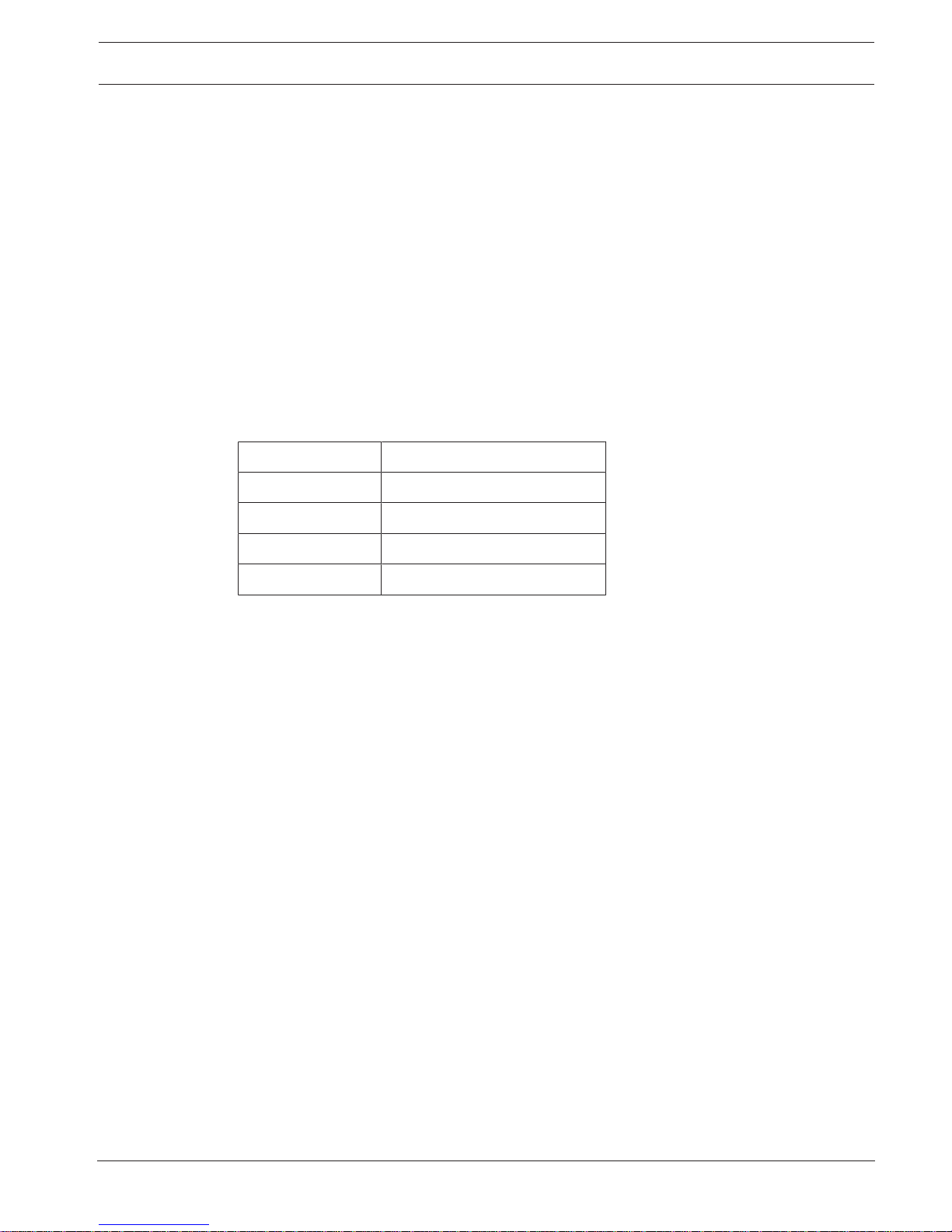
The table below shows the continuous SPLs (Sound Pressure Levels) achievable on-axis at
various distances from the loudspeaker for each of the three configurations, mounted at 3m
above floor level.
Distance VARI-B VARI-B+E VARI-B+E+E VARI-BH VARI-BH+E VARI-BH+E+E
20 m 90 dBA - - 89 dBA - -
32 m - 90 dBA - - 89 dBA -
50 m - - 88 dBA - - 87 dBA
VARI-BH base units employ co-axial drivers instead of the single-coil drivers fitted to the
VARI‑B. These give the line arrays an extended high-frequency response and this model is
better suited to applications where the audio system is to reproduce music as well as speech.
VARI extension units may be used to extend either VARI‑B or VARI‑BH base units. By adding
one or two extension units to either base unit, a total of six line array configurations can be
constructed. Refer to NoTrans Variables.
For easy identification an abbreviated array name has been defined for each of the possible
array compositions:
Array name Array composition Elements used
VARI-B VARI-BH VARI-E
Vari-array-B1 VARI-B 1 - -
Vari-array-B2 VARI-B+E 1 - 1
Vari-array-B3 VARI-B+E+E 1 - 2
Vari-array-H1 VARI-BH - 1 -
Vari-array-H2 VARI-BH+E - 1 1
Vari-array-H3 VARI-BH+E+E - 1 2
The mechanical mounting and coupling arrangements of the VARI units are designed to give
composite line arrays the smooth, finished appearance of a single unit when extension units
are employed.

8 en | System Overview VARI-directional array
2018.06 | V1.3 | Installation manual Bosch Security Systems B.V.
Figure3.1: VARI overview (grilles removed for identification)
VARI-directional array System Overview | en 9
Bosch Security Systems B.V. Installation manual 2018.06 | V1.3 |
VARI Configuration Set
A VARI‑CS Configuration Set consists of a computer interface and interconnection cables. It
should be ordered separately from the line arrays. A VARI‑CS Configuration Set can be used
repeatedly, on multiple installations. Bosch can accept no responsibility for the correct
functioning of any other type of computer interface; the use of OEM interfaces is not
recommended.
VARI CobraNet® Module
VARI base units may be fitted with an optional CobraNet® input module. CobraNet® is a
proprietary audio network protocol used widely in large infrastructures to carry multiple
channels of digital audio and other control data bi-directionally over Ethernet, using CAT-5
cable. The VARI‑CM module allows VARI line arrays to be directly interfaced to a CobraNet®
network.
Notice!
Note that this manual does NOT cover the configuration and operation of the CobraNet®
module. A description of CobraNet® can be found on www.cobranet.info. Here also
CobraNet® Discovery can be downloaded. This is the tool to discover and configure
CobraNet® interfaces, including the VARI CobraNet® module.

10 en | System Overview VARI-directional array
2018.06 | V1.3 | Installation manual Bosch Security Systems B.V.
3.1 What’s in the packaging
In addition to the line array itself, each VARI-B and VARI-BH base unit is shipped with the
following items:
Qty Item Use
1 Imporant Safety Instructions
1 Right-angled IEC connector (C13, rewireable) AC mains input
2 Cable tie, nylon Mains cable strain relief
4 Phoenix connectors, 3-pole, 3.81 mm-pitch Inputs (line level), failure relay,
control voltage
2 Phoenix connectors, 5-pole, 3.81 mm-pitch RS-485 in/out
2 Phoenix connectors, 2-pole, 5.08 mm-pitch Inputs (100 V line)
1 Phoenix connector, 2-pole, 7.62 mm-pitch DC power input
2 Hinged mounting bracket Wall mounting
4 30 mm hex-headed screws with washers and
wall plugs
Fixings for wall mounting
1 Grille removal tool Removal of front protective grille
In addition to the line array itself, each VARI-E extension unit is shipped with the following
items:
Qty Item Use
2 M5 x 12 mm hex-headed bolts Secure Extension to base unit
1 Hinged mounting bracket Wall mounting
2 30 mm hex-headed screws with washers and
wall plugs
Fixings for wall mounting
The VARI-CS Configuration Set comprises the following items:
Qty Item Use
1 USB to RS-485 interface, with manual Hardware interface
1 USB cable, 1.8 m
(USB Type A to USB Type B)
PC-to-interface cable
1 RS-485 cable, 5 m
(5-pin Phoenix to 5-pin Phoenix)
Interface-to-VARI cable

VARI-directional array Installation | en 11
Bosch Security Systems B.V. Installation manual 2018.06 | V1.3 |
4 Installation
This chapter of the manual takes you through the steps necessary to install a VARI line array
loudspeaker in the order in which they should be carried out. In summary, the steps are:
Preparation Making sure that you know where the unit is to be mounted.
Cabling Understanding which connections need to be made.
Assembly Adding any VARI-E extension units to the VARI base unit.
Connections Terminating all necessary cables correctly and connecting up.
Configuration Using the VariControl software to create the unit’s configuration file and
uploading it to the line array.
Mounting Mechanical installation of the unit.
4.1 Preparing for installation
Before starting to install the VARI loudspeaker, a number of points should be considered.
Mounting location:
VARI loudspeakers are designed to be mounted on a vertical surface – e.g., a wall or column. If
the vertical axis is tilted such that the loudspeaker is pointing “up” or “down” even a few
degrees, the effective sound coverage will be considerably impaired. Thus when choosing a
location, it is important that the positions which each of the mounting brackets will occupy
are in the same vertical plane. Similarly, the vertical axis should be perpendicular to the floor,
so that the loudspeaker is “upright”.
Figure4.1: Upright loudspeaker mounting
The mounting location should be chosen so that there is an unobstructed line-of-sight path
between the loudspeaker and the intended area of coverage - i.e., avoid mounting near
columns, external room corners or ceiling infrastructure items such as air conditioning,
lighting units, and the like.

12 en | Installation VARI-directional array
2018.06 | V1.3 | Installation manual Bosch Security Systems B.V.
Power supply
The VARI base unit requires an AC mains supply. Its internal power supply is of the autoswitching type, and will operate on voltages between 100 - 120 V or 200 - 240 V, at 50 or 60
Hz. It is equipped with power factor correction and has short circuit and over-temperature
protection. The installer should ensure that an AC mains supply of sufficient capacity is
available at the mounting location; note the peak mains power consumption in the table
below:
Configuration Max. power Idle power
VARI-B/BH 60 W 18 W
VARI-B/BH + VARI-E 97 W 23 W
VARI-B/BH + 2 x VARI-E 124 W 28 W
!
Warning!
The third terminal of the mains outlet must be connected to a proper safety ground.
Unpower the units during lighting storms or when unused for long periods of time, unless
special functions are to be maintained, such as for evacuation systems.
The VARI base unit (and thus any attached extension units) can also operate from a 24 V DC
power supply, and will automatically switch to this in the event of mains failure. This may be
sufficient to satisfy local safety regulations covering the use of sound systems in emergency
situations, but the installer should ensure that he/she is aware of the precise local
requirements in this respect. It may be necessary to provide a separate mains distribution
network or an uninterruptible mains power supply (UPS).
4.2 Power, Signal and Control cables
Since VARI loudspeakers will frequently be installed in locations which are difficult to access
readily, consideration should be given to the cables required at each mounting position. VARI
units will operate satisfactorily with just a signal input and the mains supply. However, some
installations will require further cables to be installed. It is recommended that all necessary
cables are run to the mounting location before the loudspeaker is physically installed. Note
that all external connections are made to the VARI base unit, at the bottom of the loudspeaker
column. Cable access is via a 37 mm diameter hole at the rear of the connector compartment.
Depending on local wiring regulations, it may be necessary for all cables to the VARI to be
contained in flexible conduit made of a material with a specific fire rating. A suitable bush to
terminate the conduit at the VARI will need to be fitted in the hole before the loudspeaker is
mounted in position.
Notice!
It will generally be necessary to mount the loudspeaker in position and feed the cables
through the rear cable access hole before the cables are terminated.
Connection Required? Cable type Section
AC Mains supply Always required 3-core mains cable AC mains supply,
page 13

VARI-directional array Installation | en 13
Bosch Security Systems B.V. Installation manual 2018.06 | V1.3 |
Connection Required? Cable type Section
Audio input 1 (line
level)
One of these inputs is
always required unless
system uses CobraNet®.
Others are optional.
1-pair audio cable Audio inputs,
page 13
Audio input 1 (100 V) 2-core speaker cable
Audio input 2 (line
level)
1-pair audio cable
Audio input 2 (100 V) 2-core speaker cable
Backup DC power Optional 2-core mains cable Backup DC power
supply, page 14
Failure relay Optional 2-core low current
cable
Failure relay,
page 14
Control input Optional 2-core low current
cable
Control input,
page 14
RS-485 network in Optional Network cable with 2
twisted pairs and
individual screens
RS-485 network,
page 14
RS-485 network thru Optional
CobraNet® input Optional - required when
system uses CobraNet®
CAT-5 network cable CobraNet® input,
page 15
4.2.1 AC mains supply
For ease of installation, the VARI base unit is delivered with a rewireable angled IEC mains
power cable connector. Only this connector may be used and should be fitted to a power cord
of the required length. Refer to section Connector and wiring details, page 23.
4.2.2 Audio inputs
The VARI base unit provides two input channels that accept audio signals at either line level (0
dBV), or from a 100 V line speaker distribution system. Use the line level inputs if the signal
source is a standard item of audio equipment such as a mixer. Use the 100 V inputs if the VARI
is being installed as part of a system which uses other 100 V line loudspeakers. The line level
inputs are transformer-balanced, and the 100 V inputs transformer-coupled. For the input type
being used, Input 1 should be connected to the “normal” signal source. Input 2, if used, may
be connected to a secondary audio feed, such as the output of a paging system, spot
announcement player or emergency announcement system.
Refer to section Line level input 1 (4) and 2 (5), page 25 and 100 V input 1 (6) and 2 (7), page
25 for wiring details.

14 en | Installation VARI-directional array
2018.06 | V1.3 | Installation manual Bosch Security Systems B.V.
4.2.3 Backup DC power supply
The VARI base unit is equipped with a backup DC power input. In the event of AC mains
failure, the internal power supply will automatically switch to this backup input, allowing the
loudspeaker to continue operation under what may be emergency conditions.
The backup DC supply will typically be from batteries, and should be 24 V.
Note that the current drawn by the VARI unit from the backup supply will be much higher than
that drawn from the AC-mains, and the cable used must have an adequate current rating.
Refer to section Backup DC power supply input (2), page 24 for wiring details.
4.2.4 Failure relay
If network monitoring is not to be used (see below), a simple surveillance function may be
realised by use of the VARI’s failure relay. The failure relay connector provides both volt-free
and switched-impedance contacts, the latter suitable for impedance-sensing fault-monitoring
equipment.
Refer to section Failure relay (11), page 28 for wiring details.
4.2.5 Control input
The VARI is fitted with an external control port which can be used to load an internal
“emergency” configuration in the form of a preset from memory in the event of, e.g., network
failure.
Refer to section External control input (10), page 28 for wiring details.
4.2.6 RS-485 network
The VARI’s RS‑485 connection is primarily the method by which it gets configured using the
VariControl software application. The unit’s configuration file will generally be loaded before
mechanical installation, using the cable supplied with the VARI‑CS Configuration Set.
Additionally, continuous monitoring of the unit’s performance and external control may be
realised via the RS‑485 connection. If this feature is to be implemented, a permanent RS‑485
network connection will need to be run to the VARI’s installed location. In that case the
configuration file can just as easy be loaded after mechnical installation.
The VARI has two identical RS‑485 connectors, paralleled internally, allowing multiple VARI
units to be easily “daisy‑chained”.
The type of cable necessary for correct operation of the RS‑485 network is twin twisted pair
with each pair individually shielded. Numerous cables of this type are readily available and
cables broadly meeting the specifications of the example cable given below are likely to be
suitable. Example of a preferred cable type:
Parameter Value
Type BELDEN ‘Datalene’ series No. 9729 2-pair, pairs
individually screened
Characteristic impedance 100 ohms
Capacitance (core to core) 41 pF/m
Capacitance (core to screen) 72.5 pF/m
DC resistance (core) 78.7 ohms/km
DC resistance (screen) 59.1 ohms/km
Refer to section RS-485 network in (8) and thru (9), page 26 for wiring details.
 Loading...