


LBB1990/00
Table of contents
 Loading...
Bosch LBB1990/00, LBB1992/00, LBB1994/00, LBB1995/00, LBB1996/00 System Manual
...
Plena Voice Alarm System
Basic System Manual
Voice Alarm Systemen


Plena Voice Alarm System | Basic System Manual | Important Safeguards en | 3
Important Safeguards
Prior to installing or operating this product, always read
the Important Safety Instructions which are available as
a separate document (9922 141 7014x). These
instructions are supplied together with all equipment
that can be connected to the mains.
Bosch Security Systems | 2005-04 | 9922 141 10364en

Plena Voice Alarm System | Basic System Manual | Important Notices en | 4
Important Notices
When using routers, keypads or more than one call
station, configure the controller using the supplied
software.
Use shielded cable (Cat-5) between the routers and the
controller. Do not connect the shield to both the
controller and the router!
The factory default setting of the Plena Voice Alarm
Controller is as follows:
• Stand-alone unit configured for an ISO 60849
compliant system when used with a spare power
amplifier from the Plena range and compliant wiring
and loudspeakers.
• One channel system.
• Supervision on for:
• Loudspeaker lines
(90 seconds interval, 15% accuracy)
• Main and spare power amplifier
• Short to ground (“Ground short”)
• Mains and battery power
•EMG mic
•Memory
Please note that when used with the factory default
configuration:
• The background music (BGM) is muted when no
spare power amplifier is connected. Disabling the
spare power amplifier supervision or overall
supervision restores the BGM.
• The BGM will not be present in non-selected zones
during a call. If this is desired, connect a spare/call
power amplifier and switch the system to 2-channel
mode.
Thank you for choosing a Bosch Security Systems
product.
Bosch Security Systems | 2005-04 | 9922 141 10364en

Plena Voice Alarm System | Basic System Manual | Table of Contents en | 5
Table of Contents
Important Safeguards ..................................................................................................................................................3
Important Notices ..........................................................................................................................................................4
Table of Contents ..........................................................................................................................................................5
1. Introduction ....................................................................................................................................................................9
1.1 Purpose .....................................................................................................................................................................................9
1.2 Digital document .....................................................................................................................................................................9
1.3 Intended audience ..................................................................................................................................................................9
1.4 Related documentation ..........................................................................................................................................................9
1.5 Alerts ..........................................................................................................................................................................................9
1.6 Signs ..........................................................................................................................................................................................9
1.7 Conversion tables ................................................................................................................................................................10
2. System Overview ....................................................................................................................................................... 11
2.1 Voice Alarm System ............................................................................................................................................................11
2.1.1 Introduction ......................................................................................................................................................................11
2.1.2 Application types ............................................................................................................................................................11
2.1.3 Application areas ............................................................................................................................................................ 11
2.1.4 Plena ..................................................................................................................................................................................11
2.2 Basic system ......................................................................................................................................................................... 11
2.3 Voice alarm controller .......................................................................................................................................................... 12
2.3.1 Introduction ......................................................................................................................................................................12
2.3.2 Hand-held microphone ..................................................................................................................................................12
2.3.3 Internal power amplifier .................................................................................................................................................12
2.3.4 Internal message manager ...........................................................................................................................................12
2.3.5 Supervision ......................................................................................................................................................................12
2.3.6 Overview ...........................................................................................................................................................................12
2.4 Call station .............................................................................................................................................................................15
2.4.1 Introduction ......................................................................................................................................................................15
2.4.2 Overview ...........................................................................................................................................................................16
3. Installation ................................................................................................................................................................... 17
3.1 Introduction ............................................................................................................................................................................17
3.2 Requirements ........................................................................................................................................................................17
3.3 Unpacking ..............................................................................................................................................................................17
3.4 CD-ROM ................................................................................................................................................................................17
3.5 Hardware installation ...........................................................................................................................................................17
3.6 Emergency microphone ...................................................................................................................................................... 18
3.7 BGM inputs ...........................................................................................................................................................................18
3.8 Call station .............................................................................................................................................................................19
3.9 External power amplifier ...................................................................................................................................................... 19
3.10 Loudspeakers ........................................................................................................................................................................20
3.11 Volume overrides .................................................................................................................................................................. 21
3.12 Line output .............................................................................................................................................................................23
3.13 Mic/line input with VOX functionality ...............................................................................................................................24
3.14 Status output contacts .......................................................................................................................................................25
3.15 Power ......................................................................................................................................................................................25
3.15.1 Introduction ......................................................................................................................................................................25
3.15.2 Mains power .................................................................................................................................................................... 25
Bosch Security Systems | 2005-04 | 9922 141 10364en

Plena Voice Alarm System | Basic System Manual | Table of Contents en | 6
3.15.3 Back-up power ................................................................................................................................................................26
4. Configuration .............................................................................................................................................................. 27
4.1 Introduction ............................................................................................................................................................................27
4.2 System settings .................................................................................................................................................................... 27
4.2.1 Introduction ......................................................................................................................................................................27
4.3 Monitor .................................................................................................................................................................................... 27
4.4 APR mode ..............................................................................................................................................................................27
4.5 Supervision ............................................................................................................................................................................28
4.5.1 Introduction ......................................................................................................................................................................28
4.5.2 Overview ...........................................................................................................................................................................28
4.5.3 Processor supervision ................................................................................................................................................... 28
4.5.4 Message supervision ..................................................................................................................................................... 29
4.5.5 Line supervision .............................................................................................................................................................. 29
4.5.6 Emergency microphone ................................................................................................................................................29
4.5.7 Mains power supervision .............................................................................................................................................. 29
4.5.8 Battery supervision ......................................................................................................................................................... 29
4.5.9 Internal power amplifier supervision ...........................................................................................................................29
4.5.10 External power amplifier supervision ..........................................................................................................................29
4.5.11 1 channel and 2 channel operation ............................................................................................................................30
4.6 VOX configuration ................................................................................................................................................................ 30
4.6.1 Introduction ......................................................................................................................................................................30
4.6.2 Vox ..................................................................................................................................................................................... 31
4.6.3 Speech filter ..................................................................................................................................................................... 31
4.6.4 Phantom power ...............................................................................................................................................................31
4.7 Call station .............................................................................................................................................................................31
4.7.1 Introduction ......................................................................................................................................................................31
4.7.2 Call station ID .................................................................................................................................................................. 31
4.7.3 Sensitivity .........................................................................................................................................................................32
4.7.4 Speech filter ..................................................................................................................................................................... 32
4.7.5 Termination .......................................................................................................................................................................32
5. Operation ..................................................................................................................................................................... 33
5.1 Switch on ............................................................................................................................................................................... 33
5.2 Switch off ............................................................................................................................................................................... 33
5.3 Calibration ..............................................................................................................................................................................33
5.4 Background music ............................................................................................................................................................... 33
5.4.1 Introduction ......................................................................................................................................................................33
5.4.2 Select BGM source ....................................................................................................................................................... 33
5.4.3 Select zones ....................................................................................................................................................................34
5.4.4 Adjust volume .................................................................................................................................................................. 34
5.4.5 Adjust frequencies .........................................................................................................................................................34
5.5 Business calls .......................................................................................................................................................................35
5.5.1 Introduction ......................................................................................................................................................................35
5.5.2 Select zones ....................................................................................................................................................................35
5.5.3 Make the announcement .............................................................................................................................................. 35
5.6 Emergency state ................................................................................................................................................................... 36
5.6.1 Introduction ......................................................................................................................................................................36
5.6.2 Enter the emergency state ...........................................................................................................................................36
5.6.3 Acknowledge the emergency state ............................................................................................................................ 36
Bosch Security Systems | 2005-04 | 9922 141 10364en

Plena Voice Alarm System | Basic System Manual | Table of Contents en | 7
5.6.4 Exit the emergency state ............................................................................................................................................... 36
5.6.5 Distribute live speech .................................................................................................................................................... 36
5.6.6 Distribute the alert message ........................................................................................................................................ 38
5.6.7 Distribute the alarm message ...................................................................................................................................... 39
5.7 Fault state .............................................................................................................................................................................. 39
5.7.1 Introduction ......................................................................................................................................................................39
5.7.2 Acknowledge the fault state ........................................................................................................................................ 39
5.7.3 Reset the fault state ....................................................................................................................................................... 39
5.7.4 Fault indicators ................................................................................................................................................................40
6. Technical data ............................................................................................................................................................. 43
6.1 LBB1956/00 ......................................................................................................................................................................... 43
6.1.1 Electrical ...........................................................................................................................................................................43
6.1.2 Performance .................................................................................................................................................................... 43
6.1.3 Interconnection ............................................................................................................................................................... 43
6.1.4 Environmental conditions .............................................................................................................................................. 43
6.1.5 General .............................................................................................................................................................................43
6.2 LBB1990/00 ......................................................................................................................................................................... 43
6.2.1 Electrical ...........................................................................................................................................................................43
6.2.2 Message manager .......................................................................................................................................................... 44
6.2.3 Internal power amplifier .................................................................................................................................................44
6.2.4 Interconnection ............................................................................................................................................................... 44
6.2.5 Loudspeaker outputs .....................................................................................................................................................44
6.2.6 Overrides ..........................................................................................................................................................................44
6.2.7 Trigger outputs ................................................................................................................................................................44
6.2.8 Trigger inputs/24 V DC out ......................................................................................................................................... 45
6.2.9 Mic/line input with VOX functionality .........................................................................................................................45
6.2.10 BGM ..................................................................................................................................................................................45
6.2.11 Line out .............................................................................................................................................................................45
6.2.12 External power amplifier ................................................................................................................................................ 45
6.2.13 Environmental conditions .............................................................................................................................................. 45
6.2.14 General .............................................................................................................................................................................45
7. Glossary ........................................................................................................................................................................ 47
8. Product Index .............................................................................................................................................................. 49
Bosch Security Systems | 2005-04 | 9922 141 10364en

Plena Voice Alarm System | Basic System Manual | Table of Contents en | 8
Intentionally left blank.
Bosch Security Systems | 2005-04 | 9922 141 10364en
Plena Voice Alarm System | Basic System Manual | Introduction en | 9
1 Introduction
1.1 Purpose
The purpose of the Basic System Manual is to provide
information that is required to install, configure and
operate a basic Plena Voice Alarm System. By
definition, such a system is installed, configured and
operated without a PC.
1.2 Digital document
The Basic System Manual is also available as a digital
document in the Adobe Portable Document Format
(PDF). All references to pages, figures, tables, etc. in this
digital document contain hyperlinks to the referenced
location.
1.3 Intended audience
The Basic System Manual is intended for installers and
users of a basic Plena Voice Alarm System. Installers
and users of extensive systems should refer to the
Installation and User Instructions (see section 1.4).
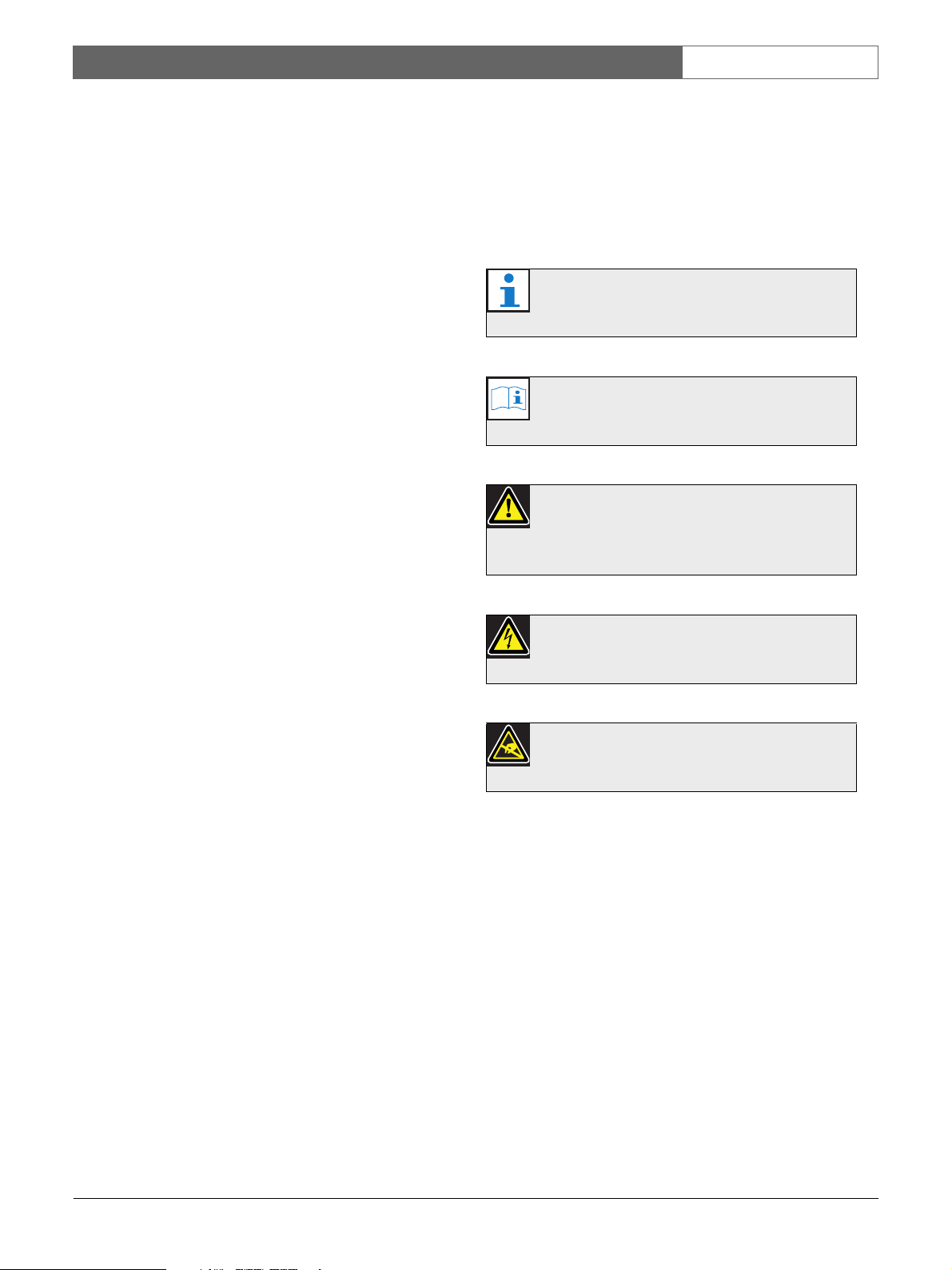
1.6 S ign s
Except for note alerts, the nature of the effect that can
be caused when the alert is not observed, is indicated
using a sign. For note alerts, the sign provides more
information about the note itself. In this manual, the
following signs are used in combination with alerts:
Note
General sign for notes.
Note
Consult the indicated source of information.
Caution, Warning, Danger
General sign for cautions, warnings and
dangers.
1.4 Related documentation
The following related documents are available:
• Plena Voice Alarm System Installation and User
Instructions (9922 141 1037x).
• Plena Voice Alarm System Configuration Software
Manual (9922 141 1038x).
1.5 Alerts
In this manual, four types of alerts are used. The alert
type is closely related to the effect that may be caused
when it is not observed. These alerts - from least severe
effect to most severe effect - are:
• Note
Alert containing additional information. Usually, not
observing a note alert does not result in damage to
the equipment or personal injuries.
• Caution
The equipment can be damaged if the alert is not
being observed.
• War ning
Persons can be (severely) injured or the equipment
can be seriously damaged if the alert is not being
observed.
• Danger
Not observing the alert can result in death.
Caution, Warning, Danger
Risk of electric shock.
Caution, Warning, Danger
Risk of electrostatic discharges.
Bosch Security Systems | 2005-04 | 9922 141 10364en
Plena Voice Alarm System | Basic System Manual | Introduction en | 10
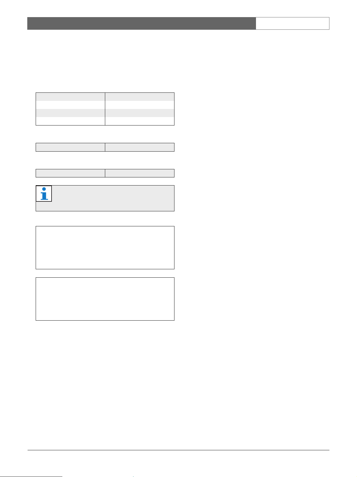
1.7 Conversion tables
In this manual, SI units are used to express lengths,
masses, temperatures etc.. These can be converted to
non-metric units using the information provided below.
table 1.1: Conversion of units of length
1 in = 25.4 mm 1 mm = 0.03937 in
1 in = 2.54 cm 1 cm = 0.3937 in
1 ft = 0.3048 m 1 m = 3.281 ft
1 mi = 1.609 km 1 km = 0.622 mi
table 1.2: Conversion of units of mass
1 lb = 0.4536 kg 1 kg = 2,2046 lb
table 1.3: Conversion of units of pressure
1 psi = 68.95 hPa 1 hPa = 0.0145 psi
Note
1 hPa = 1 mbar.
°F
° C
9
---
°C 32+⋅=
5
5
---
°F 32–()⋅=
9
Bosch Security Systems | 2005-04 | 9922 141 10364en
Plena Voice Alarm System | Basic System Manual | System Overview en | 11
2 System Overview
2.1 Voice Alarm System
2.1.1 Introduction
The Plena Voice Alarm System is a public address and
voice alarm system in which all the necessary features
for compliance to evacuation standards such as
IEC60849, NEN2575 and BS5839/8 are integrated.
2.1.2 Application types
Typically, the Plena Voice Alarm System is used to
create small systems that must comply to evacuation
standards, medium-sized systems in which one call
channel is enough and large systems that consist of
many small zones.
2.1.3 Application areas
The application areas of the Plena Voice Alarm System
include:
• Supermarkets, shops
•Factories
• High-rise buildings
• Office buildings
•Schools
• Recreational facilities
•Hotels
• Small airports
2.1.4 Plena
The Plena Voice Alarm System is part of the Plena
product range. Plena provides public address solutions
for places where people gather to work, worship, trade
or simply enjoy themselves. It is a family of system
elements that are combined to create public address
systems tailored for virtually any application. The range
includes mixer, pre, system and power amplifiers, a
source unit, digital message manager, feedback
suppressor, conventional and PC call stations, an ‘All-inOne’ system and a voice alarm system. Each element is
designed to complement all others thanks to matched
acoustical, electrical and mechanical specifications.
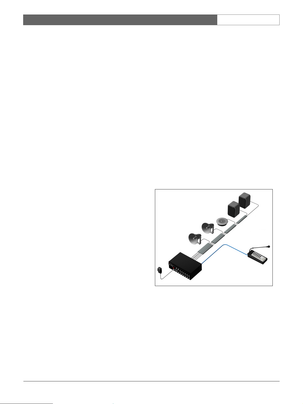
2.2 Basic system
As mentioned before, the scope of this manual is a basic
system. By definition, a basic system is installed,
configured and operated without a PC. Such a system
can only consist of:
• 1x LBB1990/00 Voice Alarm Controller (required).
• 1x LBB1956/00 Call Station (optional).
LBB1956/00
Bosch Security Systems | 2005-04 | 9922 141 10364en
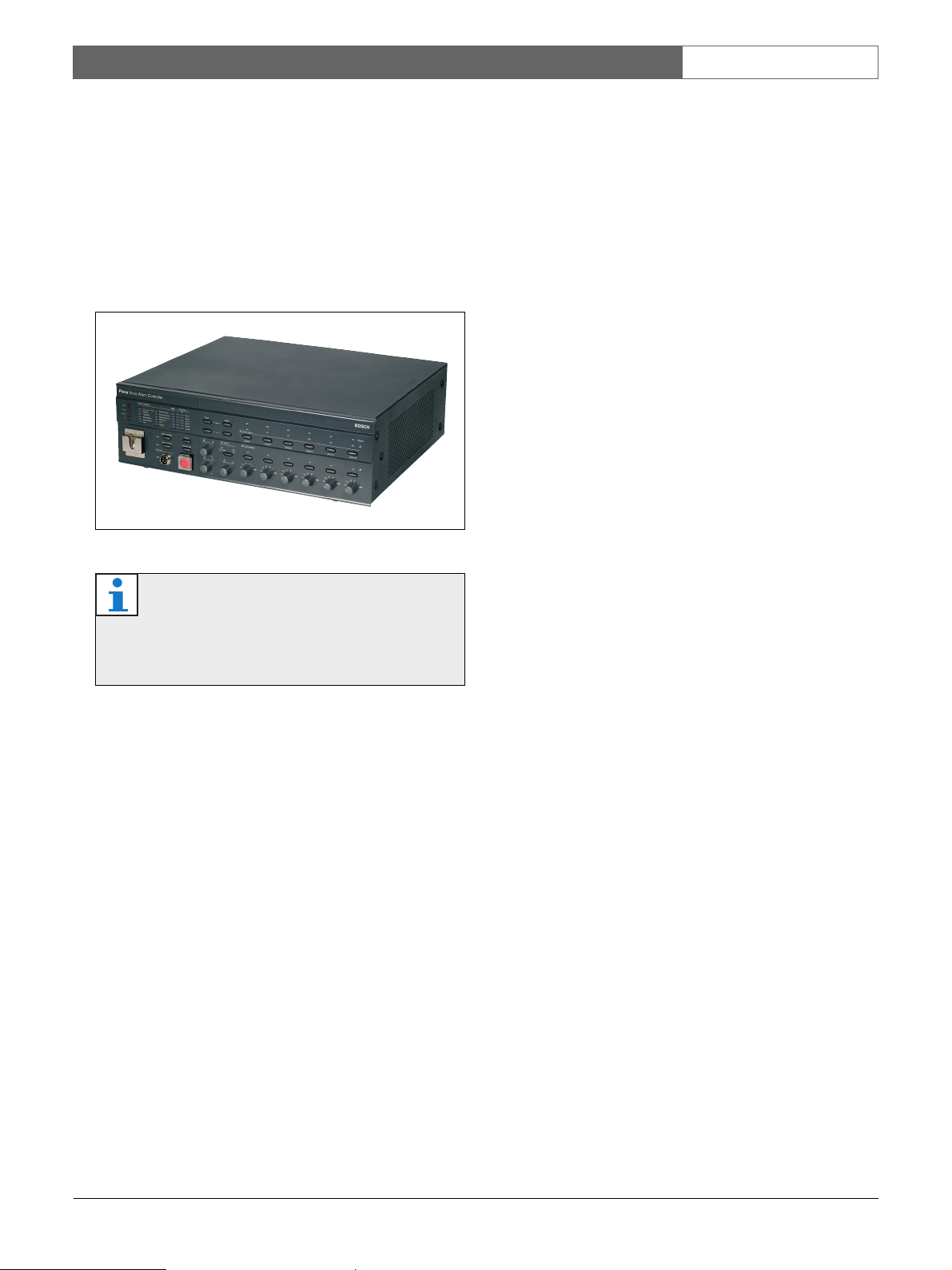
LBB1990/00
figure 2.1: Basic system
Plena Voice Alarm System | Basic System Manual | System Overview en | 12
2.3 Voice alarm controller
2.3.1 Introduction
The LBB1990/00 Voice Alarm Controller is the heart of
the Plena Voice Alarm System. The voice alarm
controller distributes emergency calls, business calls as
well as background music (BGM) to up to 6 loudspeaker
zones.
figure 2.2: Voice Alarm Controller
Note
When the voice alarm controller has been
purchased in the Asian-Pacific Region, the
emergency button has a different cover.
2.3.2 Hand-held microphone
The voice alarm controller is equipped with a hand-held
microphone, which can be used to make emergency
calls.
2.3.3 Internal power amplifier
The voice alarm controller has a 240 W internal power
amplifier, which can be used in 1-channel or 2-channel
mode. In the 1-channel mode, all calls and BGM are
amplified by the internal power amplifier. If desired, an
external power amplifier can be connected for spare
switching. In the 2-channel mode, the BGM is amplified
by the internal power amplifier, whereas the calls are
amplified by an external power amplifier.
2.3.4 Internal message manager
The voice alarm controller has an internal message
manager, which maps wave files (.wav) to messages that
can be played by the Plena Voice Alarm System.
2.3.5 Supervision
All necessary supervision features for compliance to
evacuation standards are integrated into the voice alarm
controller. If supervision is enabled and a fault is
detected, the voice alarm controller lights a LED on its
front panel that indicates the cause of the fault.
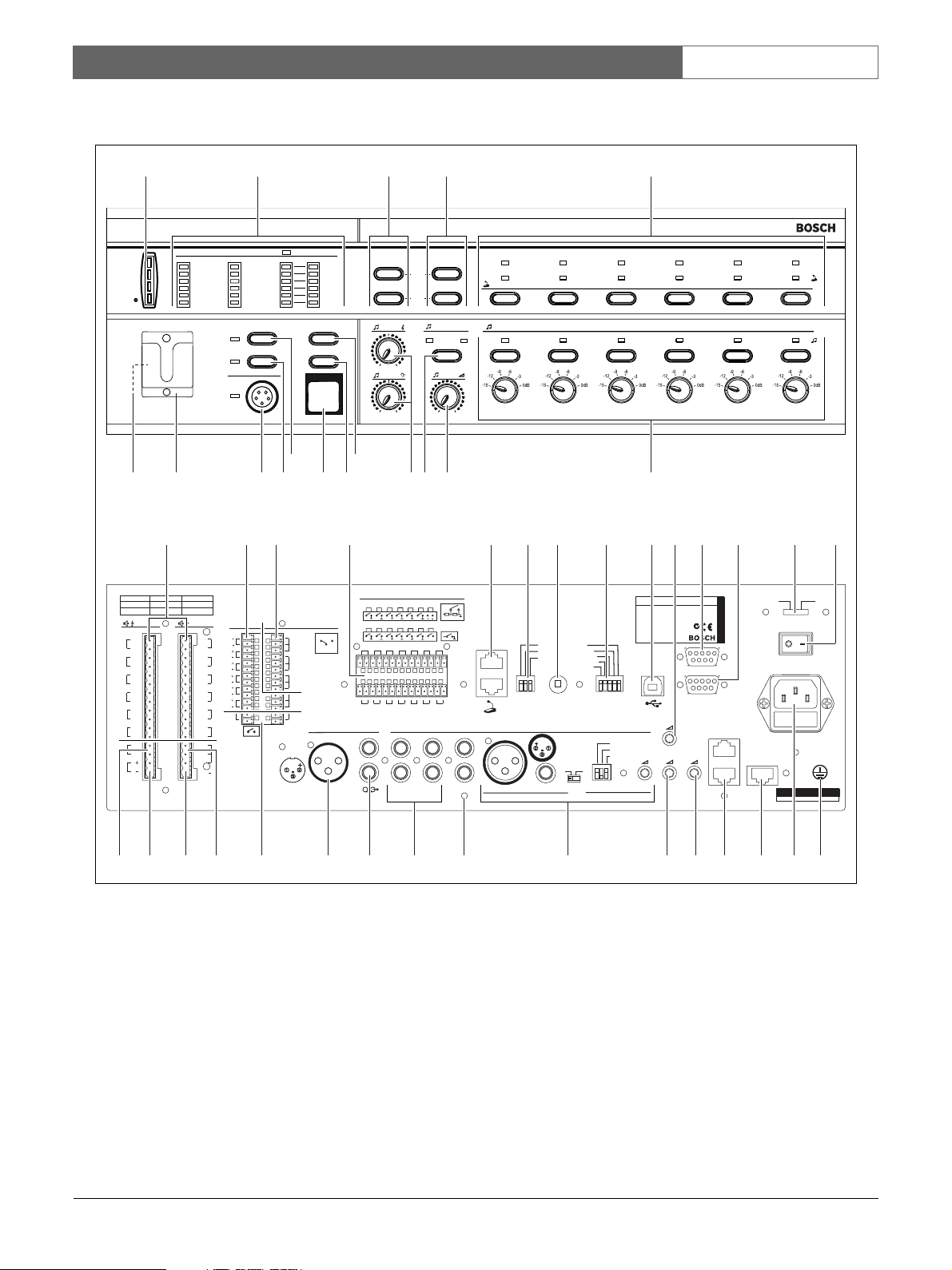
2.3.6 Overview
See figure 2.3 for an overview of the controls,
connections and indicators on the voice alarm
controller:
1 Power LED/VU Meter - A combined power
indicator and VU meter. The green power LED is lit
if the voice alarm controller is connected to the
mains or back-up power and switched on. The VU
meter indicates the master VU level: 0 dB (red), - 6
dB, -20 dB (yellow).
2 Fault indicators - Twelve yellow system fault
LEDs (Processor reset, Network, Call/EMG, Music/
Spare, Ground short, Input, Mains, Battery, Message,
EMG mic, RCP and Router) and twelve yellow
loudspeaker line fault LEDs. Fault indication is only
possible if supervision is enabled (see section 5.7). If
supervision is disabled, the yellow Disabled LED is
lit.
3 Fault state buttons - Two buttons to acknowledge
(Ack) and reset (Reset) the fault state (see section
5.7).
4 Emergency state buttons - Two buttons to
acknowledge (Ack) and reset (Reset) the emergency
state (see section 5.6).
5 Emergency call zone selectors - Six buttons to
select the zones to which the emergency call must be
distributed (see section 5.6). Each button has a green
and a red LED. The six red LEDs indicate the zones
that are selected for the emergency call. The six
green LEDs indicate the zones in which a business
call is running.
Bosch Security Systems | 2005-04 | 9922 141 10364en
Plena Voice Alarm System | Basic System Manual | System Overview en | 13
1
Plena Voice Alarm C
Fault Indicators
-20dB
0dB
-6dB
Processor reset
Network
Call/EMG
Music/Spare
Ground short
Input
18 19 20 22 23 24 25 26 27 28 30 312921
2Channel
1Channel
IntBooster
ExtBooster
AB
100 V
Z1
0
100 V
Z2
0
100 V
Z3
0
100 V
Z4
0
100 V
Z5
0
100 V
Z6
0
Ext
100 V
Booster
In
0
DC In
24V
BGM/ C all
N.C./Spare
BGM/Spare
Call
100 V
0
100 V
0
100 V
0
100 V
0
100 V
0
100 V
0
100 V
70V
0
100 V
2 3 4 5
ontroller
Disabled
A
EMGmic
Mains
Battery
Message
EMGmic
RCP
Router
Alert message
Alarm message
B
Zone1
Zone2
Zone3
Zone4
Zone5
Zone6
All call
Indicator test
Fault
-
-
EMG
Ack
Reset
Select
CD/Tuner
Zone select
Zone1 Zone2 Zone3 Zone4 Zone5 Zone6
Zone select
Aux
+
0
+
1013
In
CD/Tuner
89
24V
DCout
10k
10k
VOX
Switch
AUX
DC out
VOXSwitch
Call station
24V
PC
For service only
SEL1
SEL0
Firmware
Upgrade
1
Off
2
On
Impedance
Calibration
L
R
GND
Mic/Line
Override/TriggerOutput
24V
Z1
Z1
Z2
Z2
Z3
Z4
Z3
Z5
Z4
Z6
Z5
TRG 1
Z6
Int
Booster
Out
Call out
1114
Triggerinput/24V DC out
Emergency
123456
Business
NC
NC
COM
EMG
NO
NC
COM
Fault
NO
NC
COM
Call
NO
NC
24V
VolumeOverride
NO
TRG2
Out
GND
External Booster
123456
NO
123456
COM
123456
Monitor
APR mode
Supervision
2ch operation
Reserved
Vox
6712151617
LBB1990/00 8900199 0 0001
Plena Voice Alarm Controller
Max.output power 360W
Rated output power 240W
115-230V~,50/6 0Hz
S/N.
USB
Off
On
Vox
Speech filter
Phantompower
Off
On
Design& Quality
TheNetherlands
EMG.Mic
Digital
Mess age
N663
Linefuse
T6.3L250Vfor230V AC
T10L250V for115VAC
RemoteControl Panel
Monitoring
Speaker
Alarm
230V~
115V~
Apparatusdelivered
RS232
Reserved
1
Router
2
Connected for 230V~
Ratedinput power :760 VA
Warning
Thisapparatus must be earthed
Power
Made in China
4445 43
figure 2.3: Front and rear views of the voice alarm controller
6 BGM zone selectors - Six buttons to select the
zones to which the BGM is distributed (see section
5.4). Each button has a green LED and a rotary
knob. The six green LEDs indicate the zones to
which BGM is distributed. The six rotary knobs are
local volume controls that can be used to adjust the
volume of the BGM in each zone.
Bosch Security Systems | 2005-04 | 9922 141 10364en
384041424647
32333435363739
7 BGM master volume control - A rotary knob to
set the master volume of the BGM (see section 5.4).
8 BGM source selector - A button to select the
BGM source (CD/Tuner or Aux). The selected source
is indicated with a green LED (see section 5.4).
9 BGM tone controls - Two rotary knobs to control
the high and low frequencies of the BGM (see
section 5.4).

Plena Voice Alarm System | Basic System Manual | System Overview en | 14
10 All call button - A button to select all zones. This
button is only available in the emergency state (see
section 5.6).
11 Indicator test button - A button to test all LEDs
on the front panel of the voice alarm controller. All
LEDs are lit as long as the button is pushed (see
section 5.7).
12 Emergency button - A push button to put the
system in the emergency state (see section 5.6).
13 Alert message button - A button to select the
alert message. This button is only available in the
emergency state (see section 5.6).
14 Alarm message button - A button to select the
default alarm message. This button is only available
in the emergency state (see section 5.6).
15 Microphone socket - A socket to connect the
hand-held emergency microphone (see section 3.6).
16 Bracket - A bracket for the hand-held emergency
microphone that is supplied with the voice alarm
controller.
17 Monitoring speaker - Built-in monitoring
speaker.
18 Zone outputs - Six zone outputs to connect
loudspeakers to the voice alarm controller. Each
zone output consists of two loudspeaker line outputs
(see section 3.10).
19 Override outputs - Six volume override outputs to
override local volume controls in each zone (see
section 3.11).
20 Status outputs - Three status outputs to send the
status of the Plena Voice Alarm System to third party
equipment (see section 3.14).
21 Trigger inputs/24 V DC output - Twelve trigger
inputs to receive signals from third party equipment
and one 24 V(DC) output. Except for the VOX
switch input and the 24V DC out output, these must
be configured with the configuration software and
are therefore not used in basic systems (see section
3.13).
22 Call station sockets - Two redundant RJ45
sockets to connect call stations (LBB1956/00) to the
voice alarm controller (see section 3.8).
23 Service settings - A set of DIP switches to service
the voice alarm controller. Do not change the
positions of the switches.
24 Calibration switch - A switch to calibrate the
impedances of the loudspeaker lines for loudspeaker
supervision (see section 4.5.5.3).
25 Configuration settings - A set of DIP switches to
configure the voice alarm controller (see section 4.2).
26 PC socket - A USB socket to connect the voice
alarm controller to a PC. Not for use in basic
systems.
27 Emergency microphone volume control - A
rotary knob to set the volume of the hand-held
emergency microphone.
28 Reserved - For future use.
29 Reserved - For future use.
30 Voltage selector - A voltage selector to select the
local mains voltage (see section 3.15).
31 Power switch - A switch to switch the voice alarm
controller on and off (see section 5.1).
32 Ground - A connection to electrically ground the
voice alarm controller.
33 Mains power inlet - A socket to connect the voice
alarm controller to the mains power (see section
3.15).
34 Router socket - An RJ45 socket to connect voice
alarm routers (LBB1992/00) to the voice alarm
controller. Not for use in basic systems.
35 Remote control panel socket - Two redundant
RJ45 sockets to connect remote control panels
(LBB1995/00, LBB1996/00, LBB1997/00) to the
voice alarm controller. Not for use in basic systems.
36 Monitoring speaker volume control - A rotary
knob to set the volume of the monitoring
loudspeaker.
37 Digital message volume control - A rotary
knob to set the volume of the digital business
messages. This volume control does not influence
the volume of the emergency messages.
38 Mic/line input with VOX functionality - An
XLR socket and a 6.3 mm jack with voice-activated
(VOX) functionality to connect a microphone or line
input to the voice alarm controller (see section 3.13).
The VOX settings are configured with the DIP
switches and the source switch (see section 4.6).
39 PC Call station input - An input to connect a PC
call station. Not for use in basic systems.
Bosch Security Systems | 2005-04 | 9922 141 10364en
Plena Voice Alarm System | Basic System Manual | System Overview en | 15
40 BGM inputs - Two inputs to connect background
music sources. Each input consists of two cinch
sockets (see section 3.7).
41 Line output - A line output to connect an external
recording device to record the audio of the Plena
Voice Alarm System (see section 3.12).
42 External power amplifier (output) - An XLR
socket to connect an external power amplifier (see
section 3.9). This socket is used in combination with
the external power amplifier input (no. 47).
43 Trigger outputs - Two general purpose trigger
outputs. Not for use in basic systems.
44 Internal power amplifier output - Three pins
that provide the 100 V audio signal of the internal
power amplifier of the voice alarm controller.
45 Call output - An output that provides the call audio
of the Plena Voice Alarm System.
46 Back-up power inlet - An inlet to connect a back-
up power supply to the voice alarm controller (see
section 3.15).
47 External power amplifier (input) - An input to
connect an external power amplifier (see section 3.9).
These pins are used in combination with the external
power amplifier output (no. 42).
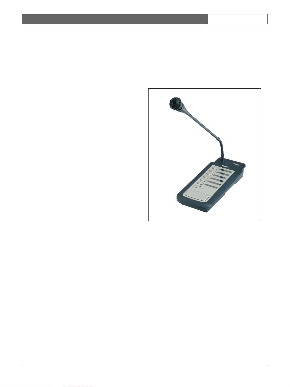
2.4 Call station
2.4.1 Introduction
The LBB1956/00 Call Station can be connected to the
LBB1990/00 Voice Alarm Controller to make business
calls. The call station is connected to the voice alarm
controller using standard Cat-5 Ethernet cable.
figure 2.4: Call Station
The call station is not supervised. For compliance to
evacuation standards, the Plena Voice Alarm System
disables the call station during emergency calls.
Bosch Security Systems | 2005-04 | 9922 141 10364en
Plena Voice Alarm System | Basic System Manual | System Overview en | 16
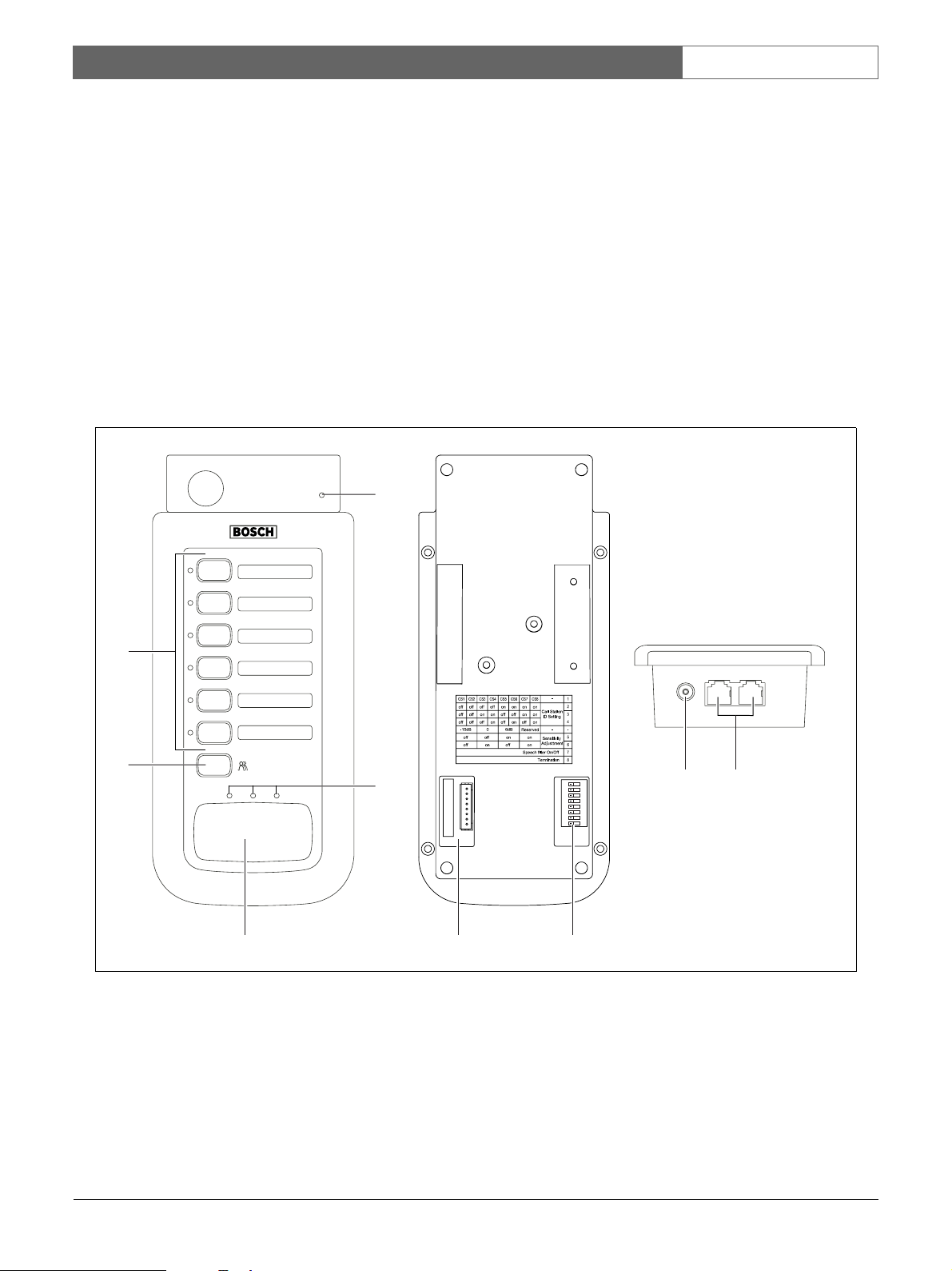
2.4.2 Overview
See figure 2.5 for an overview of the controls, indicators
and connectors on the call station:
1 Power indicator - A green LED to indicate that
the call station is powered on.
2 Zone selection buttons - Six buttons to select the
zones to which the business call is distributed (see
section 5.5). Each button has a green LED, which
indicates the zones to which the business call is
distributed.
3 ‘All call’ selector - A button to select all zones
(see section 5.5).
4 Push-to-talk button - A push-to-talk (PTT) button
to start the business call.
Plena
1
5 Status indicators - Three LEDs that indicate the
status of the call station (see section 5.5).
6 Keypad connector - A connector to connect call
station keypads (LBB1957/00) to the call station.
7 Configuration settings - A set of DIP switches to
configure the call station (see section 4.7).
8 Power supply inlet - A socket to connect a
24 V(DC) power supply (see section 3.8).
9 System sockets - Two redundant RJ45 sockets to
connect the call station to the voice alarm controller
(LBB1990/00, see section 3.8).
2
3
5
4
figure 2.5: Top and bottom views of the call station
12345678
6 7
ON
8
9
Bosch Security Systems | 2005-04 | 9922 141 10364en
Loading...