


Bosch HBL8752UC, HMC80152UC, HMC80252UC, HMC80242UC, HMC87152UC Installation Instructions
...Built-In Convection Microwave Oven (Speed Oven)
Installation Manual
800 SERIES
HMC87152UC HMC80152UC HMC80252UC HMCP0252UC HMC80242UC

Table of Contents |
|
Safety Definitions .......................................................... |
2 |
IMPORTANT SAFETY INSTRUCTIONS ........................ |
3 |
Appliance Handling Safety ................................................. |
3 |
Safety Codes and Standards ............................................. |
3 |
Electric Safety ....................................................................... |
3 |
Microwave Safety ................................................................. |
3 |
Related Equipment Safety .................................................. |
4 |
State of California Proposition 65 Warnings: .................. |
4 |
Before you begin ........................................................... |
5 |
Tools and parts needed ...................................................... |
5 |
Parts included ....................................................................... |
5 |
Power Requirements ........................................................... |
5 |
Checklist for Installation ............................................... |
5 |
Removing Packaging .................................................... |
5 |
Dimensions and Cabinet Requirements ...................... |
6 |
General Cabinet Requirements ......................................... |
6 |
Outlet Area ............................................................................ |
6 |
Dimensions for 30" Wall-Mounted Units .......................... |
6 |
Dimensions for 27” Wall-Mounted Units ......................... |
7 |
Electrical Installation - GROUNDING INSTRUCTIONS 8 |
|
Electrical Connection with Plug ......................................... |
8 |
Electrical Connection with Wire Conduit ......................... |
8 |
Install Appliance ............................................................ |
9 |
Mount to Cabinet .................................................................. |
9 |
Testing Operation ......................................................... |
9 |
Bosch® Support ........................................................... |
10 |
Before Calling Service ..................................................... |
10 |
Data Plate ........................................................................... |
10 |
Service ................................................................................ |
10 |
Parts and Accessories ..................................................... |
10 |
4XHVWLRQV"
ZZZ ERVFK KRPH FRP
0DLQ 6WUHHW 6XLWH ,UYLQH &$
:H ORRN IRUZDUG WR KHDULQJ IURP \RX
Safety Definitions
9WARNING
This indicates that death or serious injuries may occur as a result of non-observance of this warning.
9CAUTION
This indicates that minor or moderate injuries may occur as a result of non-observance of this warning.
NOTICE: This indicates that damage to the appliance or property may occur as a result of non-compliance with this advisory.
Note: This alerts you to important information and/or tips.
2

9 IMPORTANT SAFETY INSTRUCTIONS
READ ALL INSTRUCTIONS BEFORE USING THE APPLIANCE
INSTALLER: LEAVE THESE INSTRUCTIONS WITH THE APPLIANCE AFTER INSTALLATION IS COMPLETE.
IMPORTANT: SAVE THESE INSTRUCTIONS FOR THE LOCAL ELECTRICAL INSPECTOR'S USE.
WARNING
If the information in this manual is not followed exactly, fire or shock may result causing property damage or personal injury.
WARNING
Do not repair, replace or remove any part of the appliance unless specifically recommended in the manuals. Improper installation, service or maintenance can cause injury or property damage. Refer to this manual for guidance. All other servicing should be done by an authorized servicer.
Appliance Handling Safety
Unit is heavy and requires at least two people or proper equipment to move.
Do not lift appliance by door handle.
Hidden surfaces may have sharp edges. Use caution when reaching behind or under appliance.
Safety Codes and Standards
This appliance complies with the latest version of one or more of the following standards:
CAN/CSA C22.2 No. 61 - Household Cooking Ranges
UL 858 - Household Electric Ranges
CAN/CSA C22.2 No. 150 - Microwave Ovens
UL 923 - Microwave Cooking Appliances
UL 507 - Electric Fans
CAN/CSA C22.2 No. 113 - Fans and Ventilators
CSA C22.2 No. 64 - Household Cooking and LiquidHeating Appliances
UL 1026 - Electric Household Cooking and Food Serving Appliances
It is the responsibility of the owner and the installer to determine if additional requirements and/or standards apply to specific installations.
Electric Safety
WARNING
Before you plug in an electrical cord or turn on power supply, make sure all controls are in the OFF position.
WARNING
The appliance must be disconnected from the source of supply before attempting the installation.
For appliances equipped with a cord and plug, do not cut or remove the ground prong. It must be plugged into a matching grounding type receptacle to avoid electrical shock. If there is any doubt as to whether the wall receptacle is properly grounded, the customer should have it checked by a qualified electrician.
If required by the National Electrical Code (or Canadian Electrical Code), this appliance must be installed on a separate branch circuit.
Installer – show the owner the location of the circuit breaker or fuse. Mark it for easy reference.
Before installing, turn power OFF at the service panel. Lock service panel to prevent power from being turned ON accidentally.
Be sure your appliance is properly installed and grounded by a qualified technician. Installation, electrical connections and grounding must comply with all applicable codes.
Microwave Safety
PRECAUTIONS TO BE OBSERVED BEFORE AND DURING SERVICING TO AVOID POSSIBLE EXPOSURE TO EXCESSIVE MICROWAVE ENERGY
Do not operate or allow the oven to be operated with the door open.
Make the following safety checks on all ovens to be serviced before activating the magnetron or other microwave source, and make repairs as necessary:
1.Interlock operation
2.Proper door closing
3.Seal and sealing surfaces (arcing, wear, and other damage)
4.Damage to or loosening of hinges and latches
5.Evidence of dropping or abuse
Before turning on microwave power for any service test or inspection within the microwave generating compartments, check the magnetron, wave guide or transmission line, and cavity for proper alignment, integrity, and connection.
Any damaged or misadjusted components in the interlock, monitor, door seal, and microwave generation and transmission systems shall be repaired, replaced, or adjusted by procedures described in this manual before the oven is released to the owner.
A microwave leakage check to verify compliance with the Federal Performance Standard should be performed on each oven prior to release to the owner.
3

9 IMPORTANT SAFETY INSTRUCTIONS
READ ALL INSTRUCTIONS BEFORE USING THE APPLIANCE
GROUNDING INSTRUCTIONS
This appliance must be grounded. Grounding reduces the risk of electric shock by providing a safe pathway for electric current in the event of a short circuit.
This appliance must be grounded. Connect only to properly grounded outlet. ~ "Electrical Installation - GROUNDING INSTRUCTIONS" on page 8
WARNING
Improper grounding can result in a risk of electric shock. Consult a qualified electrician if the grounding instructions are not completely understood, or if doubt exists as to whether the appliance is properly grounded. Do not use an extension cord. If the power supply cord is too short, have a qualified electrician install an outlet near the appliance.
For all cord-connected appliances:
This appliance is equipped with a cord having a grounding wire with a grounding plug. The plug must be plugged into an outlet that is properly installed and grounded.
For a permanently connected appliance
This appliance must be connected to a grounded, metallic, permanent wiring system, or an equipment grounding conductor should be run with the circuit conductors and connected to the equipment grounding terminal or lead on the appliance.
Related Equipment Safety
Remove all tape and packaging before using the appliance. Destroy the packaging after unpacking the appliance. Never allow children to play with packaging material.
Never modify or alter the construction of the appliance. For example, do not remove leveling legs, panels, wire covers or anti-tip brackets/screws.
WARNING
To reduce the risk of fire, use only metal ductwork.
CAUTION
For general ventilating use only. Do not use to exhaust hazardous or explosive materials and vapors.
State of California Proposition 65
Warnings:
WARNING
This product can expose you to chemicals including vinyl chloride, which is known to the State of California to cause cancer and birth defects or other reproductive harm. For more information go to
www.P65Warnings.ca.gov.
4

Before you begin
Tools and parts needed
Philips head screwdriver
1/8" drill bit and drill
Measuring tape
Parts included
Microwave oven
Philips head screws
Power Requirements
The outlet must be properly grounded in accordance with all applicable codes.
It can be installed in the back wall directly behind the appliance.
You can also connect your appliance directly to a compatible conventional Built-in Oven. Refer to separate Combination Instructions.
Checklist for Installation
Use this checklist to verify that you have completed each step of the installation process. This can help you avoid common mistakes.
Refer to detailed instructions for each step in the sections following this checklist.
1.Before installing the appliance, be sure to verify the cabinet dimensions are correct for your appliance and that the required electrical connections are present. Make sure the electrical conduit provided on the appliance is able to reach to the point of connection.
Section: Dimensions and Cabinet Requirements
2.Move the appliance into place in front of the cabinet opening.
Section: Removing Packaging
3.Remove packaging materials, leaving the bottom packaging on the appliance to avoid damage to the floor.
Section: Removing Packaging
4.Team-lift the appliance directly into the cabinet cutout.
Section: Install Appliance, "Mount to Cabinet”
5.Slide the appliance all the way into place.
Section: Install Appliance, "Mount to Cabinet”
6.Fasten the appliance to the cabinet opening with the screws supplied.
Section: Install Appliance, "Mount to Cabinet”
Always read and follow the complete installation instructions contained in this manual.
Removing Packaging
NOTICE: To prevent damage to your floor keep the unit in its packaging base until ready to be placed in the cabinet opening. Do not slide the unit across the flooring.
Different models use different packaging materials. Bracket remains in packaging base.
1.Cut straps on outside of box.
2.Remove cardboard box.
3.Remove all top and side cardboard and Styrofoam braces.
4.Place oven in front of cabinets where it is to be installed.
NOTICE: To avoid damage to the microwave oven, do not grip or use the door or door handle while the microwave oven is being handled.
5
Dimensions and Cabinet Requirements
General Cabinet Requirements
Cabinet requirements vary depending on the model to be installed. Please consult the section “Dimensions” for the details pertaining to your particular model.
All models require:
¼" (6.4 mm) space between the side of the appliance and an adjacent wall or cabinet door when installed at the end of a cabinet run.
The cabinet base must be flat and capable of supporting the weight of your appliance when in use. See the appropriate weight for your model in the Dimensions section pertaining to your particular model. For combination units consult the section
Cabinet Dimension Requirements in the installation manual of your combination appliance.
The appliance door will overlap the furniture below by approx. 3/16" (5 mm) when opened. If necessary, you can elevate the appliance position by adding a panel in the required thickness on top of the supporting base. The supporting base must be level and securely fixed to the cabinet.
Outlet Area
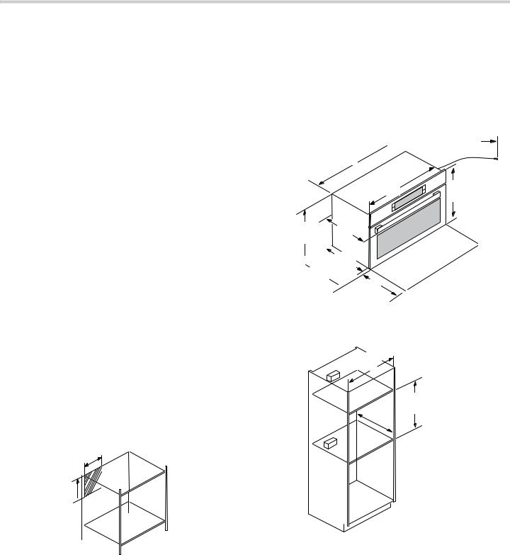
Anywhere within the shaded area the minimal distance between the appliance and the wall is 1¾ in (45 mm).
Appliances with plug connection: The outlet can be located anywhere within the shaded area.
Appliances with wire conduit connection:
For stand alone installation, the electrical connection box must be mounted to the wall inside the cabinet cavity anywhere within the shaded area.
For installation as part of a combination of various Bosch appliances, please consult the installation manual of the combo-unit.
PP

 PP
PP 
Dimensions for 30" Wall-Mounted Units
HMC80152UC
HMC80252UC
HMC80242UC
HMCP0252UC
Appliance Dimensions
+0&3 8& +0& 8& +0& 8&
 +0& 8&
èç¼ʓʘ
ë |
ʌ¼ʚ |
|
|
||
|
||
|
|
ê |
|
|
 ç¼ʚ
ç¼ʚ
 ç¼ʚ
ç¼ʚ
 ë
ë
|
PP |
|
|
Cabinet Dimensions
ê
ç¼ȫȰ


 PP
PP
NOTICE: The cabinet base must be flat and capable of supporting a weight of at least 142 lbs (64.1 kg).
6

Under counter dimensions 30” units |
Cabinet Dimensions |


|
|
|
|
|
|
|
|
|
é |
|
|
|
|
|
|
|
|
|
|
|
|
|
|
|
|
|
|
|
|
|
|
|
ê |
|
|
|
|
|
|
|
|
ë ë |
|
|
|
|
|
|
|
|
|
|
|
|
|
Flush installation 30" units |
|
|
|
|
||
7RS YLHZ |
|
|
|
|
6LGH YLHZ |
|
|
|
|
|
|
FOHDWV |
|
|
|
ê |
|
|
é |
é |
|
|
|
|
|
|
|
|
|
|
|
|
||
|
|
)OXVK LQVHW |
RSHQLQJ |
IOXVK |
||
ʎ¼ʚ |
ʎ¼ʚ |
GHSWK |
|
|
FXW RXW |
FXW RXW |
&OHDWV |
&OHDWV |
|
|
|
KHLJKW |
KHLJKW |
|
|
|
|
|||
|
|
|
|
|
|
|
|
|
|
|
|
ê |
|
ê |
|
|
|
|||
|
|
|
|
|||
é |
|
|
|
|
|
|
EDVHSODWH ʌ¼ʓʘ |
|
|||||
|
|
|
||||
|
|
|
|
0HDVXUHPHQWV LQ LQFKHV PP |
||
Flush installation also requires:
two side cleats to be attached inside the cabinet frame, recessed from the front
a 5/16" (8 mm) baseplate underneath the unit body.
Dimensions for 27” Wall-Mounted Units
HMC87152UC
Appliance Dimensions


èç¼ʓʘ
ë |
ʌ¼ʚ |
|
|
||
|
||
|
|
ê |
|
|
|
|
 ç¼ʚ
ç¼ʚ
ç¼ʚ
 ë
ë
|
PP |
ê
191 "
(488)

PP
NOTICE: The cabinet base must be flat and capable of supporting a weight of at least 142 lbs (64.1 kg).
Under counter dimensions 27” units


|
|
|
|
|
|
|
é |
|
|
|
|
|
|
|
|
|
|
|
|
|
|
|
ê |
|
|
|
|
|
|
ë ë |
|
|
|
|
|
|
|
|
|
Flush installation 27 “ units |
|
|
||
7RS YLHZ |
|
|
6LGH YLHZ |
|
|
|
|
FOHDWV |
|
|
|
ê |
é |
é |
|
|
|
|
|
|
|
|
||
|
|
)OXVK LQVHW |
RSHQLQJ |
IOXVK |
ʎ¼ʚ |
ʎ¼ʚ |
GHSWK |
FXW RXW |
FXW RXW |
&OHDWV |
&OHDWV |
|
KHLJKW |
KHLJKW |
|
|
|
||
|
|
|
|
|
|
|
|
ê |
|
ê |
|
|
||
é |
|
|
|
|
|
|
|
||
EDVHSODWH ʌ¼ʓʘ
0HDVXUHPHQWV LQ LQFKHV PP
Flush installation also requires:
two side cleats to be attached inside the cabinet frame, recessed from the front
a 5/16" (8 mm) baseplate underneath the unit body.
7
Electrical Installation - GROUNDING INSTRUCTIONS
The models stated on the front cover are either dualrated, designed to be connected to either 208/240V AC, 60 Hz, 4-wire, single-phase power supply, or rated at 120V AC, 60 Hz and use a NEMA 5-20 plug to connect to a dedicated 120 V microwave circuit.
208/240 V models may also be combined with some Bosch Built-in Ovens and can be connected directly to the combo appliance. To do this, please refer to detailed instructions with the Bosch Combination Kit.
9WARNING
When connected to a 4 or 5-wire, 120/208-Volt 3- phase power supply, the phase C conductor is not required for the operation of the appliance.
Model |
Connection |
Circuit |
|
|
|
Requirements |
|
|
|
|
|
HMCP0252UC |
4 wire conduit |
208 V, |
20 Amps |
|
cable |
60 Hz |
|
|
|
|
|
|
|
240 V, |
20 Amps |
|
|
60 Hz |
|
HMC80252UC |
4 wire conduit |
208 V, |
20 Amps |
HMC80242UC |
cable |
60 Hz |
|
|
|
240 V, |
20 Amps |
|
|
60 Hz |
|
|
|
|
|
HMC80152UC |
NEMA 5-20 |
120 V, |
20 Amps |
|
|
60 Hz |
|
HMC87152UC |
NEMA 5-20 |
120 V, |
20 Amps |
|
|
60 Hz |
|
|
|
|
|
Electrical Connection with Plug
HMC80152UC
HMC87152UC
Electrical Requirements:
a three prong grounded outlet
120 V, 60 Hz, AC only
20 Amp electrical supply with a fuse or a circuit breaker
This product must be connected to a supply circuit of the proper voltage and frequency. Wire size must conform to the requirements of the National Electric Code or the prevailing local code for this rating. The power supply cord and plug should be brought to a separate 20-amp branch circuit single grounded outlet. The outlet box should be located in the area behind the appliance (see section Cabinet Dimensions). The outlet box and supply circuit should be installed by a qualified electrician and conform to the National Electrical Code or the prevailing local code.
The voltage used must be the same as specified on this microwave oven. Using a higher voltage is dangerous and may result in a fire or oven damage. Using a lower voltage will cause slow cooking. The manufacturer is not responsible for any damages resulting from the use of the oven with any voltage other than specified.
Electrical Connection with Wire Conduit
HMC80252UC
HMC80242UC
HMCP0252UC
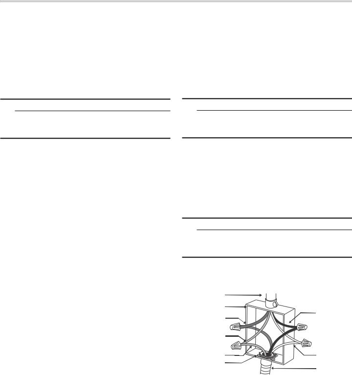
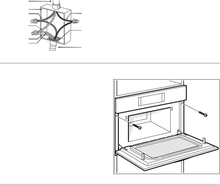
The electrical supply should be a 4-wire single-phase AC. Install a suitable conduit box (not furnished). An appropriately-sized, UL-listed conduit connector must be used to correctly attach the conduit to the junction box.
9WARNING
Local codes may vary; installation, electrical connections and grounding must comply with all applicable local codes.
If local codes permit grounding through the electrical supply neutral, connect both the white neutral wire and the bare ground wire from the oven to the white neutral electrical supply wire.
Electrical Connection
The four-wire connection is preferred, but where local codes permit, the three wire connection is also acceptable.
9WARNING
When connected to a 4 or 5-wire, 120/208-Volt 3- phase power supply, the phase C conductor is not required for the operation of the appliance.
Four-wire Connection
Ungrounded Neutral
SRZHU VXSSO\ |
|
|
MXQFWLRQ ER[ |
EODFN ZLUHV |
|
UHG ZLUHV |
||
|
||
JUHHQ RU EDUH |
|
|
ZLUH |
|
|
JUHHQ ZLUH |
ZKLWH ZLUHV |
|
8/ OLVWHG |
|
|
FRQQHFWRU |
FDEOH IURP |
|
|
RYHQ |
Connect the red oven wire to the red electrical supply wire (hot wire).
Connect the black oven wire to the black electrical supply wire (hot wire).
Connect the white neutral oven wire to the white neutral (not bare or green ground) electrical supply wire.
Connect the green ground oven wire to the bare or green ground electrical supply wire.
8
Three-wire Connection
Grounded Neutral
SRZHU VXSSO\ |
|
|
MXQFWLRQ ER[ |
EODFN ZLUHV |
|
UHG ZLUHV |
||
|
||
ZKLWH EDUH RU |
8/ OLVWHG |
|
JUHHQ ZLUH |
||
FRQQHFWRU |
||
|
||
ZKLWH ZLUH |
|
|
JUHHQ ZLUH |
FDEOH IURP |
|
|
RYHQ |
Connect red wire from oven to red wire in junction box.
Connect black wire from oven to black wire in junction box.
Connect both green ground wire and white wire from oven to white, green or bare neutral wire in junction box.
The conduit cable, where connected at the oven, swivels. Rotate conduit cable upward (or downward) and direct through hole prepared in cabinet to attach to junction box.
To maintain serviceability, the flex conduit must not be shortened and should be routed to permit temporary removal of the oven.
Install Appliance
Note: The appliance is heavy. It is advisable to install it with a second person.
NOTICE: Before installing the appliance, be sure to verify the cabinet dimensions and electrical connections.
Mount to Cabinet
1.Fully insert the appliance and center it. Do not kink the electrical cable.
2.Screw the appliance into place.
Testing Operation
1.Turn on power at the breaker.
2.For Model HMC80252UC and HMCP0252UC: Check power at junction box using a volt meter.
For 240 V installation, the reading between the red and black wires (line to line) should be 220 to 240 volts.
For 208 V installation, the reading between the red and black wires (line to line) should be 190 to 208 volts.
3.For all models: Test the oven mode.
Select the CONVECTION mode. See the Use and Care Manual for detailed operation instructions.
4.Verify that the oven light comes on and the oven begins to preheat.
5.Test the microwave:
Place a cup of water into the oven cavity. Follow the instructions in the Use and Care Manual on how to heat a beverage.
6.Verify that the oven light comes on and the water is heated.
7.If any of the tests do not result as explained above, contact Service for assistance. Otherwise, the installation is complete at this time.
9
Bosch® Support
Before Calling Service
See the Use and Care Manual for troubleshooting information. Refer to the “Statement of Limited Product Warranty” in the Use and Care Manual.
To reach a service representative, see the contact information at the front of the manual or in the following section. Please be prepared with the information printed on your product data plate prior to calling.
Data Plate
The data plate shows the model and serial number. Refer to the data plate on the appliance when requesting service.
The data plate can be found on the inside of the appliance door.
To avoid having to search for each piece of information when calling, you can enter the four items needed in the spaces provided below.
Model No.
FD-No.
Date of Purchase
Customer Service O
Keep your invoice or escrow papers for warranty validation if service is needed.
Service
We realize that you have made a considerable investment in your kitchen. We are dedicated to supporting you and your appliance so that you have many years of creative cooking.
Please don’t hesitate to contact our Customer Support Department if you have any questions or in the unlikely event that your Bosch® appliance needs service. Our service team is ready to assist you.
USA
800-944-2904 www.bosch-home.com/us/support
Canada
800-944-2904 www.bosch-home.ca/en/support
Parts and Accessories
Parts, filters, descalers, stainless steel cleaners and more can be purchased in the Bosch® eShop or by phone.
USA www.bosch-home.com/us/store
Canada
Marcone 800-482-6022 or
Reliable Parts 800-941-9217
10
 Loading...