


HBL8x50UC
Bosch HBL8x50UC, HBL57x0UC, HBL56x0UC, HBL54x0UC, HBL35x0UC Service Manual
...
SERVICE MANUAL
for
300, 500, and 800 Series
Built-in Wall Ovens
This manual contains information that is necessary for
servicing the following Bosch electric built-in wall
ovens:
HBL8x50UC, HBL57x0UC, HBL56x0UC,
HBL54x0UC, HBL35x0UC, HBL33x0UC,
HBN56x0UC, HBN54x0UC, HBN35x0UC,
HBN34x0UC, HBN3350UC
This manual is designed to be used by qualified
service personnel only. Due to the complexity and the
risk of high-voltage electrical shock, Bosch does not
recommend that customers service their own units.
Models:
HBL8x50UC, HBL57x0UC, HBL56x0UC,
HBL54x0UC, HBL35x0UC, HBL33x0UC,
HBN56x0UC, HBN54x0UC, HBN35x0UC,
HBN34x0UC, HBN3350UC

Service Manual for Bosch Built-in Wall Ovens
TABLE OF CONTENTS
1 General........................................................................................3
1.1 Models................................................................................... 3
1.2 Features and Options............................................................3
1.3 Data Plate..............................................................................4
1.4 Warranty ................................................................................4
2 Operation.....................................................................................4
2.1 Element Duty Cycles.............................................................4
2.1.1 Using Table 3 (Element Duty Cycles During Preheat)...5
2.2 Sequence of Events..............................................................5
2.3 Cooling Fans.........................................................................7
3 Component Accessibility...........................................................8
3.1 Serviceable from Front..........................................................8
3.2 Serviceable from Top............................................................8
3.3 Serviceable from Rear...........................................................8
4 Service and Repair.....................................................................8
4.1 Doors.....................................................................................8
4.1.1 Removing and Replacing the Door(s)............................8
4.2 Door Latch/Motor Assembly..................................................9
4.3 Lamps..................................................................................10
4.3.1 Replacing Lamps .........................................................10
4.4 High Temperature Cutout (HTC).........................................11
4.5 Convection Fan and Ring Element......................................11
4.6 Temperature Sensor ...........................................................12
4.6.1 Setting Temperature Offsets........................................12
4.7 Broil Element.......................................................................13
4.8 User Interface......................................................................13
4.8.1 Removing the User Interface .......................................14
4.9 PC Control Module (Relay Board).......................................15
4.10 Power Supply Module......................................................18
4.11 Halogen Light Transformer(s)..........................................18
4.12 Convection Fan Motor .....................................................18
4.13 Bake Element (Upper Oven)............................................18
4.13.1 Removing the Bake Element........................................18
4.13.2 Reinstalling the Bake Element.....................................19
4.14 Cooling Fan Motor (Upper Oven) ....................................19
5 Error Codes .............................................................................. 19
5.1 Error Code Table ................................................................ 19
5.2 Service Mode / Setting Option Code .................................. 20
5.2.1 HBL3/HBN3................................................................. 20
5.2.2 HBL5/HBN5................................................................. 21
5.2.3 HBL8............................................................................ 21
5.3 Option Codes...................................................................... 22
6 Demo Mode............................................................................... 22
7 Troubleshooting....................................................................... 22
7.1 Fault Tree Diagram............................................................. 23
7.2 Fault Tree ........................................................................... 25
7.3 Testing................................................................................ 33
8 Wiring Diagrams and Schematics.......................................... 33
8.1 Wire Color Key.................................................................... 33
8.2 Strip Diagrams.................................................................... 34
9 Additional References............................................................. 34
9.1 QuickFinder ........................................................................ 34
9.2 Technical Support............................................................... 34
Page 2 of 36

Service Manual for Bosch Built-in Wall Ovens
1 GENERAL
There are nine HBL (30”) and five HBN (27”) models in various
combinations and three colors (black, white, and stainless), included
in the 2007 Bosch 300, 500, and 800 Series Built-in Wall Oven
(BIWO) product line. These models include A (thermal), B
(convection), and C (convection with ring element) oven cavities. Two
in the series are combination models with microwaves – the
HBL57x0UC (with HMB50x0 traditional microwave) and HBL8750UC
(with HMB80x0 convection microwave).
The 800 series models are stainless steel and have a glass user
interface (touch panel) with graphical displays. 500 series models are
available in black, white, and stainless, and have ergonomic,
retractable dials. The 300 series models, also available in three color
options, have ergonomic dials. Fast preheat capability, 2-hour selfclean, telescopic racks, and up to 16 cooking modes are among the
features offered.
The control panel and door skins on the stainless models are grade
304 stainless steel.
1.1 Models
27” Ovens
HBN56x0UC Double oven with thermal/true convection
HBN54x0UC Single oven with true convection
HBN35x0UC Double oven with convection/thermal
HBN34x0UC Single oven with convection
HBN3350UC Single oven with thermal
30” Ovens
HBL8750UC Combo with true convection oven/convection micro
HBL8650UC Double oven with true convection both cavities
HBL8450UC Single oven with true convection
HBL57x0UC Combination with true convection oven /traditional micro
HBL56x0UC Double oven with true convection/thermal
HBL54x0UC Single oven with true convection
HBL34x0UC Single oven with convection
HBL33x0UC Single oven with thermal
1.2 Features and Options
Cavity configuration and features by model appear below.
Table 1 Bosch 27” 300 and 500 Series Features by Model
Table 2 Bosch 30” 300, 500, and 800 Series Features by Model
Page 3 of 36
Service Manual for Bosch Built-in Wall Ovens
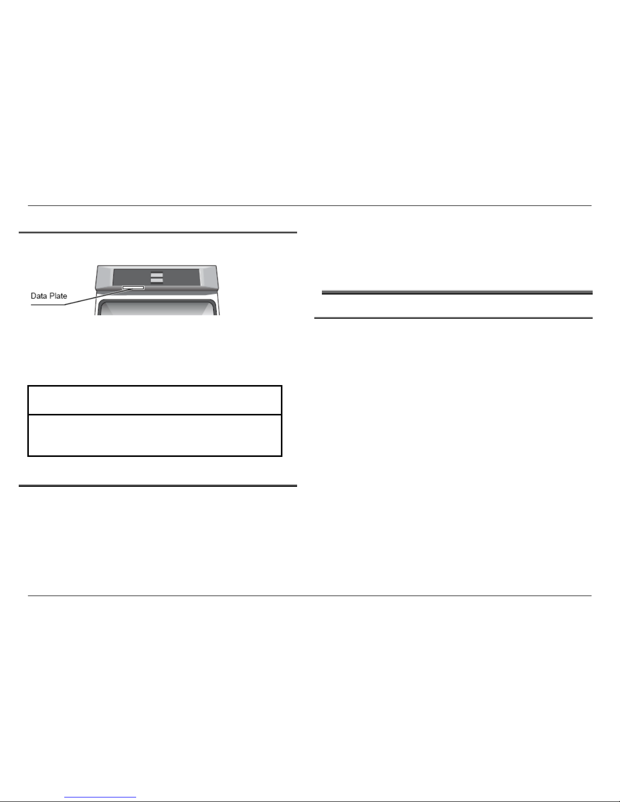
1.3 Data Plate
The data plate reflecting model number and FD number is located on
the underside of the interface control panel, as shown in Figure 1.
The first 4 positions of the FD number reflect the year/month the
product was built. FD numbers that begin with 87 were built in 2007;
88 = 2008; 89 = 2009, etc.
1.4 Warranty
The product is warranted to be free from defects in materials and
workmanship for a period of 12 months from date of purchase.
Bosch will pay for all repair labor and replacement parts found to be
defective due to materials and workmanship. Service must be
provided by a Factory Authorized Service Agency, during normal
working hours.
Bosch assumes no responsibility for any repairs made on our
products by anyone other than authorized service technicians.
Find the complete product warranty statement in the Use and Care
Manual.
Figure 1 Data plate location
2 OPERATION
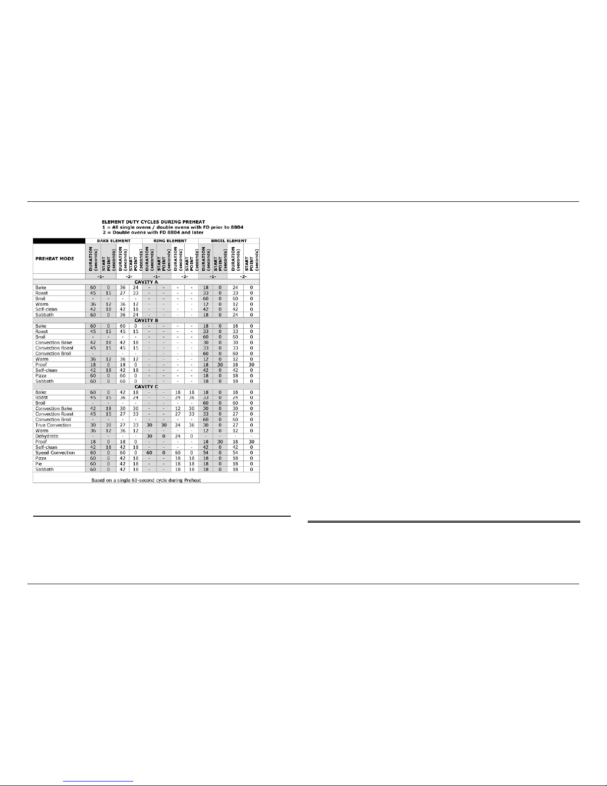
2.1 Element Duty Cycles
A new PID algorithm controls the way in which the elements cycle on
and off during each cooking mode duty cycle. Every minute, the oven
temperature is compared to the set point and a recalculation occurs,
which results in varied element cycle times rather than the standard
fixed 60-second cycle.
During Preheat, however, a 2-point control is still used and there is a
defined element on-time. The following table reflects the duration and
start point by Preheat mode, for cavity types A, B, and C.
Technicians should have ample time to troubleshoot element
problems during the ~10-minute preheat period.
NOTICE
Be prepared to provide the complete Model Number and FD
number printed on the data tag of the unit when contacting Bosch
Customer Support or Technical Support for assistance.
Page 4 of 36
Service Manual for Bosch Built-in Wall Ovens
2.1.1 Using Table 3 (Element Duty Cycles During Preheat)
In Table 3, Duration is defined as the number of seconds an
element is turned on (e.g., 12 indicates the element will be on for 12
seconds.) Start Point is defined as the point in the cycle at which the
element will turn on (e.g., 30 indicates the element will turn on in the
30
th
second of the cycle).
Using the data in the table, below is an example of how the elements
cycle on and off during a 60-second Preheat cycle in True
Convection mode (see Cavity C):
HBL8450UC built in 01/2008 (see columns labeled -1-)
Table 3 Element duty cycles during preheat by cavity type.
• Bake Element: After initial 30 seconds of the cycle, element
turns on and remains on for the final 30 seconds of the cycle.
• Ring Element: After initial 30 seconds of the cycle, element
turns on and remains on for the final 30 seconds of the cycle
(same as Bake Element).
• Broil Element: Turns on at the beginning of the cycle (0) and
remains on for the first 30 seconds of the cycle.
HBL8450UC built in 08/2008 (see columns labeled -2-)
• Bake Element: After initial 33 seconds of the cycle, element
turns on and remains on for the final 27 seconds of the cycle.
• Ring Element: After initial 36 seconds of the cycle, element
turns on and remains on for the final 24 seconds of the cycle.
• Broil Element: Turns on at the beginning of the cycle (0) and
remains on for the first 27 seconds of the cycle.
In Fast Preheat (available in cavities B and C with convection fan), the
same elements reflected in the table are used, but the broil element is
on ~10% longer, and the convection fan stays on as well.
It is important to note that during regulation (regular cooking period
that follows Preheat), different elements may be used and element
duty cycles will vary.
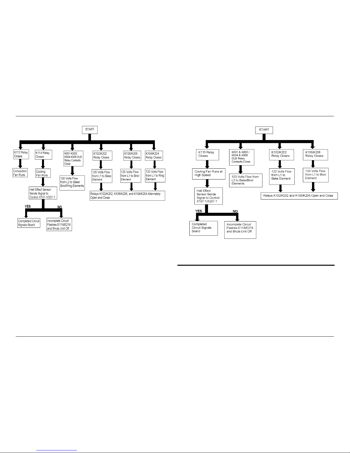
2.2 Sequence of Events
Figures 2 – 5 reflect the sequence of events which occur during
Preheat for the various cooking modes.
Page 5 of 36

Service Manual for Bosch Built-in Wall Ovens
Fi gure 3 Sequence of Events during Preheat: Convection Broil/Broil modes
Figure 2 Sequence of Events during Preheat: Convection Bake & Roast/ Bake, Roast, Warm, Proof,
Pizza, Pie, & Sabbath modes
Page 6 of 36
Service Manual for Bosch Built-in Wall Ovens
Page 7 of 36
Figure 5 Sequence of Events during Preheat: Self-clean mode
Figure 4 Sequence of Events during Preheat: True Convection
2.3 Cooling Fans
Cooling fans will run for two minutes after the oven has been shut off,
regardless of the oven temperature. After two minutes, the fan will
continue to run until the interior temperature of the cavity reaches a
maximum of 350°.
(Early models were programmed with a lower shut-off temperature,
which resulted in a longer running time for the cooling fan.)
Service Manual for Bosch Built-in Wall Ovens
3 COMPONENT ACCESSIBILITY
3.1 Serviceable from Front
Door
Door latch/motor assembly
Cavity lamps
High Temperature Cutout (HTC)
Convection ring element and convection fan assembly (except
motor)
Temperature sensor
Broil element
The user interface is serviceable from the front after sliding the oven
out from the wall ~ 4 inches.
3.2 Serviceable from Top
The PC control module (relay board) is serviceable from the top
access panel after sliding the oven out from the wall ~16 inches.
With the unit pulled completely away from the wall, the following
components are serviceable from the top after removing the top
panel:
Halogen light transformers
Terminal block
Power supply
3.3 Serviceable from Rear
With the unit pulled completely away from the wall and the back
panel(s) removed, the following components can be serviced from the
rear:
Convection fan motor
Bake element
Cooling fan(s)
4 SERVICE AND REPAIR
m
CAUTION
9 Sheet metal parts often have sharp edges. Avoid injury by
handling these parts with care.
9 Turn off the electrical power circuit to the oven at the main junction
box before servicing this unit.
9 For those checks requiring the use of electrical power, exercise
extreme care.
4.1 Doors
On double ovens, the Bosch logo is located on the lower oven outer
door glass.
30” models ending with Customer Service Index (KI) /01 were
produced with 4-pane doors. Subsequent models have 3-pane doors.
4.1.1 Removing and Replacing the Door(s)
m
CAUTION
Avoid injury when removing and replacing oven doors.
9 Be sure oven is cool enough for handling.
9 Position hinges properly (see Figure 6).
9 Grasp only by sides, not by the handle.
9 Do not force door open or closed.
9 Handle with care–door weighs ~38 pounds.
Page 8 of 36
Service Manual for Bosch Built-in Wall Ovens
To remove the door…
1. Open door completely.
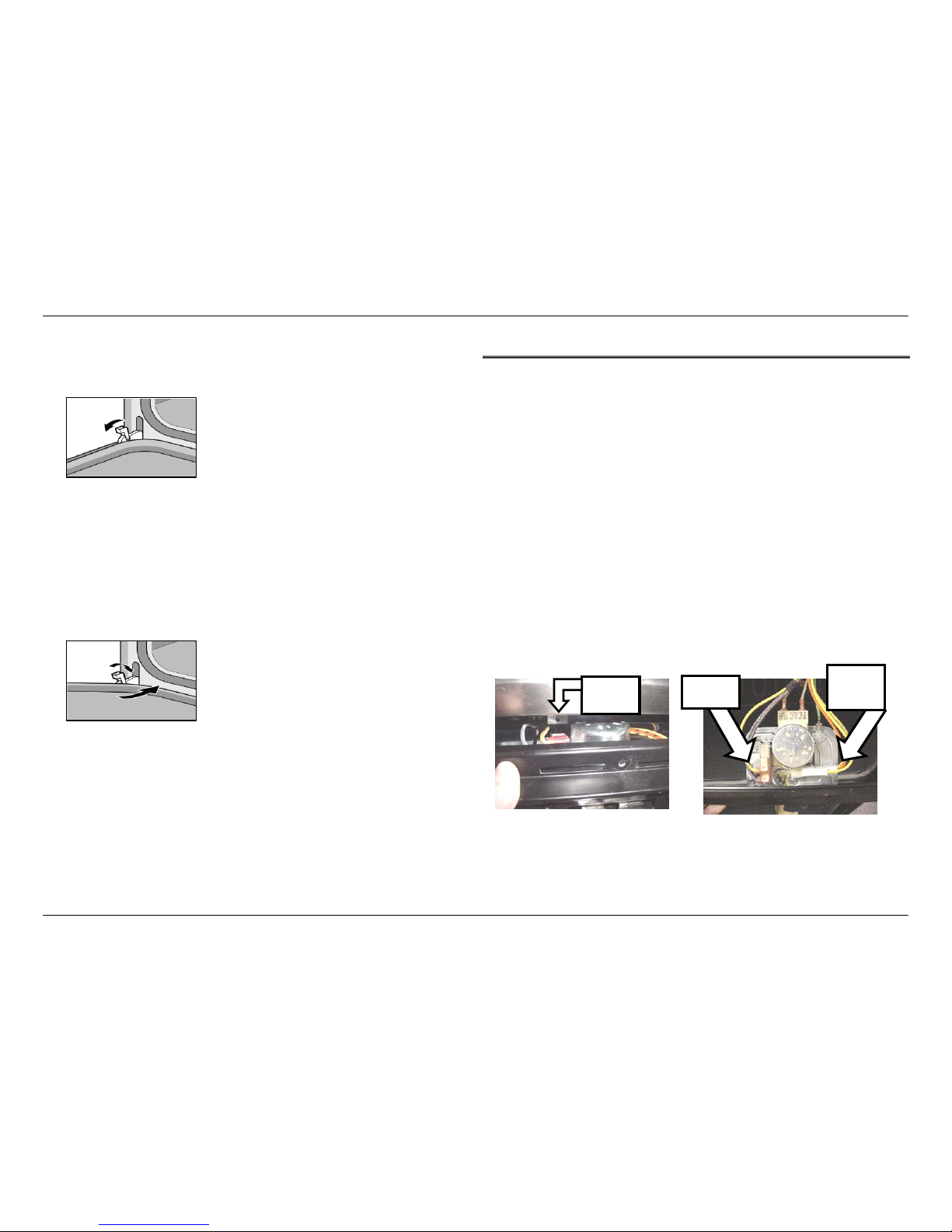
2. Flip hinge levers back to open as shown below.
3. Close door until it remains open ~6 inches.
4. Using both hands, lift door up and out.
To replace the door…
1. Position door as if it were open ~6 inches and insert hinges
into slots.
2. Open door completely.
3. Flip hinge levers forward to close as shown below.
4. Close and open door to check operation.
• Hinges should be replaced in pairs.
• The 300, 500, and 800 series ovens do not have serviceable
hinge receivers.
4.2 Door Latch/Motor Assembly
The motorized door latch (MDL) mechanism (120V 5W) has 2
switches - the door switch and the lock/unlock switch. The latch will
automatically lock when mode and temperature selectors are set to
CLEAN, and unlock when the oven cools to ~490°F. It is serviced as
an assembly.
If the latch becomes stuck in the locked position, turning the unit off
and back on will open the latch if the cavity temperature <450°. If latch
is stuck in partially locked position, press
SELF CLEAN, then ON/OFF.
The latch can be tested in Service mode.
To remove the latch/motor assembly:
Figure 6 Opening the hinge lever
1. Remove 3 T20 screws securing trim piece to frame (do not
remove 2 screws on either side of latch).
2. Pull trim forward about 1”, then slightly to the right or left to
clear the screw tab (see Figure 8).
3. Slip hands under trim and lift upper plate while sliding trim and
latch toward you.
Figure 7 Closing hinge lever
Lock/
Unlock
Switch
Door
Switch
Screw
Tab
Figure 8 Door latch/motor assembly
Page 9 of 36
Service Manual for Bosch Built-in Wall Ovens
4.3 Lamps
The operation of the cavity lights is determined by the state of the
lights, the state of the oven, and the button(s) pressed. The table
below illustrates the results after each button press.
4.3.1 Replacing Lamps
The number and type of lamps in each cavity will vary, depending on
model. Two types of bulbs are used: 10-watt, 12-volt bi-pin halogen
light bulbs or 40- (30”) or 25-watt (27”) incandescent appliance bulbs.
Current state
of lights
Current state of
oven
Key(s)
Pressed
Resulting state
of lights
Upper Lower Upper Lower Upper Lower
OFF OFF LIGHT ON ON
ON OFF LIGHT ON OFF
OFF ON LIGHT OFF ON
ON ON LIGHT ON ON
DOES NOT MATTER
UPPER+LIGHT
ON OFF
OFF OFF
DOES NOT MATTER
LOWER+LIGHT
OFF ON
OFF OFF LIGHT OFF OFF
ON OFF LIGHT OFF OFF
OFF ON LIGHT ON ON
ON ON LIGHT OFF OFF
DOES NOT MATTER
UPPER+LIGHT
OFF OFF
ON OFF
DOES NOT MATTER
LOWER+LIGHT
ON ON
OFF OFF LIGHT OFF OFF
ON OFF LIGHT ON ON
Handle all bulbs with a clean, dry cloth.
OFF ON LIGHT OFF OFF
ON ON LIGHT OFF OFF
DOES NOT MATTER
UPPER+LIGHT
ON ON
OFF ON
DOES NOT MATTER
LOWER+LIGHT
OFF OFF
OFF OFF LIGHT OFF OFF
ON OFF LIGHT OFF ON
OFF ON LIGHT ON OFF
ON ON LIGHT OFF OFF
DOES NOT MATTER
UPPER+LIGHT
OFF ON
ON ON
DOES NOT MATTER
LOWER+LIGHT
ON OFF
The lights will automatically illuminate whenever the oven door is
opened, and turn off when the door is closed.
m
CAUTION
9 Turn off power to the oven at the fuse or breaker box–light socket
is live with door open.
9 Be sure oven and lights are cool to the touch.
9 Handle glass lenses carefully.
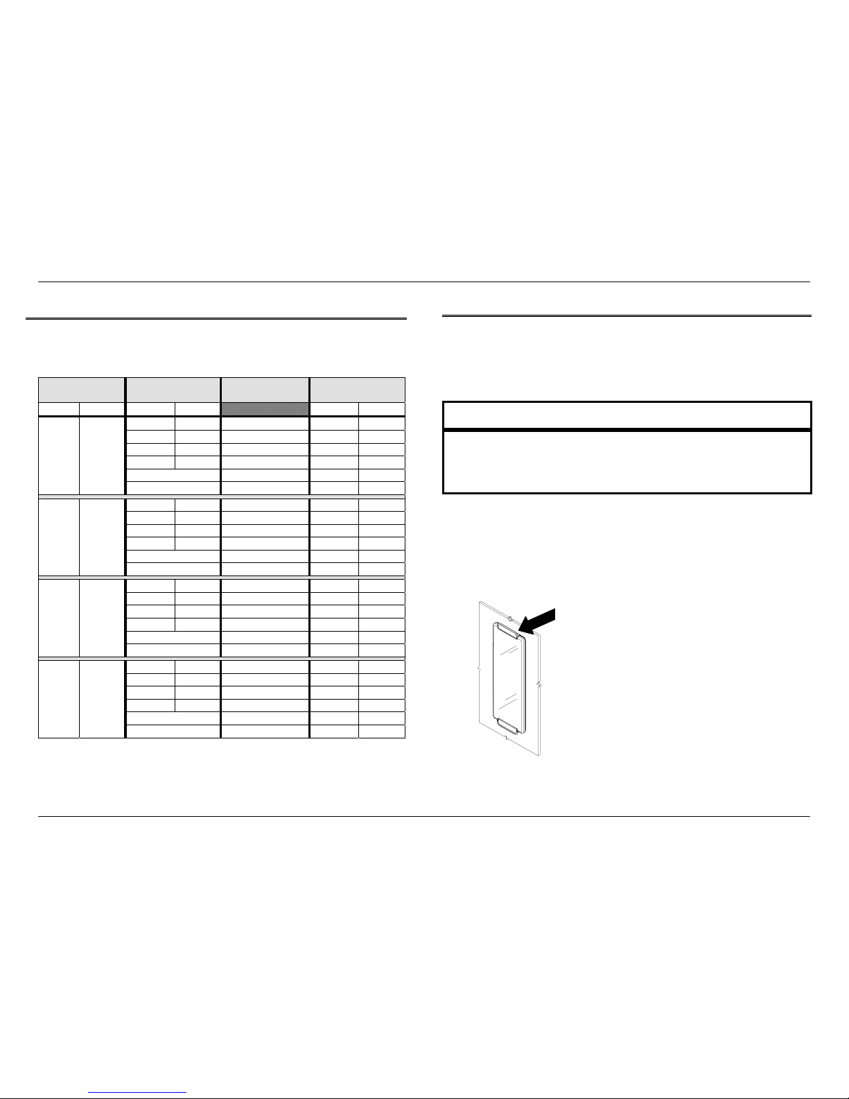
4.3.1.1 Halogen Side Lamp (Vertical-style)
1. Remove racks and rack support.
2. Firmly push the top mounting clip up and back (toward oven
wall), until it releases the glass cover.
Top
mounting
clip
Figure 9 Vertical-style side lamp
Table 4 Operation of cavity lights
Page 10 of 36
Service Manual for Bosch Built-in Wall Ovens
3. Pull the halogen bulb straight out from its socket.
4. Using a clean, dry cloth, insert the new bulb.
5. Reinsert the bottom of the glass cover (smooth side out) into
the bottom clip, and firmly push the top of the cover into the
upper clip until it snaps into place.
6. Restore power to the unit.
4.3.1.2 Halogen Side Lamp (Horizontal-style)
1. Remove racks and rack support.
2. Slide tip of flat-blade screwdriver between fixing clip and lamp
housing, while supporting lens cover along bottom edge.
3. Gently twist screwdriver to loosen the lens cover.
4. Remove cover and fixing clip.
5. Grasp halogen bulb and pull it straight out from its socket.
6. Using a clean, dry cloth, insert new bulb into socket.
7. Reinsert lens cover into the holder clip and gently push back
until fixing clip snaps into place.
8. Restore power to the unit.
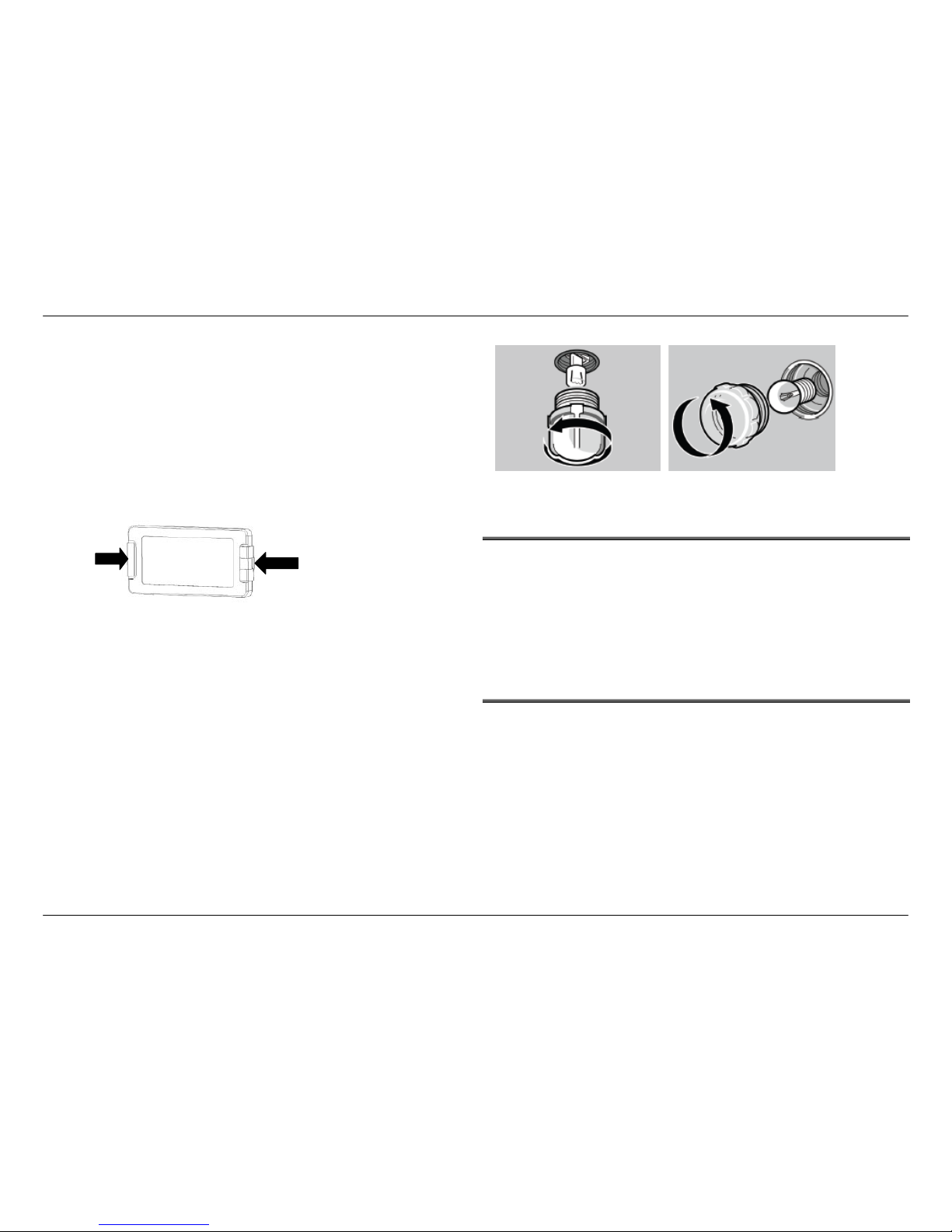
4.3.1.3 Halogen Ceiling Lamp and Incandescent Cavity Lamp
1. Unscrew glass cover.
2. Pull halogen bulb straight out of its socket, or unscrew
appliance bulb.
3. Using a clean, dry cloth, insert the new bulb.
4. Replace the glass cover.
5. Restore power to the unit.
Figure 11 Round halogen ceiling lamp (L); traditional lamp with 40W or 25W appliance
bulb (R).
Slide screwdriver
between fixing clip
and lamp housing.
Figure 10 Horizontal-style side lamp
Holder
clip
4.4 High Temperature Cutout (HTC)
The HTC is a normally closed switch which will interrupt the relay
supply voltage in the event of a high temperature event caused by a
malfunctioning control module.
The HTC is located in the plenum, behind and to the left of the MDL.
Although it cannot be easily removed or replaced, a screwdriver can
be used to reach the reset button located on the top center of the HTC
after the latch plate has been removed.
4.5 Convection Fan and Ring Element
All models except the HBL33/HBN33 and the lower cavity of the
HBL56/HBN56 and HBL35/HBN35 models, which have a thermal
oven cavity, are configured with convection capabilities in the upper
and/or lower ovens. The HBL34/HBN34 and HBL35/HBN35 models
have a convection fan only, and the remaining models with convection
cavities have both a convection fan and a convection (also called a
“ring” or “3
rd”
) element, which gives the ovens true (or genuine
European) convection capability.
Depending on the cooking mode selected, the fan may be used, with
or without the ring element, to circulate heat evenly throughout the
cavity in various cooking modes.
Page 11 of 36
 Loading...