


3-500
Bosch 3-500, 8-1100, 30-290, 40-220, 30-300 Operating/safety Instructions Manual
...
1
IMPORTANT: IMPORTANT : IMPORTANTE:
Read Before Using Lire avant usage Leer antes de usar
For English Version Version française Versión en español
See page 2 Voir page 18 Ver la página 34
Operating/Safety Instructions
Consignes de sécurité/d’utilisation
Instrucciones de funcionamiento y seguridad
1-877-BOSCH99 (1-877-267-2499) www.boschtools.com
Call Toll Free for
Consumer Information
& Service Locations
Pour obtenir des informa-
tions et les adresses de nos
centres de
service après-vente,
appelez ce numéro gratuit
Llame gratis para
obtener información
para el consumidor y
ubicaciones de servicio
30-300
40-220
50-210
60-120
23-380
30-290
3-500
8-1100
15-500
160992A3VR.indb 1 3/7/17 12:22 PM

2
Read all safety warnings and all instructions. Failure to follow the warnings and instructions may result in electric shock, fire and/or serious injury.
SAVE ALL WARNINGS AND INSTRUCTIONS FOR FUTURE REFERENCE
The term “power tool” in the warnings refers to your mains-operated (corded) power
tool or battery-operated (cordless) power tool.
Work area safety
Keep work area clean and well lit. Cluttered
or dark areas invite accidents.
Do not operate power tools in explosive
atmospheres, such as in the presence of
flammable liquids, gases or dust. Power
tools create sparks which may ignite the dust
or fumes.
Keep children and bystanders away while
operating a power tool. Distractions can
cause you to lose control.
Electrical safety
Power tool plugs must match the outlet. Never modify the plug in any way. Do
not use any adapter plugs with earthed
(grounded) power tools. Unmodified plugs
and matching outlets will reduce risk of electric shock.
Avoid body contact with earthed or
grounded surfaces such as pipes, radiators, ranges and refrigerators. There is an
increased risk of electric shock if your body is
earthed or grounded.
Do not expose power tools to rain or wet
conditions. Water entering a power tool will
increase the risk of electric shock.
Do not abuse the cord. Never use the cord
for carrying, pulling or unplugging the
power tool. Keep cord away from heat, oil,
sharp edges or moving parts. Damaged or
entangled cords increase the risk of electric
shock.
When operating a power tool outdoors,
use an extension cord suitable for outdoor
use. Use of a cord suitable for outdoor use
reduces the risk of electric shock.
If operating a power tool in a damp location
is unavoidable, use a Ground Fault Circuit
Interrupter (GFCI) protected supply. Use of
an GFCI reduces the risk of electric shock.
Personal safety
Stay alert, watch what you are doing and
use common sense when operating a power tool. Do not use a power tool while you
are tired or under the influence of drugs,
alcohol or medication. A moment of inatten-
tion while operating power tools may result in
serious personal injury.
Use personal protective equipment. Always wear eye protection. Protective equip-
ment such as dust mask, non-skid safety
shoes, hard hat, or hearing protection used
for appropriate conditions will reduce personal
injuries.
Prevent unintentional starting. Ensure the
switch is in the off-position before connecting to power source and / or battery
pack, picking up or carrying the tool. Carry-
ing power tools with your finger on the switch
or energizing power tools that have the switch
on invites accidents.
Remove any adjusting key or wrench before turning the power tool on. A wrench
or a key left attached to a rotating part of the
power tool may result in personal injury.
Do not overreach. Keep proper footing and
balance at all times. This enables better con-
trol of the power tool in unexpected situations.
Dress properly. Do not wear loose clothing or jewelry. Keep your hair, clothing
and gloves away from moving parts. Loose
clothes, jewelry or long hair can be caught in
moving parts.
If devices are provided for the connection
of dust extraction and collection facilities,
ensure these are connected and properly
used. Use of dust collection can reduce dust-
related hazards.
Power tool use and care
Do not force the power tool. Use the correct power tool for your application. The
correct power tool will do the job better and
safer at the rate for which it was designed.
Do not use the power tool if the switch
does not turn it on and off. Any power tool
that cannot be controlled with the switch is
dangerous and must be repaired.
Disconnect the plug from the power source
and/or the battery pack from the power tool
General Power Tool Safety Warnings
160992A3VR.indb 2 3/7/17 12:22 PM

3
before making any adjustments, changing
accessories, or storing power tools. Such
preventive safety measures reduce the risk of
starting the power tool accidentally.
Store idle power tools out of the reach of
children and do not allow persons unfamiliar with the power tool or these instructions to operate the power tool. Power tools
are dangerous in the hands of untrained users.
Maintain power tools. Check for misalignment or binding of moving parts, breakage
of parts and any other condition that may
affect the power tool’s operation. If damaged, have the power tool repaired before
use. Many accidents are caused by poorly
maintained power tools.
Keep cutting tools sharp and clean. Prop-
erly maintained cutting tools with sharp cutting
edges are less likely to bind and are easier to
control.
Use the power tool, accessories and tool
bits etc. in accordance with these instructions, taking into account the working conditions and the work to be performed. Use
of the power tool for operations different from
those intended could result in a hazardous
situation.
Battery tool use and care
Recharge only with the charger specified
by the manufacturer. A charger that is suit-
able for one type of battery pack may create
a risk of fire when used with another battery
pack.
Use power tools only with specifically designated battery packs. Use of any other bat-
tery packs may create a risk of injury and fire.
When battery pack is not in use, keep it
away from other metal objects like paper
clips, coins, keys, nails, screws, or other
small metal objects, that can make a connection from one terminal to another.
Shorting the battery terminals together may
cause burns or a fire.
Under abusive conditions, liquid may be
ejected from the battery; avoid contact.
If contact accidentally occurs, flush with
water. If liquid contacts eyes, additionally
seek medical help. Liquid ejected from the
battery may cause irritation or burns.
Service
Have your power tool serviced by a qualified repair person using only identical replacement parts. This will ensure that the
safety of the power tool is maintained.
Safety Rules for Industrial Cordless Angle Wrenches
Hold power tool by insulated gripping
surfaces, when performing an operation
where the fastener may contact hidden
wiring or its own cord. Fasteners contacting
a “live” wire may make exposed metal parts of
the power tool “live” and could give the operator an electric shock.
Use appropriate detectors to determine
if utility lines are hidden in the work area
or call the local utility company for assistance. Contact with electric lines can lead to
fire and electric shock. Damaging a gas line
can lead to explosion. Penetrating a water line
causes property damage.
Switch off the power tool immediately
when the tool insert jams. Be prepared for
high reaction torque that can cause kickback. The tool insert jams when:
— the power tool is subject to overload or
— it becomes wedged in the workpiece.
Hold the tool with a firm grip. High reaction
torque can briefly occur while driving in and
loosening screws.
Secure the workpiece. A workpiece clamped
with clamping devices or in a vice is held more
secure than by hand.
Always wait until the tool has come to a
complete stop before placing it down. The
tool insert can jam and lead to loss of control
over the power tool.
Before any work on the tool (e. g., maintenance, tool change, etc.) as well as during
transport and storage, set the rotational
direction switch to the centre position. Un-
intentional actuation of the On/Off switch can
lead to injuries.
Avoid unintentional switching on. Ensure
the On/Off switch is in the off position before inserting battery pack. Carrying the
power tool with your finger on the On/Off
switch or inserting the battery pack into power
tools that have the switch on invites accidents.
Use only flawless tool bits that are not
worn. Defective tool bits can break, for exam-
ple, and cause injury or damage.
When working with an application tool, pay
160992A3VR.indb 3 3/7/17 12:22 PM

4
Additional Safety Warnings
Some dust created by
power sanding, sawing,
grinding, drilling, and other construction
activities contains chemicals known to
cause cancer, birth defects or other reproductive harm. Some examples of these
chemicals are:
• Lead from lead-based paints,
• Crystalline silica from bricks and cement and
other masonry products, and
• Arsenic and chromium from chemically-treated lumber.
Your risk from these exposures varies, depending on how often you do this type of work.
To reduce your exposure to these chemicals:
work in a well ventilated area, and work with
approved safety equipment, such as those
dust masks that are specially designed to filter
out microscopic particles.
attention that the application tool is firmly
seated on the tool holder. When the applica-
tion tool is not firmly connected with the tool
holder, it can come loose again and not be
controlled.
Be careful when long screws are screwed
in. Depending on the type of screw and the
tool bit used, there is a danger of slipping.
Long screws are often difficult to control and
the danger exists that the tool bit may slip off
the fastener head and cause injury.
Pay attention to the direction of rotation
that is set before switching on the power
tool. For example, when a screw is to be loos-
ened and the direction of rotation is set so
that the screw is tightened, this can lead to a
strong torque reaction of the power tool.
Do not use this tool as a drill. Tools equipped
with shutoff clutches are not designed for drilling applications. The clutch can shut off automatically and without warning.
Do not open the battery. Danger of shortcircuiting.
Protect the battery against heat, e. g.,
against continuous intense sunlight, fire,
water, and moisture. Danger of explosion.
In case of damage and improper use of the
battery, vapours may be emitted. Ventilate
the area and seek medical help in case of
complaints. The vapours can irritate the re-
spiratory system.
Use the battery only in conjunction with
your Bosch power tool. This measure alone
protects the battery against dangerous overload.
Use only original Bosch batteries with the
voltage listed on the nameplate of your
power tool. When using other batteries, e.g.
imitations, reconditioned batteries or other
brands, there is danger of injury as well as
property damage through exploding batteries.
The battery can be damaged by pointed
objects such as nails or screwdrivers or
by force applied externally. An internal short
circuit can occur and the battery can burn,
smoke, explode or overheat.
160992A3VR.indb 4 3/7/17 12:22 PM

5
Symbols
IMPORTANT: Some of the following symbols may be used on your tool. Please study them and
learn their meaning. Proper interpretation of these symbols will allow you to operate the tool
better and safer.
Symbol Name Designation/Explanation
V Volts Voltage (potential)
A Amperes Current
Hz Hertz Frequency (cycles per second)
W Watt Power
kg Kilograms Weight
min Minutes Time
s Seconds Time
⌀
Diameter Size of drill bits, grinding wheels, etc.
n
0
No load speed Rotational speed, at no load
n Rated speed Maximum attainable speed
.../min Revolutions or reciprocation per min-
ute
Revolutions, strokes, surface speed, orbits etc. per minute
0 Off position Zero speed, zero torque...
1, 2, 3, ...
I, II, III,
Selector settings Speed, torque or position settings. Higher
number means greater speed
Infinitely variable selector with off Speed is increasing from 0 setting
Arrow Action in the direction of arrow
Alternating current Type or a characteristic of current
Direct current Type or a characteristic of current
Alternating or direct current Type or a characteristic of current
Class II construction Designates Double Insulated Construc-
tion tools.
Earthing terminal Grounding terminal
Warning symbol Alerts user to warning messages
Li-ion RBRC seal Designates Li-ion battery recycling pro-
gram
Ni-Cad RBRC seal Designates Ni-Cad battery recycling pro-
gram
Read manual symbol Alerts user to read manual
Wear eye protection symbol Alerts user to wear eye protection
160992A3VR.indb 5 3/7/17 12:22 PM
6
Symbols (continued)
IMPORTANT: Some of the following symbols may be used on your tool. Please study them and
learn their meaning. Proper interpretation of these symbols will allow you to operate the tool
better and safer.
This symbol designates that this tool is listed by Underwriters Laboratories.
This symbol designates that this component is recognized by Underwriters Laboratories.
This symbol designates that this tool is listed by Underwriters Laboratories, to United States and Canadian
Standards.
This symbol designates that this tool is listed by the Canadian Standards Association.
This symbol designates that this tool is listed by the Canadian Standards Association, to United States and Canadian Standards.
This symbol designates that this tool is listed by the Intertek Testing Services, to United States and Canadian
Standards.
This symbol designates that this tool complies to NOM
Mexican Standards.
This symbol designates that this tool complies with CEC
California Energy Commision energy efficiency requirements.
160992A3VR.indb 6 3/7/17 12:22 PM
7
9
13
11 10
4
5
6
28
7 8
12
1
2
3
7 8
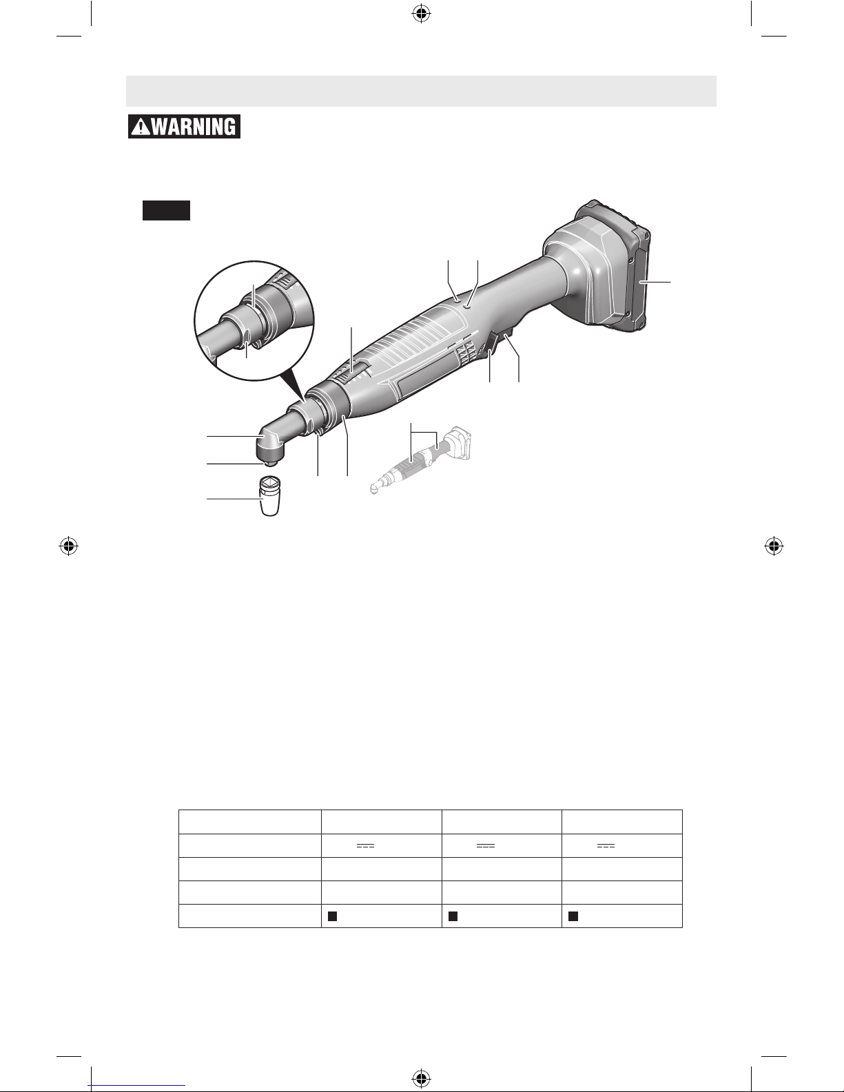
Functional Description and Specifications
Disconnect battery pack from tool before making any assembly, ad-
justments or changing accessories. Such preventive safety measures
reduce the risk of starting the tool accidentally.
Cordless Angle Wrench
Fig. 1a
Model number 3-500 8-1100 15-500
Voltage rating 18V
18V 18V
No load speed n
0
50-520/min 110-1100/min 50-520/min
Torque 0.7-3 Nm 2-8 Nm 2-15 Nm
Angle head
3/8" 3/8" 3/8"
Battery Packs/Chargers
Please refer to the Charger Manual included with your tool.
NOTE: For tool specifications refer to the nameplate on your tool.
1. Tool socket*
2. Square drive*
3. Angle head*
4. Spanner flats on the angle head flange*
5. Spanner flats on the sleeve nut
6. Torque setting window/cover
7. LED indicator, tightening control
8. Battery charge status indicator
9. Battery pack*
10. On/Off switch
11. Rotational direction switch
12. LED holder
13. Worklight
28. Protective covers
* Accessories shown or described are not
part of the standard delivery scope of the
product. A complete overview of accessories can be found in our accessories program.
160992A3VR.indb 7 3/7/17 12:22 PM
8
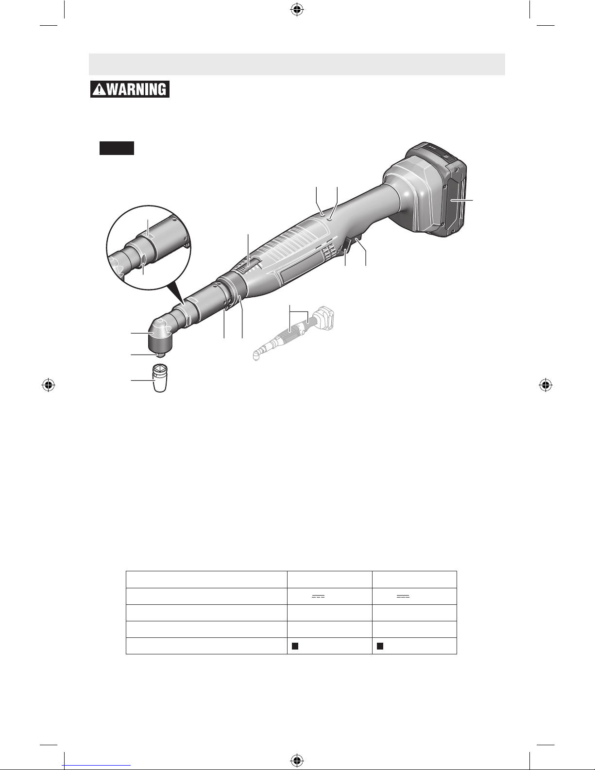
Functional Description and Specifications
Disconnect battery pack from tool before making any assembly, ad-
justments or changing accessories. Such preventive safety measures
reduce the risk of starting the tool accidentally.
Cordless Angle Wrench
Fig. 1b
Model number 23-380 30-290
Voltage rating 18V
18V
No load speed n
0
38-380/min 29-290/min
Torque 10-23 Nm 10-30 Nm
Angle head
3/8" 3/8"
Battery Packs/Chargers
Please refer to the Charger Manual included with your tool.
NOTE: For tool specifications refer to the nameplate on your tool.
9
9
9
13
11 10
4
5
4
5
6
28
7 8
12
1
2
3
1
2
3
6
6
7 8
7 8
13
11 10
12
28
1. Tool socket*
2. Square drive*
3. Angle head*
4. Spanner flats on the angle head flange*
5. Spanner flats on the sleeve nut
6. Torque setting window/cover
7. LED indicator, tightening control
8. Battery charge status indicator
9. Battery pack*
10. On/Off switch
11. Rotational direction switch
12. LED holder
13. Worklight
28. Protective covers
* Accessories shown or described are not
part of the standard delivery scope of the
product. A complete overview of accessories can be found in our accessories program.
160992A3VR.indb 8 3/7/17 12:22 PM
9
9
9
9
13
11 10
4
5
4
5
6
28
7 8
12
1
2
3
1
2
3
1
2
3
6
6
7 8
7 8
13
11 10
12
13 12
11 10
28
28
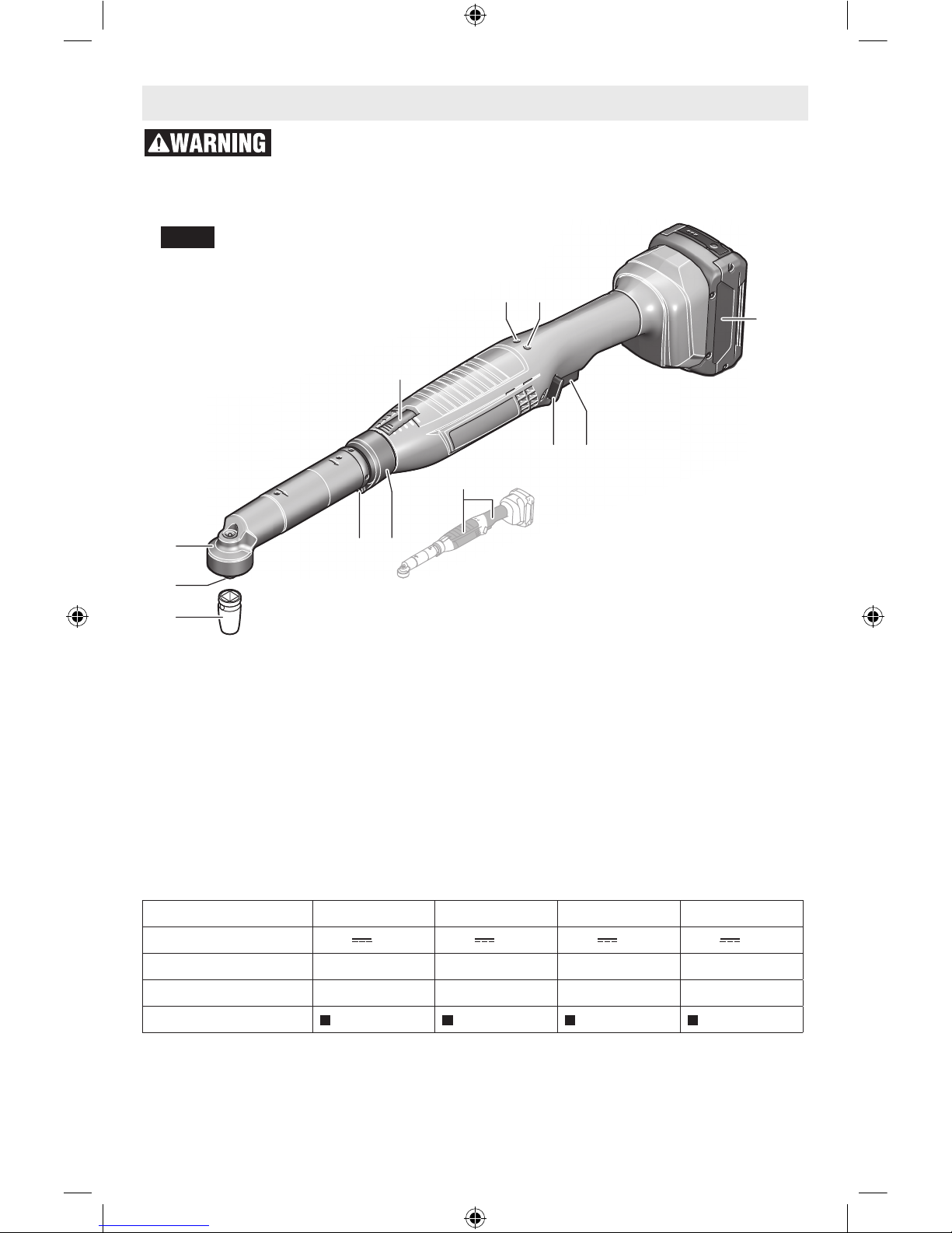
Functional Description and Specifications
Disconnect battery pack from tool before making any assembly, ad-
justments or changing accessories. Such preventive safety measures
reduce the risk of starting the tool accidentally.
Cordless Angle Wrench
Fig. 1c
Model number 30-300 40-220 50-210 60-120
Voltage rating 18V
18V 18V 18V
No load speed n
0
30-300/min 22-220/min 21-180/min 12-120/min
Torque 10-30 Nm 15-40 Nm 15-50 Nm 20-60 Nm
Angle head
3/8" 3/8" 3/8" 3/8"
Battery Packs/Chargers
Please refer to the Charger Manual included with your tool.
NOTE: For tool specifications refer to the nameplate on your tool.
1. Tool socket*
2. Square drive*
3. Angle head*
6. Torque setting window/cover
7. LED indicator, tightening control
8. Battery charge status indicator
9. Battery pack*
10. On/Off switch
11. Rotational direction switch
12. LED holder
13. Worklight
28. Protective covers
* Accessories shown or described are not
part of the standard delivery scope of the
product. A complete overview of accessories can be found in our accessories program.
160992A3VR.indb 9 3/7/17 12:22 PM
10
Disconnect battery pack
from tool before making
any assembly, adjustments or changing
accessories. Such preventive safety mea-
sures reduce the risk of starting the tool accidentally.
Recharge only with the
charger specified for the
Bosch recommended batteries. For specific charging instructions, read the operator’s manual supplied with your charger
and battery. Failure to follow the warnings
and instructions may result in electric shock,
fire and/or serious injury.
Note: The battery is supplied partially
charged. To ensure full capacity of the battery,
completely charge the battery in the battery
charger before using your power tool for the
first time.
The lithium-ion battery can be charged at any
time without reducing its service life. Interrupting the charging procedure does not damage
the battery.
The lithium ion battery is protected against
deep discharging by the “Electronic Cell Protection (ECP)”. When the battery is empty, the
tool is switched off by means of a protective
circuit: The drive socket or bit no longer rotates.
Do not continue to press
the On/Off switch after
the tool has been automatically switched
off. The battery can be damaged.
The battery is equipped with a NTC temperature control which allows charging only within
a temperature range of between 0 °C and 45
°C (32 and 113 °F). A long battery service life
is achieved in this manner.
Observe the notes for disposal.
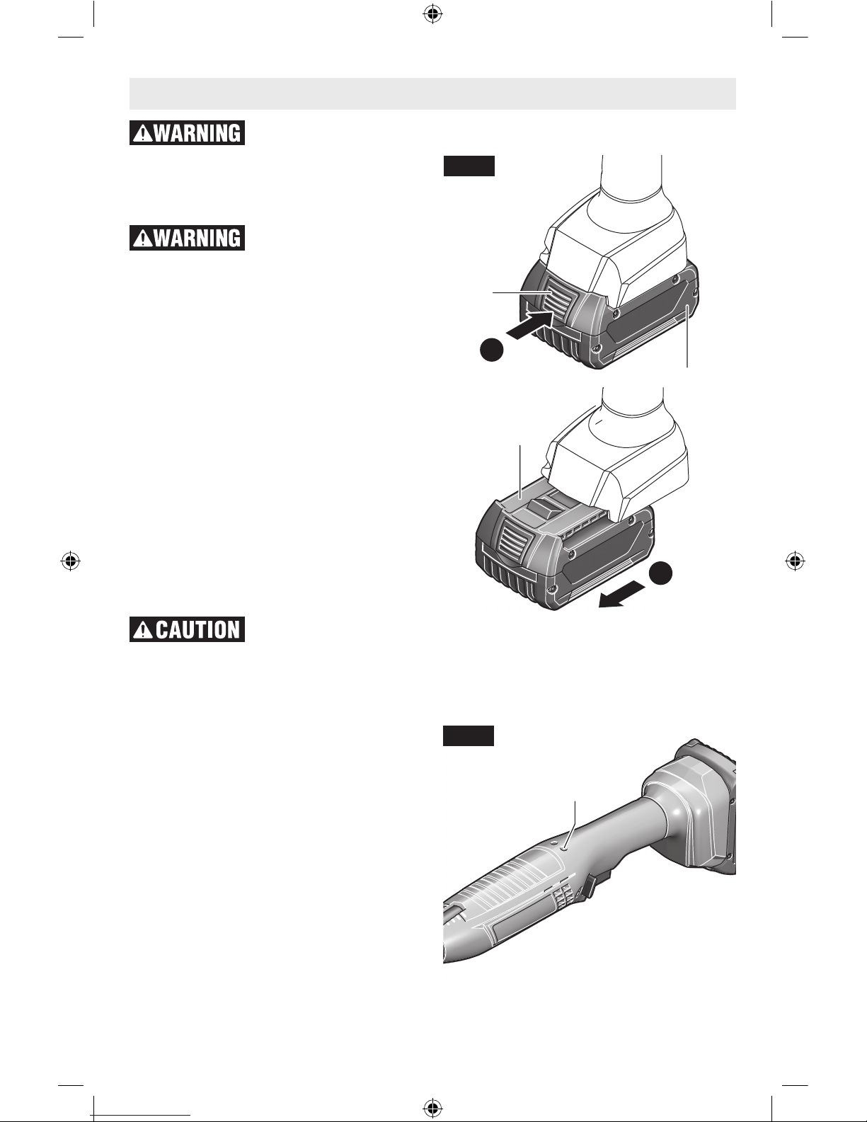
RELEASING AND INSERTING BAT-
TERY PACK
The battery 9 is equipped with two locking levels that should prevent the battery from falling
out when pushing the battery unlocking button
14 unintentionally (Fig. 2). As long as the battery is inserted in the power tool, it is held in
position by means of a spring.
– To remove the battery 9, press the unlock-
ing button 14 and pull out the battery toward
the front (Fig. 2). Do not exert any force.
– To insert battery, align battery and slide bat-
tery pack into tool until it locks into position.
Do not force.
BATTERY CHARGE STATUS
INDICATION (YELLOW LED)
Your tool is equipped with charge status indicator light 8 (Fig. 3). The indicator lights shows
the charge status of the battery
Assembly
9
9
14
2
1
Fig. 2
8
Fig. 3
160992A3VR.indb 10 3/7/17 12:22 PM

11
Battery charge
status indication
Meaning
Flashing light +
audio signal
Battery Charging:
Only 6 –8 more
screwdriving operations possible.
Continuous light Capacity no longer
sufficient for a new
screwdriving operation or the tool was
subject to overload.
The tool can no longer be switched on.
– Remove the battery and replace
with a fully charged
one.
Flashing light The tool is over-
heated and out of
operation:
– Before restarting
the operation of the
tool, wait until the
flashing automatically stops after a
short period.
OPERATING AND STORAGE ENVI-
RONMENT
The device is suitable exclusively for operation
at enclosed work sites.
For proper operation, the allowable ambient
temperature should be between 0 °C and +45
°C (32 and 113 °F) at an allowable relative humidity between 20 and 95 %, free of moisture
condensation.
SUSPENSION DEVICE
With the utility clip 15, the tool can be attached
to a suspension device.
– Fasten the utility clip 15 to the tool by en-
gaging it into the fastening slots 16 (Fig 4).
Depending on the tool’s centre of gravity, either the front or rear slots can be used.
Regularly check the condition of the utility clip
and the hook of the suspension device.
ADJUSTING THE WORKLIGHT
– Press off the marking ring 17 with a thin
screwdriver blade, a knife, or similar (Fig. 5).
– Using snap-ring pliers, slide the snap ring
18 toward the rear onto the housing shell.
The two shell halves of the LED holder 12,
which enclose the worklight 13, can now be
adjusted to any desired position.
– Pay attention not to damage the worklight
cable and, without kinking or bending it,
slide it into the cavity 19 intended for it in
the housing shell.
– Enclose the worklight 13 again with the two
housing shells of LED holder 12.
– Press the snap ring 18 and the marking ring
17 back to their initial positions.
16
15
Fig. 4
13 12
19
17 18
12
Fig. 5
160992A3VR.indb 11 3/7/17 12:22 PM
12
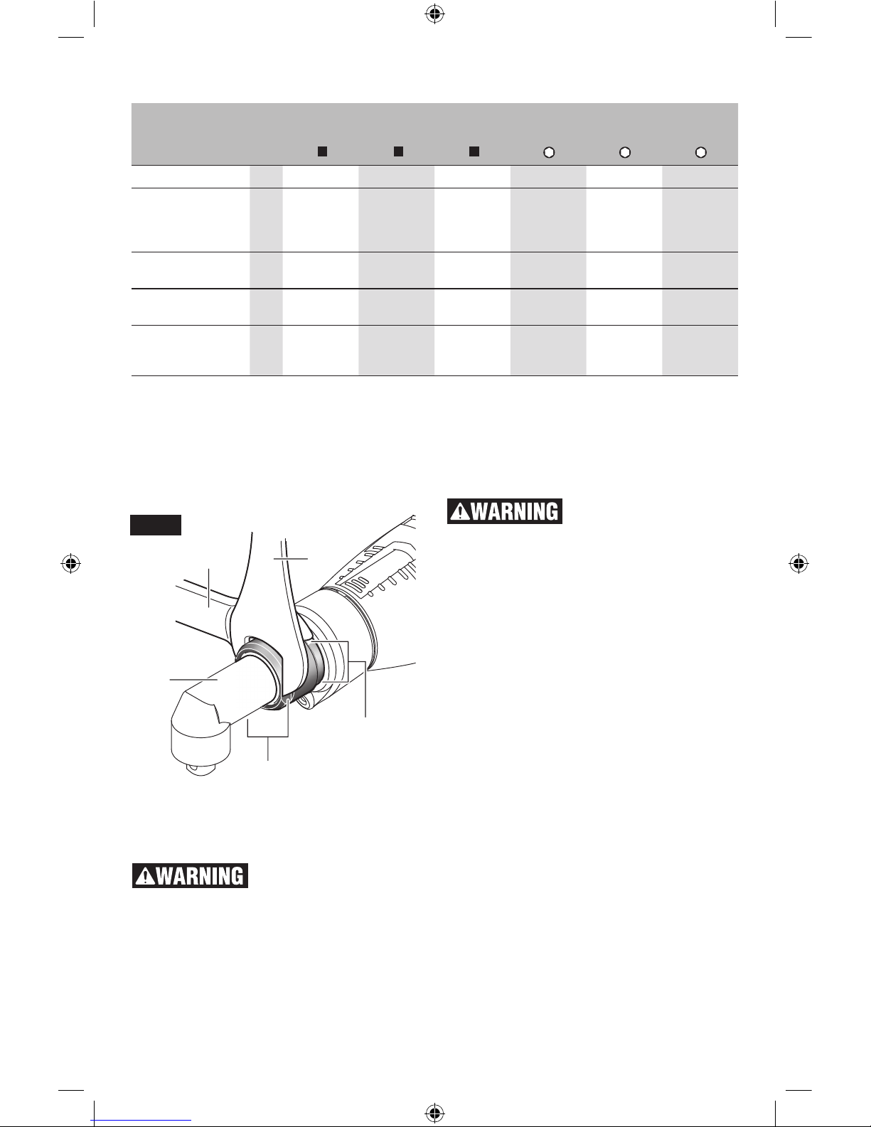
MOUNTING THE ANGLE HEAD
Applies for the following types: ANGLE
EXACT ION 3-500, 8-1100, 15-500, 23-380,
30-290.
On these industrial cordless angle wrenches,
a fitting angle head (see “ANGLE HEADS”,)
has to be mounted first.
– Hold the power tool with the open-end
spanner 21 by the spanner flats 4 of the
angle head flange (Fig. 6).
Never clamp the tool by
the housing shells!
– Mount the angle head 3 onto the flange
in the requested position and tighten the
sleeve nut with the open-end spanner 20
via the spanner flats 5.
Hold the angle head flange with the open-end
spanner 21 to prevent turning.
ADJUSTING THE ANGLE HEAD
The angle head 3 can be adjusted to a total of
eight positions.
– Hold the power tool with the open-end
spanner 21 by the spanner flats 4 of the
angle head flange.
Never clamp the tool by
the housing shells!
– Loosen the sleeve nut with the open-end
spanner 20 by the spanner flats 5. Adjust
the angle head 3 in 45° steps to the desired
position and retighten the sleeve nut again
with the open-end spanner 20 by the spanner flats 5. Hold the angle head flange with
the open-end spanner 21 to prevent turning.
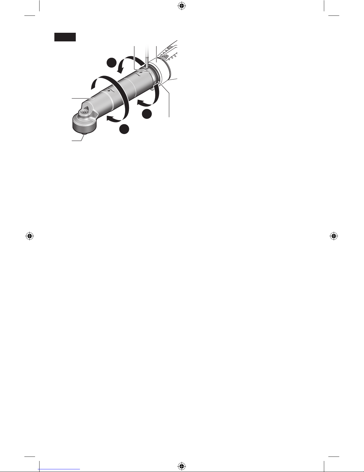
ADJUSTING AND REMOVING THE
ANGLE HEAD
Applies for the following types: ANGLE EX-
ACT ION 30-300, 40-220, 50-210, 60-120.
The angle head 3 with tool bit holder 2 can
be continuously adjusted around 360° (Fig. 7).
– Loosen the lock nut 22 by inserting an ap-
propriate tool into an opening of the lock nut
and turning the lock nut in the direction of
the arrow a (left thread).
– Fix the angle head 3 in this position by turn-
ing the lock nut 22 in the direction of the
arrow c against the angle head. Tighten the
lock nut 22 with a tightening torque of max.
50 Nm again.
– Turn the angle head 3 in arrow direction b
until the desired work angle is reached, but
not more than once by 360°.
The angle head 3 can also be removed completely, e. g. when it is required to replace the
20
21
3
4
5
Fig. 6
Angle head Straight
drive head
1/4" 3/8" 3/8"
1/4" QC 1/4" QC 1/4"
Bosch part number
0607453617 0607453620 0607451618 0607453618 0607453630 0607453 631
Maximum torque,
hard screwdriving
application according
to ISO5393 Nm 20 25 30 20 20 6
Tightening torque at
the flange Nm 20 20 25 20 20 10
Accessories for
ANGLE EXACT ION 15-500 15-500 30-300 15-500 15-500 15-500
Weight according
to EPTA-Procedure
01/2003 kg 0.2 0.2 0.2 0.2 0.2 0.2
ANGLE HEADS
160992A3VR.indb 12 3/7/17 12:22 PM
13
marking ring 17 by one with another colour or
to adjust the worklight. Adjust the worklight to
the desired position first (see “Adjusting the
Worklight”, page 11) before adjusting the angle
head.
– Loosen the lock nut 22 by inserting an ap-
propriate tool into an opening of the lock nut
and turning the lock nut in the direction of
the arrow a (left thread).
– Unscrew the angle head 3 in arrow direction
b until it can be removed.
– Unscrew the lock nut 22 from the motor
housing 23 in arrow direction a.
Now, the marking ring can be exchanged or
the worklight can be adjusted.
– Turn the lock nut 22 in arrow direction c
onto the motor housing 23 and screw on the
angle head again turning in arrow direction
b.
– Lock the angle nutrunner head by screwing
the lock nut 22 in arrow direction c.
– Retighten lock nut 22 again with a tighten-
ing torque of approx. 50 Nm.
CONFIGURING THE POWER TOOL
With the BOSCH EXACT Configurator software, different power tool settings (e. g.,
speed, driving stages, repeat protection) can
be configured. For this, the power tool must
be connected to a PC via the USB data port.
Note: Observe all safety warnings and instructions in the software instruction manual.
23
3
2
22
17
b
a
c
Fig. 7
160992A3VR.indb 13 3/7/17 12:22 PM
14
1
2
3
1
2
24
1
2
3
1
2
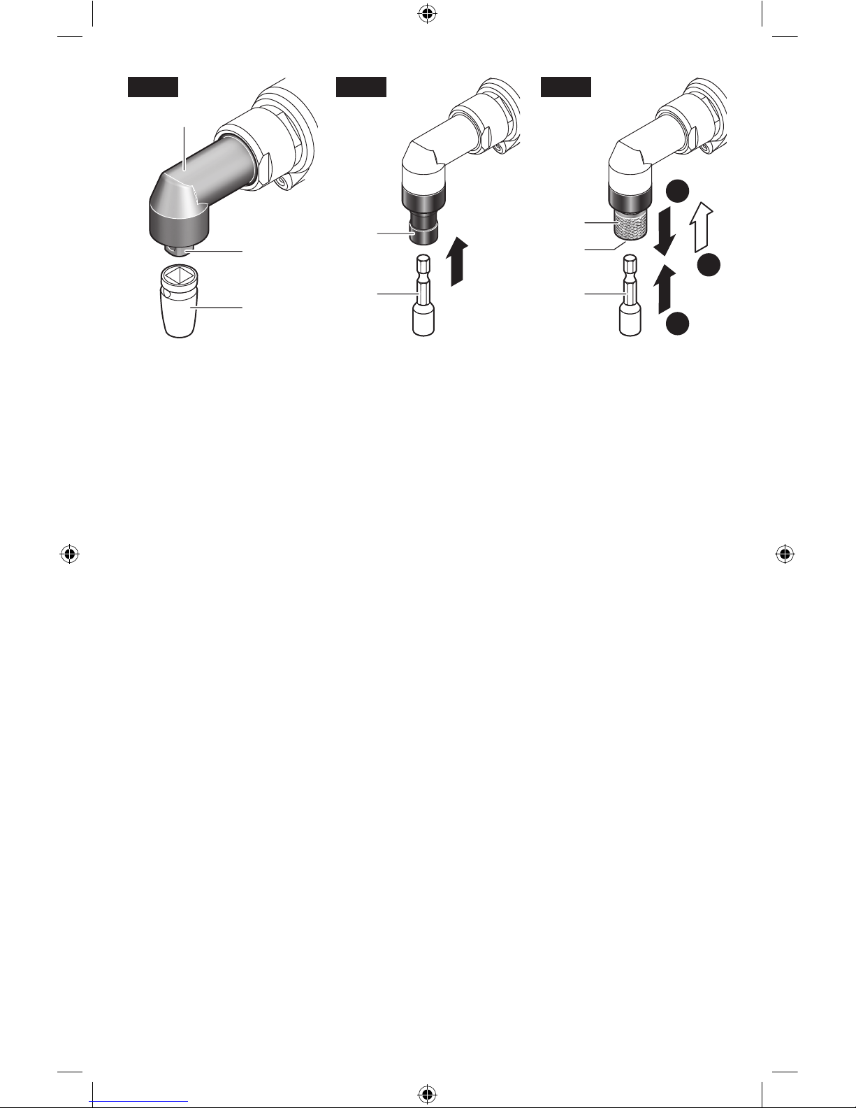
Fig. 8 Fig. 9 Fig. 10
CHANGING DRIVE
SOCKET ON THE
ANGLE HEAD WITH
EXTERNAL SQUARE
DRIVE
Inserting
– Press in the pin on the
square drive of the angle
head 2, e. g. using a small
screwdriver, and slide the
drive socket 1 over the
square drive. Pay attention
that the pin engages in the
recess of the tool bit (Fig.
8).
Removing
– Press in the pin on the
square drive through the
hole on the side of the
drive socket, then pull the
socket off the square drive
of the angle head 2 (Fig. 8).
CHANGING DRIVE
BIT ON THE ANGLE
HEAD WITH INTERNAL
HEXAGON
Inserting
– Insert the tool bit 1 into the
internal hex socket of the
tool holder 2 until it can be
felt to engage (Fig. 9).
Removing
– Pull the tool bit 1 off of the
tool holder 2 with the aid of
pliers, if necessary (Fig. 9).
CHANGING DRIVE BIT
ON THE ANGLE HEAD
WITH QUICK-CHANGE
CHUCK
Inserting
Use only insertion tools with
fitting end pieces (1/4” hexagonal) .
– Pull the sleeve of quick-
change chuck 24 to the
front and hold (Fig. 10).
– Insert tool bit 1 into tool
holder 2 and release the
quick-change chuck (Fig.
10).
Removing
– Pull the sleeve of quick-
change chuck 24 to the
front and hold (Fig. 10).
– Remove tool bit 1 from tool
holder 2 and release the
quick-change chuck (Fig.
10).
160992A3VR.indb 14 3/7/17 12:22 PM
15
Operating Instructions
Disconnect battery pack
from tool before making
any assembly, adjustments or changing
accessories. Such preventive safety mea-
sures reduce the risk of starting the tool accidentally.
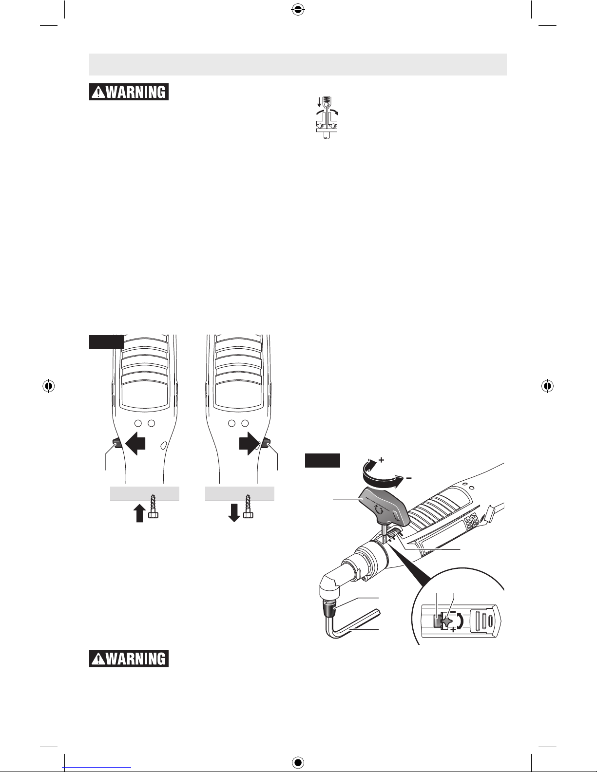
Starting operation
When starting the power tool, you should first
select the direction of rotation with the rotational direction switch 11 since the power tool
starts only when the rotational direction switch
11 is not in the middle position (switch-on lock)
(Fig. 1).
Reversing the rotational direction
– Right rotation: For driving in screws, push
the rotational direction switch 11 left to the
stop (Fig. 11).
– Left Rotation: For loosening or unscrewing
screws, push the rotational direction switch
11 right to the stop (Fig. 11).
Switching On the Worklight
The work area illumination 13 makes possible
the lighting of the screwing position for unfavorable light conditions. The work area illumination 13 is switched on by lightly pressing
the on/off switch 10. When the on/off switch
is firmly pressed, the power tool is switched
on and the work area illumination continues
to light.
Do not look directly into
the work area illumination – your sight can be temporarily degraded!
Switching On and Off
The screwdriver has a shut-off
clutch that can be set for a torque in
a given range. It responds when the
torque that is set is reached.
– To start the tool press the on/off switch 10 to
the stop (Fig. 1).
– The tool switches off automatically as soon
as the preset torque is reached.
When the on/off switch 10 is released prematurely, the preset torque is not reached.
To save energy, only switch the power tool on
when using it.
Working Advice
Apply the power tool to the screw/nut only
when it is switched off. Rotating tool inserts can slip off.
Setting the Torque
The tightening torque is dependent on the
spring pretension of the shut-off clutch. The
shut-off clutch responds in right as well as left
rotation when the torque setting is reached.
For setting the individual tightening torques,
use only the adjustment tool 25 provided.
– Push the torques setting cover 6 on the
power tool completely back.
Applies for the following types: ANGLE
EXACT ION 3-500, 8-1100, 15-500, 23-380,
30-290.
– Insert an Allen key 26 into tool bit 1 and turn
it slowly (Fig. 12).
– When a small indentation (adjusting dial 27)
is visible in the clutch, insert the adjustment
11 11
Fig. 11
6
25
1
26
27 25
Fig. 12
160992A3VR.indb 15 3/7/17 12:22 PM
16
tool 25 into the indentation and turn it (Fig.
12).
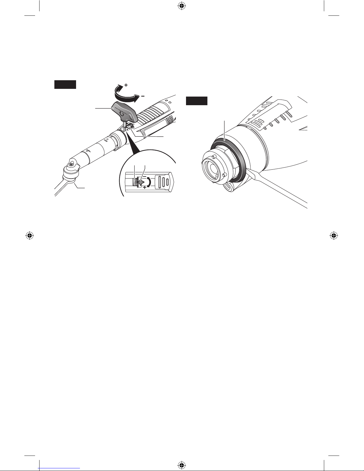
Applies for the following types: ANGLE EXACT ION 30-300, 40-220, 50-210, 60-120.
– Slowly turn the tool holder 2 using an open-
end spanner (Fig. 13).
– When a small indentation (adjusting dial 27)
is visible in the clutch, insert the adjustment
tool 25 into the indentation and turn it.
Turning in the clockwise direction results in a
higher torque, in the counterclockwise direction, a lower torque.
– Remove the adjustment tool 25. Shut the
torques setting cover 6 again to protect the
clutch against contamination.
Note: The required adjustment is dependent
on the type of threaded connection and can
be best determined by practical trials. Check
the trial fastenings with a torque wrench.
Set the torque only in the specified performance range, otherwise the shut-off clutch
will no longer respond.
Marking the Torque Setting
Always use the power tool with a marking ring
to insure that the housing body is sealed from
dust and dirt.
Applies for the following types: ANGLE EXACT ION 30-300, 40-220, 50-210, 60-120.
For these industrial cordless angle wrenches,
the angle head must be removed first, see “Adjusting and Removing the Angle head”, page
12.
The torque can be marked now as described
below.
Applies for the following types: ANGLE EXACT ION 3-500, 8-1100, 15-500.
To identify individually adjusted tightening
torques, the marking ring 17 can be replaced
with a marking ring of another color.
– Press off the marking ring 17 with a thin
screwdriver blade, a knife, or similar (Fig.
14).
Tightening Fastener Indicator
(green/red LED)
When the preset torque is reached, the shut
off coupling responds. The LED indicator 7
lights green (Fig. 1).
If the preset torque is not reached, the LED
indicator 7 lights red and an acoustical signal
sounds. The tightening fastener must be performed again.
Repeat Protection
When the shut-off coupling responds for a
tightened fastener, the motor shuts off. Switching on again is possible only after a 0.7 second delay. In this manner, an unintentional
re-tightening of an already seated screw is
avoided.
25
2
6
27 25
Fig. 13
17
Fig. 14
160992A3VR.indb 16 3/7/17 12:22 PM
 Loading...