


MODEL 250SXO - OUTDOOR MODEL
For exterior use only
Electronic Ignition and built in Freeze protection Suitable for heating potable water only Not approved for space heating purposes
250 SXO NG - Natural Gas
250 SXO LP - Liquefied Petroleum (LP) Gas
6 720 607 440 US (05.03) JS
Warning: If the information in this manual is not followed exactly, a fire or explosion may result causing property damage, personal injury or death. Do not store or use gasoline or other flammable vapor and liquids in the vicinity of this or any other appliance.
Improper installation, adjustment, alteration, service or maintenance can cause injury or property damage. Refer to this manual. For assistance or additional information consult a qualified installer, service agency or the gas supplier.
In the Commonwealth of Massachusetts this product must be installed by a licensed plumber or gas fitter.
Upon completion of the installation, these instructions should be handed to the user of the appliance for future reference.
What to do if you smell gas
•Close gas valve.
•Do not try to light any appliance.
•Do not touch any electrical switch; do not use any phone in your building.
•If you cannot reach your gas supplier, call the fire department.
•Immediately call your gas supplier from a neighbor’s phone. Follow the gas supplier’s instructions
•Installation and service must be performed by a qualified installer, service agency or the gas supplier.
Index
Index
1 |
Warning |
2 |
|
|
|
2 |
Appliance details |
4 |
2.1 |
Features |
4 |
2.2 |
250 SXO Specifications (Technical data) |
4 |
2.3 |
Dimensions and Minimum installation clearances |
6 |
2.4 |
General rules to follow for safe operation |
7 |
2.5 |
Proper location for installing your heater |
7 |
2.6 |
Heater Placement and Clearances |
8 |
2.7 |
Mounting installation |
8 |
2.8 |
Gas piping & connections |
10 |
2.9 |
Measuring gas pressure |
12 |
2.9.1 |
Connecting Manometer |
12 |
2.9.2 |
Static Pressure Test |
12 |
2.9.3 |
Operating Pressure Test |
12 |
2.10 |
Water connections |
13 |
2.11 |
Electrical connections |
14 |
2.12 |
Operating instructions |
14 |
2.13For your safety read before operating your water
|
heater |
15 |
2.14 |
Lighting and operating instructions |
15 |
|
|
|
3 |
Operation instructions |
16 |
3.1 |
Power |
16 |
3.2 |
Temperature selection |
16 |
3.3 |
Use of remote control accessory |
18 |
3.4 |
Operation |
18 |
3.5 |
Reset button |
18 |
3.6 |
Program button |
18 |
3.7 |
Locked condition |
18 |
|
|
|
4 |
Maintenance and service |
19 |
|
|
|
5 |
Troubleshooting |
19 |
|
|
|
6 |
Electrical diagram |
22 |
|
|
|
7 |
250 SXO Functional scheme |
23 |
|
|
|
8 |
Interior components diagram and parts list |
24 |
8.1 |
Interior components |
24 |
8.2 |
Components diagram |
25 |
8.3 |
Parts list |
26 |
9Special adjustment for measuring and adjusting
|
CO2 levels |
27 |
|
|
|
10 |
Protecting the environment |
29 |
|
|
|
11 |
Twelve Year Limited Warranty |
30 |
1Warning
Warning: If the information in this manual is not followed exactly, a fire or explosion may result causing property damage, personal injury or death.
Warning: Improper installation, adjustment, alteration, service or maintenance can cause injury or property damage. Refer to this manual. For assistance or additional information consult a qualified installer, service agency or the gas supplier.
Upon completion of the installation, these instructions should be handed to the user of the appliance for future reference.
Featuring
Electronic Ignition and Power Venting.
For your safety
Do not store or use gasoline or other flammable, combustible or corrosive vapors and liquids in the vicinity of this or any other appliance.
Warning: Carefully plan where you install the heater. If a gas appliance is not installed correctly, fatal accidents can result from lack of air, carbon monoxide poisoning or fire.
Warning: Place the heater in a location where water leaks will do NO DAMAGE to adjacent areas or floors.
Warning: Field wiring connections and electrical grounding must comply with local codes, or in the absence of local codes, with the latest edition of the National Electric Code, ANSI/NFPA 70, or in Canada, all electrical wiring must comply with the local codes and the Canadian Electrical Code, CSA C22.1 Part 1.
Warning: Shock hazard line voltage is present. Before servicing the water heater, turn off the electrical power to the water heater at the main disconnect or circuit breaker. Failure to do so could result in severe personal injury or death.
2 |
6 720 607 440 |

Warning
What to do if you smell gas
•Close gas valve.
•Do not try to light any appliance.
•Do not touch any electrical switch; do not use any phone in your building.
•Immediately call your gas supplier from a neighbor’s phone. Follow the gas supplier’s instructions.
•If you cannot reach your gas supplier, call the fire department.
•Installation and service must be performed by a qualified installer, service agency or the gas supplier.
Warning: The heater must be disconnected from the gas supply piping system during any pressure testing of that system at test pressures equal to or more than 0.5 psig.
FCC:
This device complies with Part 15 of the FCC rules. Operation is subject to the following two conditions: (1) This device may not cause harmful interference, and (2) this device must accept any interference received, including interference that may cause undesired operation.
Caution: Any changes or modifications not expressly approved by the party responsible for compliance could void the user’s authority to operate the equipment.
Fig. 1
Fig. 2
6 720 607 440 |
3 |

Appliance details
2Appliance details
2.1Features
Parts
•Touch Pad interface control
•High power pre-mix compact burner with low NOx emissions
•Modulating Gas Valve with constant gas: air ratio control
•Modulating water valve for improved comfort and temperature control
•Freeze protection.
Safety
•Flame sensor (ionization) rod
•Overheat sensor
•Temperature limiter
•Fan speed monitoring.
High Quality Materials for Long Working Life
•Copper heat exchanger
•High efficiency Ceramat Burner
•Compact space saver: mounts on a wall with a supplied bracket.
•Easily removable two-piece cover.
Features
•Electronic Ignition
•LCD Display
•On/Off and Temperature control switches
•Reset button
•Program Key (Selectable temperature default)
•Failure codes for easy diagnostic and repair. Accessories
•Optional wireless remote control accessory to operate with the appliance.
BOSCH is constantly improving its
iproducts, therefore specifications are subject to change without prior notice.
2.2250 SXO Specifications (Technical data)
Approved in US/Canada
Capacity
Maximum flow rate: 6.35 GPM (24 l/min) at a 45°F (25°C) rise.
Maximum output
142,968 Btu/h (41.8 kW)
Maximum input
175,000 Btu/h (51.2 kW)
Efficiency in %
Recovery efficiency 86.5%
Min. Output
31,131 Btu/h (9,1 kW)
Temperature Control
Selection range: 100°F (38°C) - 140°F (60°C) Default temperature: 122°F (50°C)
Stability: +/- 2°F (+/- 1°C)
Gas Requirement
Gas connection (inches) - ¾”
Inlet gas pressure under maximum operation*
•Propane: 11” - 14” water column
•Natural Gas: 5” - 14” water column.
* To measure Gas Pressure, see Measuring Gas Pressure, chapter 2.9.
Water
•Hot water connection (inches) - ¾”
•Cold water connection (inches) - ¾”
•Water valve material: Polymer (PPS) (Polypropylene Sulfid)
•Minimum water flow: 0.8 gallon/minute (3 l/m)
•Minimum recommended water pressure: 30 PSI (2.07 bar)
•Connections:
– Bottom of heater
4 |
6 720 607 440 |

Appliance details
Combustion
•NOx ≤ 55 ppm
•CO ≤ 250 ppm.
Dimensions
•Depth (in): 8 ½” (220 mm)
•Width (in): 15 ¾” (400 mm)
•Height (in): 26” (650 mm)
•Weight: 47 pounds (21 kg).
Gas types
Natural Gas. LP Gas.
CO2 analyzer is required to convert from one gas type to another. Please contact CEC for specific instructions.
Voltage
120 V AC (50/60 Hz)
Amperage
IDLE - 40 mA
Operation - ≤ 2,5 A
Noise
≤ 50 db (A)
Safety devices
•Flame failure device (ionization flame rod sensor)
•Pressure relief valve (supplied with heater)
•Over heat prevention (temperature limiter).
Water resistant
IP X5 (protection against water drops).
UNPACKING THE 250 SXO HEATER
This heater is packed securely.
The box includes:
•Control panel shield
•Pressure relief valve
•Bracket for wall hanging the heater
•Plastic decal shields for covering front cover screws and control panel, installer should affix these decals to the front of the unit after installation is complete. See Fig. 6
•Installation manual
•Product registration card.
Do not lose this manual. Please complete and return the enclosed product registration card.
Before installing the unit, be certain you have the correct heater for your type of Gas - Propane or Natural Gas. Identification labels are found on the shipping box, and on the rating plate which is located on the right side panel of the cover.
The 250SXO is not approved or designed for:
•Manufactured (mobile) homes, RV's or boats
•Heating or other recirculating/pumping applications*
•Solar/preheat backup or high temperature booster use
* This includes domestic hot water circulator pump loop systems that may previously exist in a home hot water system. The use of a small electric mini-tank (4-6 gallon size) should be used for this application; when designed so the pump will circulate the hot water in the mini-tank only and through the building's hot water return loop (timed or thermostatic controlled operation of the pump is commonly done). The 250SXO should be plumbed in line before the mini-tank water heater, contact CEC if further instruction is needed.
6 720 607 440 |
5 |
Appliance details
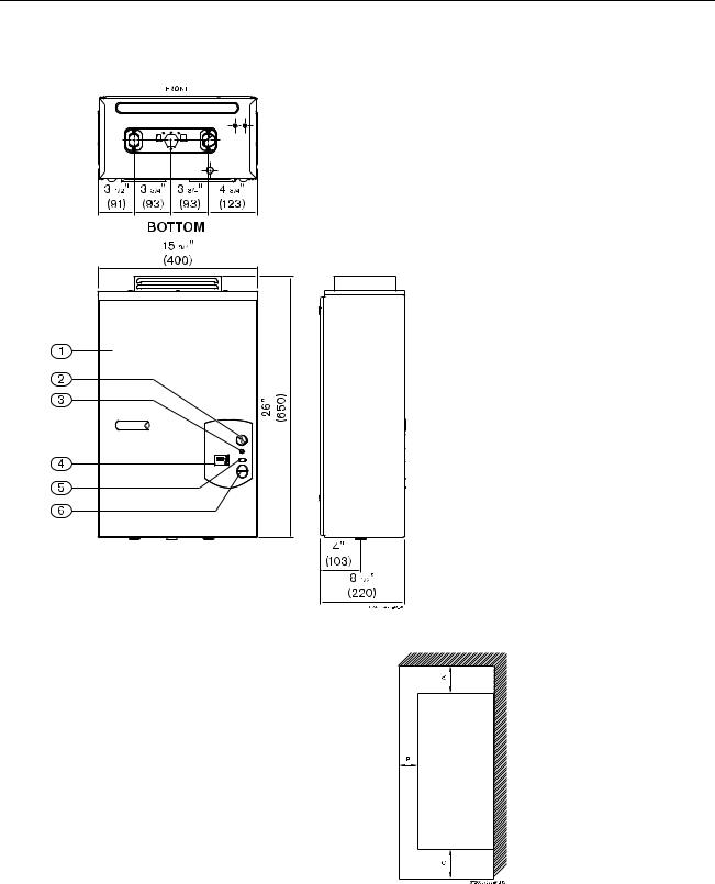
2.3Dimensions and Minimum installation clearances
Fig. 3 Dimensions
1Cover
2 On/Off switch
3 Reset button
4 LCD display
5 Program button
6 Temperature buttons
Fig. 4 Minimum clearances
|
Model 250 SXO |
|
TOP (A) |
3 |
ft. |
FRONT (B) |
4 |
ft. |
BACK |
0” |
|
SIDES |
4 |
ft. |
BOTTOM (C) |
1 |
ft. |
Table 1 Minimum clearances
6 |
6 720 607 440 |
Appliance details
2.4General rules to follow for safe operation
B1. You should follow these instructions when you install your heater. In the United States: The installation must conform with local codes or, in the absence of local codes, the National Fuel Gas Code ANSI Z223.1/NFPA 54.
In Canada: The Installation should conform with CGA B149.(1,2) INSTALLATION CODES and /or local installation codes.
B2. Carefully plan where you install the heater. Proper clearances must be followed.
B3. The appliance must be isolated from the gas supply piping system by closing its individual manual gas shutoff valve (not supplied with heater) during any pressure testing at pressures in excess of ½ Psig (3.5 kPa).
The appliance and its gas connection must be leak tested before placing the appliance in operation.
B4. Keep water heater area clear and free from combustibles and flammable liquids. Do not locate the heater over any material which might burn.
B5. Correct gas pressure is critical for the optimum operation of this heater. Gas piping must be sized to provide the required pressure at the maximum output of the heater, while all the other gas appliances are in operation. Check with your local gas supplier, and see the section on connecting the gas supply.
B6. Should overheating occur or the gas supply fail to shut off, turn off the gas supply at the manual gas shut off valve, on the gas line. Note: manual gas shutoff valve is not supplied with the heater.
B7. Do not use this appliance if any part has been underwater. Immediately call a qualified service technician to inspect the appliance and to replace any part of the control system and any gas control which has been underwater.
2.5Proper location for installing your heater
Carefully select the location of the water heater. Follow the guidelines below:
B 1. Locate the heater where venting, gas and plumbing connections are feasible and convenient.
B2. The hot water lines should be kept short to save energy. Centrally locating the water heater is best. It is always best to have the water lines insulated to prevent the possibility of any freeze damage.
B3. The water in this heater is cold and always remains cold except for the times that hot water is being used. The heater is equipped with freeze prevention equipment that will operate and prevent freezing of the water in the heater to 5°F with no wind chill. Electrical power must be maintained to the heater to allow this to function.
WARNING: Proper insulation of the water lines below the heater is required if below freezing temperatures, below 32°F, are ever anticipated!
Danger: If the temperature drops below 5°F, freeze damage to the water heater itself must be prevented by turning off the power to the heater, then disconnecting the plumbing connections and introducing short bursts of compressed air (20-40 psi) through the heater's connections. This will remove the residual water in the horizontal pipes and water valve..
Danger: Keep children away as the top of the water heater vent cap will get very hot during operation. Install in a place that prevents the top of the heater being reached by small children.
Danger: Flue gases will be released through the vent cap. Flue gas is very hot and contains carbon monoxide. The heater cannot be installed indoors. To prevent risk of fire and poisoning by carbon monoxide, assure all clearances indicated in manual.
Danger: Surface temperature around vent cap is less than 140°F, except highest top surface of vent cap may reach 400°F.
Danger: Do not place or store any combustible material within 5 feet of the appliance. Risk of fire could be caused by hot flue gas. Note: Exception is made for the wall where the appliance is installed and any adjacent walls or overhang. In this case observe clearances required in chapter 2.6.
Warning: Flammable materials, gasoline, pressurized containers, or any other items or articles that are potential fire hazards must NOT be placed on or adjacent to the heater. The appliance area must be kept free of all combustible materials, gasoline and other flammable vapors and liquids.
6 720 607 440 |
7 |

Appliance details
2.6Heater Placement and Clearances
The 250 SXO is design certified for installation directly on a combustible wall. (see 2.7 Mounting installation) For installation on vinyl siding see Fig. 10. Keep the area below the heater free of combustible material.
Minimum clearances
If the appliance is installed under an overhang, there must be a 36” clearance from the top of the appliance and the mounting area must be open in front and on the sides of the appliance.
2.7Mounting installation
Warning: before starting installation:
B check that there are no loose parts inside the appliance
Bensure that gas pipe, gas valve, mixer, fan and burner have no damage and are properly fitted.
Front cover should be removed in order to i inspect components visually (see
instructions below).
To remove front cover.
BLoosen the two Philips head screws located on front panel (beneath plastic decal shields if they are already attached, see Fig. 6).
Fig. 5
|
|
|
Danger: The top of the kit will get hot |
||
|
|
|
due to the flue gases. Install away from |
||
|
|
|
children. |
|
|
|
|
|
|
||
|
|
|
|
|
|
|
|
|
|
|
|
Ref. |
Description |
Min. |
|||
distances |
|||||
|
|
|
|
||
A |
Directly below or from an |
|
|||
|
|
|
opening; operable windows, |
³ 4 ft |
|
B |
|||||
doors and any fresh air |
|||||
|
|
|
|
||
C |
|
||||
openings |
|
||||
|
|
|
|
|
|
D |
From any adjacent wall or tall |
³ 4 ft |
|||
shruberry |
|||||
|
|
|
|
||
E |
Below a gutter, sanitary |
³ 3 ft |
|||
pipework, eaves or overhang |
|||||
|
|
|
|
||
|
|
|
|||
F |
Above ground |
³ 1 ft |
|||
|
|
|
|
|
|
G |
From a gas meter, gas |
³ 3 ft |
|||
regulator, electrical box or |
|||||
|
|
|
another 250SXO heater |
|
|
|
|
|
|
|
|
Table 2 Clearances
Plastic decals
Fig. 6 Remove front cover
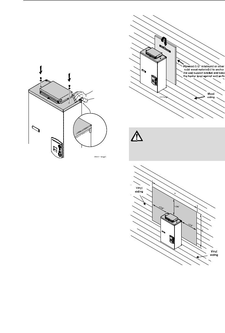
BRemove the two top screws securing the vent cap to the top of the heater, being careful the washers on the screws are not lost, see Fig. 7.
Fig. 7
B Lift the top vent cap completely upward from the heater.
BFrom the bottom of the heater, holding the sides, lift the front cover panel of the heater upward and slightly toward you to remove.
8 |
6 720 607 440 |
Appliance details
B After inspection, replace front cover and tighten screws, then replace plastic decal shields.
BFix the top vent cap on the top of the heater, as shown in Fig. 8). Make sure the vent cap is well fitted
by taking special care that the front cover stays inside the extended corners of the vent cap, as shown in Fig. 8). The sides of the cover must be pressed with your hands to ensure it fits inside those corners. Secure it in place with its two screws.
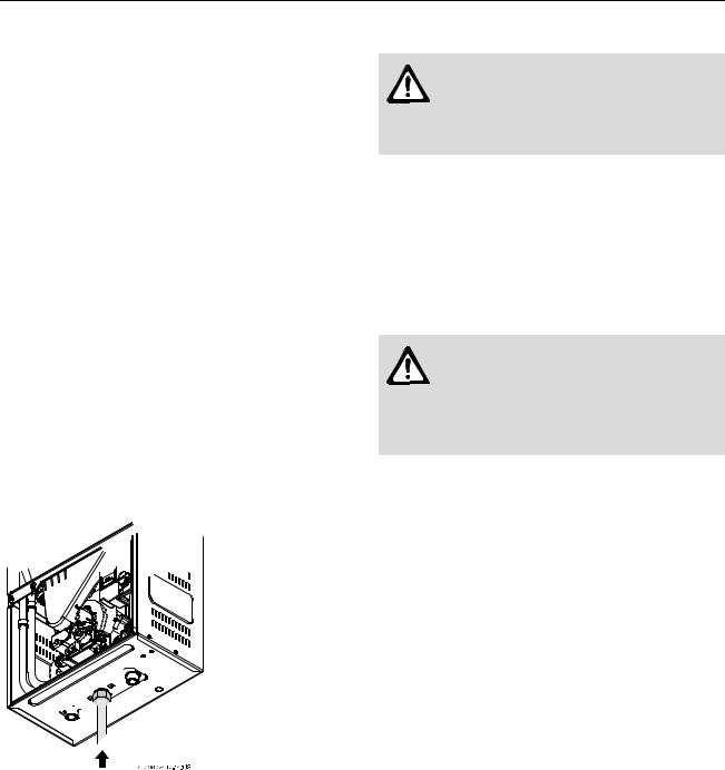
Fig. 9
Fig. 8
BThe water heater is design certified for mounting on a wall. Secure the wall mounting bracket provided with the water heater to a wall surface. See Fig. 9.
BThe installation method of the mounting bracket will
depend on what type of surface it’s being mounted to. Due to the varying types of building surfaces, the installer must decide on how best to support and level the heater on an outside wall. It is always recommended that horizontal or vertical support boards or plywood sheathing (1/2” minimum) first be attached to the wall surface. The heater must also be kept level on the wall surface.
Warning: Do not mount heater directly to vinyl siding. With vinyl siding surfacing, a 6' x 4' area of the siding must first be removed and then replaced with wood or other non-plastic made material. See Fig. 10.
Fig. 10
Vent Safety System
The 250 SXO will shut down if the intake or exhaust louvers on the vent cap are blocked for any reason; see troubleshooting section on page 19. See error code table to confirm error, correct the problem and then reset the heater before operating.
6 720 607 440 |
9 |
Appliance details
2.8Gas piping & connections 
Before connecting the gas supply, check the rating plate on the right side of the heater to be sure that the heater is rated for the same gas to which it will be connected.
In the United States: The installation must conform with local codes or, in the absence of local codes, the National Fuel Gas Code ANSI Z223.1/NFPA 54.
In Canada: The Installation should conform with CGA B149 INSTALLATION CODES and/or local installation codes.
GAS LINE SIZING
The gas supply piping should be sized according to the applicable plumbing code for a maximum draw of 175,000 BTUH. Measure the length of gas supply line and use the tables in Fig. 12 or the gas line manufactures sizing tables to determine the pipe diameter necessary to accommodate the BTU demand of the unit. If there are more gas drawing appliances on the line, size the gas line according to the total maximum amount of BTU draw for all appliances.
Note: Under sizing the gas line may result in diminished output and improper operation. See chapter 2.9 for the procedure to confirm gas pressure.


 Inlet gas particle screen Gas piping
Fig. 11
BInstall a manual gas shut off valve, on the gas supply line.
BThe use of a union when connecting gas pipe to the gas inlet connection is important, this will facilitate any necessary servicing and cleaning of the inlet gas particle screen.
BThe minimum diameter required for any appliance connector used is ¾”.
BNational Fuel Gas Code requires that a sediment trap (drip leg) be installed on gas appliances not so equipped. The drip leg must be accessible and not subject to freezing conditions. Install in accordance with the recommendations of the serving gas supplier.
Warning: The heater must be isolated from the gas supply piping system during any pressure testing of that system at test pressures equal to or more than 0.5 psig.
The water heater must not be piped with gas supply pressures in excess of 0.5 psig. If overpressure has occurred, such as through improper testing of the gas lines or malfunction of the supply system, the gas valve must be checked for safe operation.
When connections are made, check for gas leaks at all joints. Apply some gas leak detection solution to all gas fittings. Bubbles are a sign of a leak. A Combustible Gas Detector may also be used to detect for leaks.
Danger: If you have a leak, shut off the gas. Tighten appropriate fittings to stop leak. Turn the gas on and check again with a gas leak detection solution. Never test for gas leaks using a match or flame.
10 |
6 720 607 440 |
 Loading...