


IMPORTANT: |
IMPORTANT : |
IMPORTANTE: |
Read Before Using |
Lire avant usage |
Leer antes de usar |
Operating/Safety Instructions
Consignes de fonctionnement/sécurité
Instrucciones de funcionamiento y seguridad
1594
Consumer Information
Renseignement des consommateurs
Información para el consumidor
Toll Free Number: |
Appel gratuit : |
Número de teléfono gratuito: |
1-877-BOSCH99 (1-877-267-2499) http://www.boschtools.com |
||
|
|
|
For English |
Parlez-vous français? |
¿Habla español? |
See page 2 |
Voir page 15 |
Ver página 28 |

|
Power Tool Safety Rules |
|
|
Read and understand all instructions. Failure to follow all instructions listed |
|
! WARNING |
||
below, may result in electric shock, fire and/or serious personal injury. |
||
|
||
|
SAVE THESE INSTRUCTIONS |
Work Area
Keep your work area clean and well lit.
Cluttered benches and dark areas invite accidents.
Do not operate power tools in explosive atmospheres, such as in the presence of flammable liquids, gases, or dust. Power tools create sparks which may ignite the dust or fumes.
Keep by-standers, children, and visitors away while operating a power tool.
Distractions can cause you to lose control.
Electrical Safety
Double Insulated tools are equipped with a polarized plug (one blade is wider than the other.) This plug will fit in a polarized outlet only one way. If the plug does not fit fully in the outlet, reverse the plug. If it still does not fit, contact a qualified electrician to install a polarized outlet. Do not change the plug in any way. Double Insulation 


 eliminates the need for the three wire grounded power cord and grounded power supply system. Before plugging in the tool, be certain the outlet voltage supplied is within the voltage marked on the nameplate. Do not use “AC only” rated tools with a DC power supply.
Avoid body contact with grounded surfaces such as pipes, radiators, ranges and refrigerators. There is an increased risk of electric shock if your body is grounded. If operating the power tool in damp locations is unavoidable, a Ground Fault Circuit Interrupter must be used to supply the power to your tool. Electrician’s rubber gloves and footwear will further enhance your personal safety.
Don't expose power tools to rain or wet conditions. Water entering a power tool will increase the risk of electric shock.
Do not abuse the cord. Never use the cord to carry the tools or pull the plug from an outlet. Keep cord away from heat, oil, sharp edges or moving parts. Replace damaged cords immediately. Damaged cords increase the risk of electric shock.
When operating a power tool outside, use an outdoor extension cord marked "W-A" or "W." These cords are rated for outdoor use and reduce the risk of electric shock. Refer to “Recommended sizes of Extension Cords” in the Accessory section of this manual.
Personal Safety
Stay alert, watch what you are doing and use common sense when operating a power tool. Do not use tool while tired or under the influence of drugs, alcohol, or medication. A moment of inattention while operating power tools may result in serious personal injury.
Dress properly. Do not wear loose clothing or jewelry. Contain long hair. Keep your hair, clothing, and gloves away from moving parts. Loose clothes, jewelry, or long hair can be caught in moving parts. Keep handles dry, clean and free from oil and grease.
Avoid accidental starting. Be sure switch is “OFF” before plugging in. Carrying tools with your finger on the switch or plugging in tools that have the switch “ON” invites accidents.
Remove adjusting keys or wrenches before turning the tool “ON”. A wrench or a key that is left attached to a rotating part of the tool may result in personal injury.
Do not overreach. Keep proper footing and balance at all times. Proper footing and balance enables better control of the tool in unexpected situations.
Use safety equipment. Always wear eye protection. Dust mask, non-skid safety shoes, hard hat, or hearing protection must be used for appropriate conditions.
Tool Use and Care
Use clamps or other practical way to secure and support the workpiece to a stable platform. Holding the work by hand or against your body is unstable and may lead to loss of control.
-2-

Do not force tool. Use the correct tool for your application. The correct tool will do the job better and safer at the rate for which it is designed.
Do not use tool if switch does not turn it “ON” or “OFF”. Any tool that cannot be controlled with the switch is dangerous and must be repaired.
Disconnect the plug from the power source before making any adjustments, changing accessories, or storing the tool. Such preventive safety measures reduce the risk of starting the tool accidentally.
Store idle tools out of reach of children and other untrained persons. Tools are dangerous in the hands of untrained users.
Maintain tools with care. Keep cutting tools sharp and clean. Properly maintained tools, with sharp cutting edges are less likely to bind and are easier to control. Any alteration or modification is a misuse and may result in a dangerous condition.
Check for misalignment or binding of moving parts, breakage of parts, and any other condition that may affect the tools
operation. If damaged, have the tool serviced before using. Many accidents are caused by poorly maintained tools. Develop a periodic maintenance schedule for your tool.
Use only accessories that are recommended by the manufacturer for your model. Accessories that may be suitable for one tool, may become hazardous when used on another tool.
Service
Tool service must be performed only by qualified repair personnel. Service or maintenance performed by unqualified personnel could result in a risk of injury. For example: internal wires may be misplaced or pinched, safety guard return springs may be improperly mounted.
When servicing a tool, use only identical replacement parts. Follow instructions in the Maintenance section of this manual.
Use of unauthorized parts or failure to follow Maintenance Instructions may create a risk of electric shock or injury. Certain cleaning agents such as gasoline, carbon tetrachloride, ammonia, etc. may damage plastic parts.
Safety Rules for Planers
Secure the material being planed. Never hold it in your hand or across legs. Small workpiece must be adequately secured so that the rotating planer blades will not pick it up during forward motion of the planer. Unstable support can cause the blades to bind causing loss of control and injury.
Make sure the spring operated automatic retracting rabbet guard returns to blade covering position instantly. The blades are hidden from view and you may be cut if blade is contacted.
Always start the plane before blade is in contact with the workpiece and allow the blade to come to full speed. Tool can vibrate or chatter if blade speed is too slow at beginning of cut and possibly kickback.
Check the workpiece for nails, if there are nails, either remove or set them well below intended finished surface. If the planer blades strike objects like nails it may cause the tool to kickback and serious personal injury may result.
Never leave the trigger locked “ON”. Unplug the planer before changing accessories. Before plugging the tool in, check that the trigger lock is "OFF".
Accidental start-ups may occur if planer is plugged in while changing an accessory.
After changing blades, rotate the blade drum to make sure blades are not hitting any part of the blade head housing and the blade locking screws are tight.
Spinning blades could strike tool housing and damage tool as well as possible injury.
-3-

Always hold the tool firmly with both hands for maximum control.
Never pull the plane backward over the workpiece. Loss of control may occur.
Do not put fingers or any objects into the chip ejector or clean out chips while tool is running. Contact with blade drum will cause injury.
Remove plug from power source if it becomes necessary to remove chips. The blades are hidden from view and you may be cut if blade is contacted.
Never place the plane down until the blade is completely at rest. Surface contact with coasting blade drum may cause the plane to walk out of control.
Never use dull or damaged blades. Sharp blades must be handled with care.
Damaged blades can snap during use. Dull blades require more force to push the tool, possibly causing the blade to break.
Some dust created by power sanding, sawing, grinding, drilling, and other construction
activities contains chemicals known to cause cancer, birth defects or other reproductive harm. Some examples of these chemicals are:
•Lead from lead-based paints,
•Crystalline silica from bricks and cement and other masonry products, and
•Arsenic and chromium from chemicallytreated lumber.
Your risk from these exposures varies, depending on how often you do this type of work. To reduce your exposure to these chemicals: work in a well ventilated area, and work with approved safety equipment, such as those dust masks that are specially designed to filter out microscopic particles.
-4-

Symbols
IMPORTANT: Some of the following symbols may be used on your tool. Please study them and learn their meaning. Proper interpretation of these symbols will allow you to operate the tool better and safer.
Symbol |
Name |
Designation/Explanation |
||||||||
|
|
|
|
|
|
|
|
|
|
|
|
|
|
|
V |
Volts |
Voltage (potential) |
||||
|
|
|
|
A |
Amperes |
Current |
||||
|
|
|
|
|
|
|
|
|
|
|
|
|
Hz |
Hertz |
Frequency (cycles per second) |
||||||
|
|
|
W |
Watt |
Power |
|||||
|
|
kg |
Kilograms |
Weight |
||||||
|
|
|
|
|
|
|
|
|
|
|
|
min |
Minutes |
Time |
|||||||
|
|
|
|
s |
Seconds |
Time |
||||
|
|
|
|
|
|
|
|
|
|
|
|
|
|
|
|
|
|
|
|
Diameter |
Size of drill bits, grinding wheels, etc. |
|
|
|
|
|
|
|
|
|
|
|
|
|
|
n0 |
No load speed |
Rotational speed, at no load |
|||||
.../min |
Revolutions or reciprocation per minute |
Revolutions, strokes, surface speed, |
||||||||
|
|
|
|
|
|
|
|
|
|
orbits etc. per minute |
0 |
|
|
|
Off position |
Zero speed, zero torque... |
|||||
|
|
|
|
|
|
|
|
|
|
|
1, 2, 3, ... |
Selector settings |
Speed, torque or position settings. |
||||||||
I, II, III, |
|
Higher number means greater speed |
||||||||
|
|
|
|
|
|
|
|
|
|
|
0 |
|
|
|
|
|
|
Infinitely variable selector with off |
Speed is increasing from 0 setting |
||
|
|
|
|
|
|
|
|
|
Arrow |
Action in the direction of arrow |
|
|
|
|
|
|
|
|
|
||
|
|
|
|
|
|
|
|
|
Alternating current |
Type or a characteristic of current |
|
|
|
|
|
|
|
|
|
|
|
|
|
|
|
|
|
|
|
|
Direct current |
Type or a characteristic of current |
|
|
|
|
|
|
|
|
|
||
|
|
|
|
|
|
|
|
|
Alternating or direct current |
Type or a characteristic of current |
|
|
|
|
|
|
|
|
|
||
|
|
|
|
|
|
|
|
|
|
|
|
|
|
|
|
|
|
|
|
Class II construction |
Designates Double Insulated |
|
|
|
|
|
|
|
|
|
||
|
|
|
|
|
|
|
|
|
|
Construction tools. |
|
|
|
|
|
|
|
|
|
|
|
|
|
|
|
|
|
|
|
|
|
|
|
|
|
|
|
|
|
|
|
Earthing terminal |
Grounding terminal |
|
|
|
|
|
|
|
|
|
||
|
|
|
|
|
|
|
|
|
Warning symbol |
Alerts user to warning messages |
|
|
|
|
|
|
|
|
|
||
|
|
|
|
|
|
|
|
|
||
|
|
|
|
|
|
|
|
|
Ni-Cad RBRC seal |
Designates Ni-Cad battery recycling |
|
|
|
|
|
|
|
|
|
|
program |
|
|
|
|
|
|
|
|
|
|
|
This symbol designates that this tool is listed by Underwriters Laboratories.
This symbol designates that this tool is listed by the Canadian Standards Association.
This symbol designates that this tool is listed to Canadian Standards by Underwriters Laboratories.
This symbol designates that this tool is listed by Underwriters Laboratories, and listed to Canadian Standards by Underwriters Laboratories.
This symbol designates that
this tool complies to NOM Mexican Standards.
-5-

Functional Description and Specifications
Disconnect the plug from the power source before making any assembly, adjustments or changing accessories. Such preventive safety
measures reduce the risk of starting the tool accidentally.
Planer
FIG. 1
“LOCK-OFF” RELEASE
BUTTON
DEPTH CHIP
ADJUSTMENT EXHAUST
KNOB PORT
WING |
TRIGGER |
KNOB |
SWITCH |
RABBETING DEPTH STOP (OPTIONAL)
FRONT SHOE 
CHAMFER
V-GROOVES
DRIVE BELT
COVER
SCREW |
CHIP EXHAUST PORT |
PORT SELECTOR LEVER
DELUXE BEVEL
GUIDE FENCE
GUIDE
BRACKET
|
PIVOT |
|
DEPTH |
FENCE |
|
|
|
|
SCALE |
|
WIDTH |
|
ROUND |
|
|
SCALE |
|
|
KNOB |
WING KNOB |
|
|
|
|
Note: Each unlabeled mark |
|
|
represents 0.5 mm. |
|
Model number |
1594 |
Maximum Capacities |
|
|
Voltage rating |
120 V 50 - 60Hz |
Planing depth |
0 |
- 3/32" (0 - 2.6mm) |
Amperage rating |
6.5 A |
Rabbeting depth |
0 |
- 5/16" (0 - 9mm) |
No load speed |
n0 16,500/min |
Planing width |
3-1/4" (82mm) |
|
-6-
Assembly
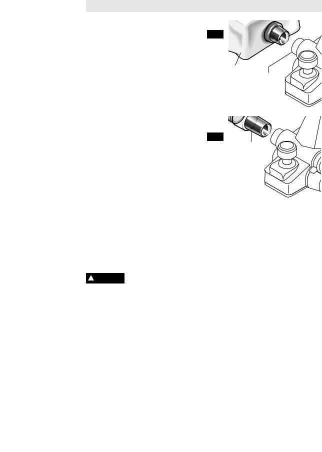
CHIP EXTRACTION
The planer comes with two chip exhaust ports, which may be used with a chip bag (Fig.2) or a shop vacuum and vacuum connector (Fig.3) to keep your work environment cleaner. The chip bag or vacuum connector may be attached to either end of the exhaust port.
Moving the port selector lever to position 1 (towards front of tool) discharges chips to the left, while position 2 (towards rear of tool) discharges chips to the right. (Fig. 1)
Included is the VAC002 adapter that will connect the hood to 1-1/4” and 1-1/2” vacuum hoses. An adapter to connect the hood to 2-1/2" hoses is also available separately.
PLANER BLADES
•There are three types of blades that can be used with the Bosch 1594 planer; standard mini tungsten carbide blades, Bosch Woodrazor micrograin mini tungsten carbide blades (standard equipment with the Bosch 1594 planer), and large HSS blades.
•While the Bosch 1594 mini tungsten carbide blades are sharper and more durable than standard mini tungsten carbide blades, the assembly and adjustment of both of Woodrazor and standard tungsten carbide blades are the same. Henceforth, all references in this manual to “mini TC blades” refer to both Woodrazor blades and standard mini tungsten carbide blades.
•To use large HSS blades with the 1594 it is necessary to purchase optional accessories.
Wear protective gloves ! WARNING when changing planer
blades. Edges are sharp and may cause injury.
REMOVING MINI TUNGSTEN
CARBIDE BLADES
Mini TC planer blades have two cutting edges, and may be reversed when one of the cutting edges becomes dull or chipped. (Fig. 6)
Before any work on the machine itself, pull the power plug.
FIG. 2
CHIP BAG
EXHAUST
PORTS
FIG. 3
VACUUM
CONNECTOR (OPTIONAL)
Always changes both blades at the same time. Otherwise, imbalance can cause vibration and reduce the useful service life of the tool. Use only blades designated for use with this model, because other blades can cause vibration, decrease performance and may not clamp securely in blade holder. Do not attempt to sharpen or use re-sharpened any TC blades.
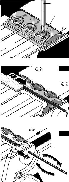
To remove the blades:
1.Rotate the blade drum until the clamping jaw is parallel to the planer shoe.
2.Loosen the three clamp screws by about one revolution each. (It is not necessary to remove the clamping jaw.) (Fig.4)
3.Slightly rotate the blade drum and use a piece of wood to push the blade sideways and out from under the clamping jaw. Make sure to keep your fingers away from the sharp edges of the blade. If the blade is gummed and difficult to remove, you may clean the blade and clamp with mineral spirits, lacquer thinner or alcohol. (Fig. 5)
-7-
4. Rotate the blade drum 180° and repeat |
FIG. 4 |
|
the procedure to remove the second |
|
|
blade. |
|
|
INSTALLING AND ADJUSTING MINI |
|
|
CARBIDE BLADES |
|
|
If the blades and/or holder are gummed and |
|
|
difficult to remove, remove the clamping |
|
|
jaws and screws and clean all surfaces with |
|
|
mineral spirits; lacquer thinner or alcohol, as |
|
|
this will ensure an accurate blade setting |
|
|
and proper tool performance. (See |
FRONT |
|
REMOVAL OF MINI TC BLADE HOLDERS |
||
SHOE |
||
AND RETAINERS) |
|
To install, carefully slide the blades onto ridges on the blade holders.
To ensure proper operation and an even cut, the blades must be positioned so that they are:
• Centered relative to the front and rear shoes.
• Aligned with each other.
• Positioned so that they will not touch against any part of the planer when rotated.
•Evenly pressed back toward the holder to ensure that they are level.
INSTALLATION PROCEDURE
1. Align the groove on top of the blade with the ridge of the blade holder and carefully slide the blade onto the blade holder, as shown in Figure 6.
2. Using a block of wood push the TC blade back towards the blade holder so that the inner side of the blade is pressed against the sloping part of the blade holder. (This will ensure that the blades are level.)
3.Then tighten the Torx clamping screws using the correct tightening sequence
(1,2,3), as shown in Figure 4, and your planer is ready for use.
Blade Retainer Screws - Under normal circumstances, the position of the retainer on the mini TC blade holders does not require readjustment. If fact, the screws that attach the retainer to the blade holder are factory sealed with a yellow fastening compound that should not be disturbed. However, if you believe that adjustments must be made, proper adjustment is critical, and it is best performed by a Bosch Factory Service or Bosch Authorized Service Center.
BLADE WRENCH
CLAMPING
JAW CLAMPING SCREW
BLADE
DRUM
BLADE
HOLDER
RIDGE
FIG. 5
FIG. 6
BLADE
HOLDER
-8-

CONVERSION TO HIGH-SPEED
STEEL BLADES
The 1594 Planer can be converted to accept large HSS blades. The conversion requires the optional PA1204 HSS Blades with Retainers (pair). (Fig. 7)
Additional pairs of HSS blade, the PA1205 large HSS blades, can also be purchased separately.
REMOVAL OF MINI TC BLADE
HOLDERS AND RETAINERS
1.Rotate the blade drum until the clamping jaw is parallel to the planer shoe.
2.Loosen the three clamp screws completely and remove the screws and clamping jaw.
3.Slightly rotate the blade drum and use a piece of wood to push the blade, holder and retainer off of the blade drum. Make sure to keep your fingers away from the sharp edges of the blade. If the blade is gummed and difficult to remove, you may clean the blade and clamp with mineral spirits, lacquer thinner or alcohol.
4.Rotate the blade drum 180° and repeat the procedure to remove the second blade.
INSTALLATION OF HSS BLADES
AND RETAINERS
Before inserting a new or sharpened blade, clean all surfaces (blades, retainer and drum) with mineral spirits; lacquer thinner or alcohol, as this will ensure an accurate blade setting and proper tool performance.
New or re-sharpened plane blades must be properly leveled before installation using the optional PA1206 HSS Blade Leveling Fixture. (The PA1204 HSS Blades with Retainers are leveled at the factory.)
To ensure proper operation and an even cut, the blades must be positioned so that they are:
•Centered relative to the front and rear shoes.
•Aligned with each other.
•Positioned so that they will not touch against any part of the planer when rotated.
Procedure:
1.To install the blades, carefully slide the blade/retainer assembly sideways to over one of the two clamping areas on the blade drum. The retainer must engage in the groove. (Fig. 8)
FIG. 7
BLADE
RETAINER
HSS
BLADE
GROOVE |
FIG. 8 |
2.Place a properly-oriented clamping jaw over the blade. (Fig. 4)
3.Tighten the three clamp screws with the Torx key using the correct tightening sequence (1,2,3). (Fig. 4)
4.Rotate the blade drum 180° and repeat the procedure for the second blade clamp.
REMOVING LARGE HSS BLADES
To remove the blades:
1.Rotate the blade drum until the clamping jaw is parallel to the planer shoe.
2.Loosen and remove the three clamp screws with the Torx key.
3.Also remove the clamping jaw.
4.Slightly rotate the blade drum and use a piece of wood to push the blade and retainer sideways and out of the blade drum. Make sure to keep your fingers away from the sharp edges of the blade. If the blade is gummed and difficult to remove, you may clean the blade and clamp with mineral spirits, lacquer thinner or alcohol.
Rotate the blade drum 180° and repeat the procedure to remove the second blade.
-9-

RESHARPENING HSS BLADES
Worn or dull HSS plane blades can be resharpened. The optimal blade angle of 50º should be maintained when sharpening.
Once a total of 6 mm of steel has been removed from tips of the blades, both blades must be replaced because the minimum HSS blade height is 23 mm from back to tip.
LEVELING OF HSS BLADES
A PA1206 HSS Blade Leveling Fixture (optional accessory) is required to level new or resharpened HSS blades. (Not necessary with the PA1204 HSS Blades and Retainers, which are leveled at the factory.)
1.Place the blade and blade retainer on the leveling fixture and make sure that the blade retainer engages in the grooves intended for this purpose. (Fig. 9)
2.Press the plane blade against the stop in front of the cutting edge to achieve the proper depth and evenness (levelness) and with the blade retainer in this position and tighten it with the locking screws. This will automatically adjust the blade to the correct height and levelness.
3.Tighten the retainer screws.
4.Remove blade and retainer assembly from the leveling fixture.
5.Repeat the procedure for the second blade.
BLADE
LEVELING
FIXTURE
BLADE
RETAINER
FIG. 9
HSS
BLADE
-10-
Operating Instructions
TRIGGER "ON/OFF" SWITCH
Hold the tool with both ! WARNING hands while starting the
tool, since torque from the motor can cause the tool to twist.
To turn tool "ON": depress the “Lock-Off” release button from either side and squeeze the trigger switch.
To turn the tool "OFF": release the trigger switch and it will return to "OFF" position automatically.
To increase switch life, do not turn switch on and off while tool and drum are held against a workpiece.
PLANING ACTION
Proper planing action helps to achieve the desired result. With practice and experience, it will become second nature. Make sure that the workpiece is held in place securely on your work surface, and standing comfortably, hold the planer firmly with both hands.
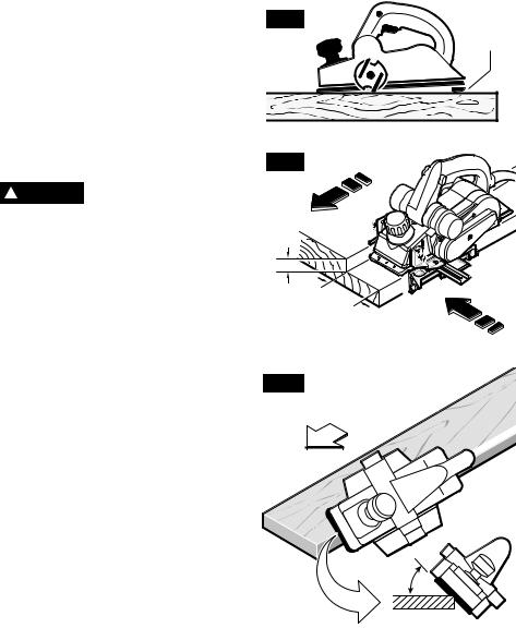
1.With the planer fully adjusted, place the front shoe on the workpiece, (be certain that the blade drum is not in contact with the work) and start the planer as described earlier.
2.With pressure on the front shoe, and the fence against the side of the work (to control the width or angle,) feed the planer
FIG. 10
PARK
REST
SHOE
steadily until the full length of the rear shoe passes over the edge of the workpiece. (Fig. 10)
3.Then gradually transfer pressure to the rear shoe, and continue planing to the end of the cut.
4.Feed the planer at a uniform and reasonable rate that does not put excessive strain on the motor or blades, (do not pull the planer back over the surface already cut.)
5.Use progressive cuts until you are near the desired depth, and then re-adjust to a shallow cut for the final pass to obtain a good surface finish.
The motor may stall if ! CAUTION improperly used or
overloaded. Reduce the pressure (feed rate) or depth of cut to prevent possible damage to the tool if the motor labors.
DEPTH OF CUT & FEED RATE
The cutting depth (planing depth) is determined by the difference in height between the adjustable front shoe and the fixed rear shoe of the planer. The depth knob adjusts the front shoe, which retracts and exposes the blade and determines the amount of material removed from the workpiece. The cutting depth range is from 0 to 3/32” or 2.6 mm per pass. (Fig. 1)
The appropriate depth of cut and feed rate depends on the workpiece material:
To avoid clogging and/or damage to the motor, a more shallow (thin) cut and/or a slower feed rate may be needed if the material has any of these characteristics: hardness; gumminess, sappiness, moisture, paint, varnish and/or knots. Also, when planing against the grain or across the grain
rather than with the grain, a shallower cut and/or slower feed rate is required. Whenever possible, test by planing a similar piece of scrap material.
Use multiple, progressive cuts to achieve the total desired depth.
Start with a shallow cut. If the plane moves freely through the workpiece with no excessive load on the motor, the depth setting can be increased before the next cut. (Do not change depth of cut while planing.)
When near the desired total depth, re-adjust the planing depth to a shallow setting for the final cut to obtain a good surface finish.
Adjusting the Depth of Cut: Rotate depth adjustment knob clockwise until the indicator is aligned with the desired cutting depth on the depth scale (Fig. 1).
-11-
PARK REST STAND
The park rest stand automatically springs down to help keep the blade from coming in contact with the work surface when planer is not in use (Fig. 11). The park rest stand is designed to swing up and out of the way by it itself when the back of the plane crosses the leading edge of the workpiece (Fig. 10). It will also swing up when planing begins in the middle of the work piece (in from the edge of the work piece).
UNCLOGGING THE CHIP EXHAUST
SYSTEM
Remove plug from power ! WARNING source if it becomes
necessary to manually remove chips. The blades are hidden from view and you may be cut if contacted.
To minimize the possibility of clogging, make sure:
1.Chip eject lever is all the way forward (left eject) or back (right eject).
2.The depth of cut is reasonable for the material.
3.The feed rate is reasonable for the material.
(See FEED RATE & DEPTH OF CUT)
If clogging occurs, stop the planer and move the chip eject lever back and forth. If this does not break up the clog, unplug the planer and carefully insert a screwdriver or similar object into the dust port to break up the clog.
DELUXE BEVEL GUIDE FENCE
The Deluxe Bevel Guide Fence (Fig. 12) can be used to cut various desired widths, with the additional capability of guiding the planer on any angle up to 45 degrees, to allow edge chamfering (Fig. 13).
Installing the angle fence: Place the wing knob through the appropriate hole in the guide bracket and screw into the housing. Securely tighten wing knob (Fig. 1).
Setting the cutting width: Loosen wing knob and using the width scale, slide the fence along the guide bracket to the desired position. Securely tighten wing knob (Fig. 1).
Setting the cutting angle: Loosen round knobs and pivot the fence to the desired position. Securely tighten round knobs (Fig. 1).
FIG. 11
PARK
REST
FIG. 12
9 mm max
82 |
mm |
|
|
max |
|
FIG. 13
45° |
Note that the adjustable front shoe contains three chamfer V-grooves, which will follow the corner of a workpiece to allow easier handling when using the deluxe angle/width fence (Fig. 13).
-12-
STRAIGHT GUIDE FENCE
The optional Straight Guide Fence can be used to cut various desired widths. (Fig. 14)
Installing the guide fence: Place the wing knob through the appropriate hole in the guide bracket and screw into the housing. Securely tighten wing knob.
Setting the cutting width: Loosen wing knob and slide the fence along the guide bracket to the desired position. Securely tighten wing knob. Be certain that the flat washer (supplied) is fitted between the bottom of the guide fence and wing knob or the guide fence is likely to slip.
RABBETING DEPTH STOP
The optional rabbeting depth stop accessory (Fig. 1) allows the user to set any rabbeting depth from 0 to 5/16 inch. For best results, it is important that the blade be properly aligned (See "BLADE ALIGNMENT"). The width of the rabbet is controlled by the width fence. The final depth is achieved by repetitive cutting until the rabbeting depth guide contacts the workpiece. The maximum rabbeting depth is 5/16"
Setting the rabbet depth: Loosen wing knob and using the depth scale on the rabbeting depth stop, set the desired rabbet depth. Securely tighten wing knob.
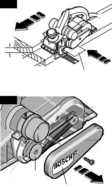
DRIVE BELT
The drive belt is a normal maintenance part and should be inspected periodically for wear. If the drive belt shows signs of drying out, cracking or tearing, it should be replaced. If the drive belt will not track properly or comes off the pulleys, it should be replaced.
Installing new drive belt: Loosen screw and remove the drive belt cover. Cut and remove the worn drive belt. Before installing the new drive belt, clean both pulleys thoroughly. First place the new drive belt onto the drive pulley then rotate clockwise while pushing the belt onto the driven pulley. Reinstall the drive belt cover and securely tighten screw (Fig. 15).
FIG. 14
9 mm max
|
82 |
mm |
|
|
|
|
max |
|
|
|
OPTIONAL STRAIGHT |
|
|
GUIDE FENCE |
FIG. 15 |
|
DRIVEN |
|
|
PULLEY |
SCREW
|
DRIVE |
|
|
PULLEY |
|
DRIVE |
DRIVE |
|
BELT |
||
BELT |
||
|
COVER |
-13-

Maintenance
Service
Preventive maintenance performed by unauthorized personnel may result in misplacing of
internal wires and components which could cause serious hazard. We recommend that all tool service be performed by a Bosch Factory Service Center or Authorized Bosch Service Station.
TOOL LUBRICATION
Your Bosch tool has been properly lubricated and is ready to use. It is recommended that tools with gears be regreased with a special gear lubricant at every brush change.
CARBON BRUSHES
The brushes and commutator in your tool have been engineered for many hours of dependable service. To maintain peak efficiency of the motor, we recommend every two to six months the brushes be examined. Only genuine Bosch replacement brushes specially designed for your tool should be used.
BEARINGS
After about 300-400 hours of operation, or at every second brush change, the bearings should be replaced at Bosch Factory Service
Center or Authorized Bosch Service Station. Bearings which become noisy (due to heavy load or very abrasive material cutting) should be replaced at once to avoid overheating or motor failure.
Cleaning
To avoid accidents always disconnect the tool from the power supply before cleaning or
performing any maintenance. The tool may be cleaned most effectively with compressed dry air. Always wear safety goggles when cleaning tools with compressed air.
Ventilation openings and switch levers must be kept clean and free of foreign matter. Do not attempt to clean by inserting pointed objects through openings.
Certain cleaning agents and solvents damage plastic parts. Some of these are: gasoline,
carbon tetrachloride, chlorinated cleaning solvents, ammonia and household detergents that contain ammonia.
Clean the park rest shoe regularly and ensure that it springs back freely.
Accessories
If an extension cord is necessary, a cord with adequate size conductors that is capable
of carrying the current necessary for your tool must be used. This will prevent excessive voltage drop, loss of power or overheating. Grounded tools must use 3-wire extension cords that have 3-prong plugs and receptacles.
NOTE: The smaller the gauge number, the heavier the cord.
Woodrazor reversible micro grain
TC blades (2) *
T-30 Torx blade wrench *
Deluxe Bevel Guide Fence *
Vacuum hose adapter **
Straight Guide Fence **
Rabbeting depth stop **
Chip bag *
RECOMMENDED SIZES OF EXTENSION CORDS 120 VOLT ALTERNATING CURRENT TOOLS
|
|
|
|
|
|
|
|
|
|
|
|
|
|
|
|
Wire Sizes in mm2 |
|||||||
|
|
|
Cord Size in A.W.G. |
||||||||
Tool’s |
|||||||||||
Ampere |
|
|
|
|
|
|
|
|
|
|
|
|
|
|
|
|
|
|
|
|
|
|
|
|
|
Cord Length in Feet |
Cord Length in Meters |
||||||||
Rating |
|
|
|||||||||
|
|
|
|
|
|
|
|
|
|
|
|
|
|
25 |
50 |
100 |
150 |
15 |
30 |
60 |
120 |
|
|
|
|
|
|
|
|
|
|
|
|
|
|
|
|
|
|
|
|
|
|
|
|
||
|
18 |
16 |
16 |
14 |
0.75 |
0.75 |
1.5 |
2.5 |
|
||
3-6 |
|||||||||||
6-8 |
18 |
16 |
14 |
12 |
0.75 |
1.0 |
2.5 |
4.0 |
|
||
8-10 |
18 |
16 |
14 |
12 |
0.75 |
1.0 |
2.5 |
4.0 |
|
||
10-12 |
16 |
16 |
14 |
12 |
1.0 |
2.5 |
4.0 |
— |
|||
12-16 |
14 |
12 |
— |
— |
— |
— |
— |
— |
|||
|
|
|
|
|
|
|
|
|
|
|
|
High-Speed Steel Blades ** HSS Blade Leveling Fixture **
High-Speed Steel Blades with Retainers **
(*= standard equipment) (**= optional accessories)
-14-
 Loading...